Assignment 5-RADIOSS Interfaces & Study of Effect of Notches Challenge
Aim
To generate mesh on bumper assembly with mesh size of 6 mm
To run the Crash tube model with 6 different cases and compare.
Objective
- Run the crash model as it is
- Change the inacti = 6 and run
- Create the type 11 contact and run
- Remove both notches and remove boundary condition on the body node than run
- Create a new notch in the middle, select the whole section and run
- Create new notch with nodes only fron opposite 2 faces and run.
Indroduction
Interface are defined to model how parts interact when they come into contact with each other.
Explicit analysis solves highly complex nonlinear problems and contacts play an important role. The accuracy of these results depend on the accuracy of the interface modeling.
The interfaces are defined through master and slave segments. the master and slave can be of parts, elements, nodes, etc
Most widely used contact algorithms are
- Type 7, variable stiffness, node to surface contact
- Type 11, variable stiffness, edge to edge contact
Type 7 & Type 11, variable stiffness
Type 7 is the node to surface contact and it is a universal type of contact, A gap is defined around the master segment and slave segment nodes and this gap can be variable or constant.
The recommended parameter for type 7
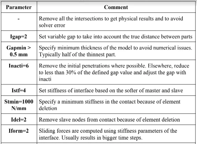
One of the drawbacks of type 7 contact is that it cannot remove the element intersection that is present in the model. To avoid that kind of issue and edge related intersection, type 11 contact is preferred. Type 11 works very much similar to that of type 7 but the search is for only the edge of the model.
Procedure
Part 1
Importing geometry
The first step is to open the HyperWork software and in the interface it will ask to select the a solver, here we select Optistruct as a solver. The we need to import the .hm file.
Than go to file ->import->select the component from directory and click import

Geometry clean up
The primary stage of meshing any part is to clean the geometry, if the part created in any modeling software and then imported in any CAE software due to change in the formate of the file. some error in the geometry can be seen like Free egdes, deformed shape, duplicate surface, missing surface, unconnected adjection surface so on and so forth
Meshing
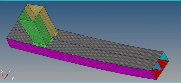
Go perform mesh on the model, got to 2D panel-> Automesh-> assign elements target length as 6 and other parameter-> select the surface to mesh-> click on mesh.
Part 2
Case 1: Run the crash model as it is.
Now, click on New model and change solver as Radioss. Then we need to import the Crush_tube_0000.rad file.
Than go to file ->import->select the component from directory and click import
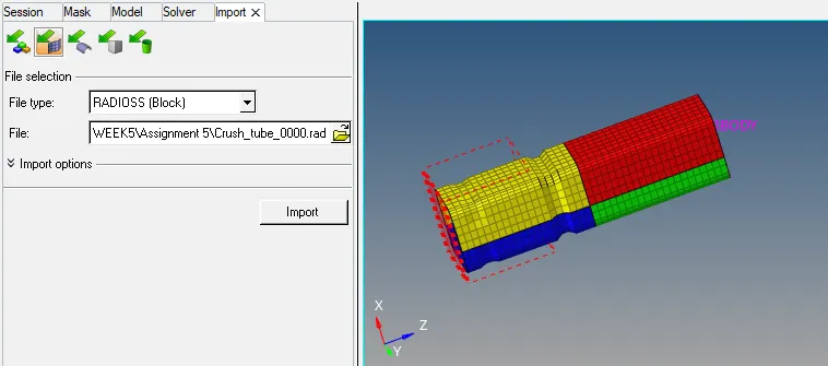
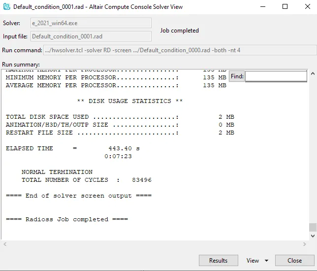
To run the simulation, Go to Analysis->Radioss. Save the file as "Default_condition.0000.rad". In option type -nt 4 which means assigning the task to 4 cores in the system, to perform the simulation faster.its depends upon the process of iur computer(it has a quad- core processor, than it will take as 4. if the system has an octa- core processor than it is taken as 8). nt means number of threads, finally click on Radioss in order to run the simulation.

After clicking on Radioss we get the solver window as shown below, after few minutes Radioss does the job and click on Result
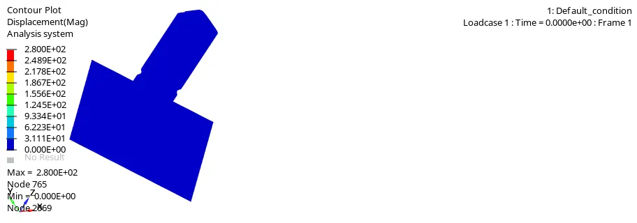
After Clicking on result it will switch to Hyperview window. Now on Hyperview we should input the the simulation file for this we use .h3d file that was generated when Radioss Processed the starter file(Default_condition.h3d) after selecting it click on apply. Now to simulate the animation click on contour option in the toolbar. Animation will start as shown below
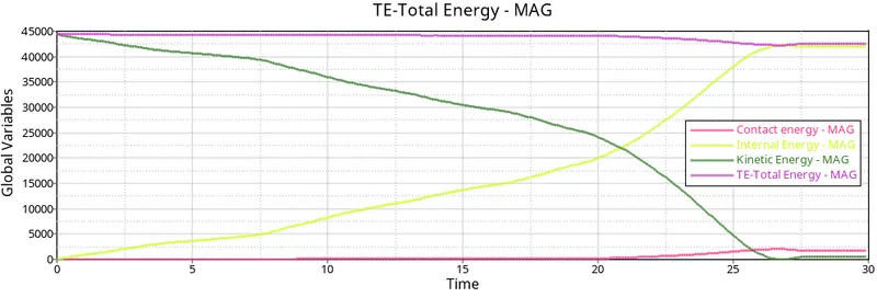
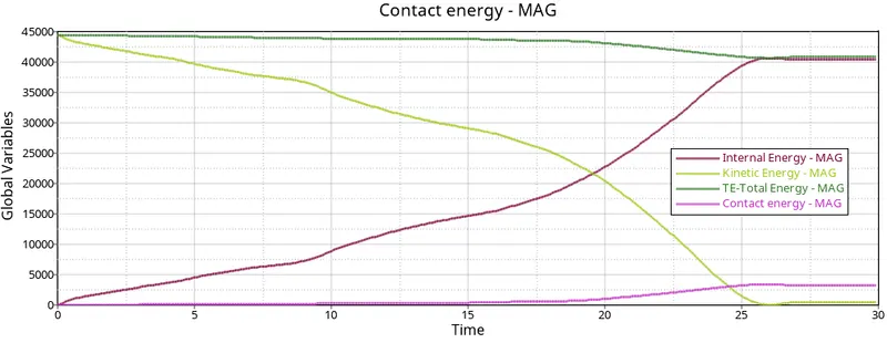
Internal Energy keeps increasing because the tube continuosly absorbs energy while crashing onto the rigid wall, which results in deformation. we can see that at last when the deformation completes, the internal energy goes constant.
Kinetic energy keeps decreasing due to initial velocity on the tube. the curve starts from high value and decreasing to low to the deformation. there is a slight increases afterward due to rebound after deformation.
Total energy is the sum of kinetic and potential energy, is decreasing at some point due to increasing of contact energy at the same time, so, contact energy affects the total energy
Contact energy is a type of energy that is created when one element contacts neighboring elements. the opposing force created by elements is called contact energy. there are no contact energy at the beginning, after 20 ms contact energy is increasing due to buckling of the elements as shown in graph
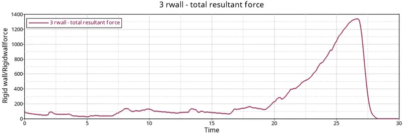
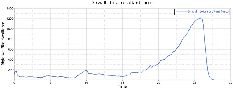
It is evident that the wall experiencess some forces suddenly, due to the crush tube over the rigid wall and absorb the energy from crush tube after the deformation completes, the rigid wall force is decreasing immedoately due to the energy transfer completely.
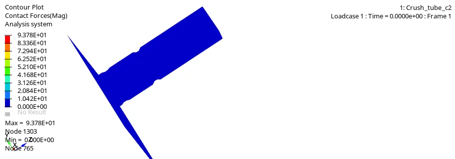
Self contact force
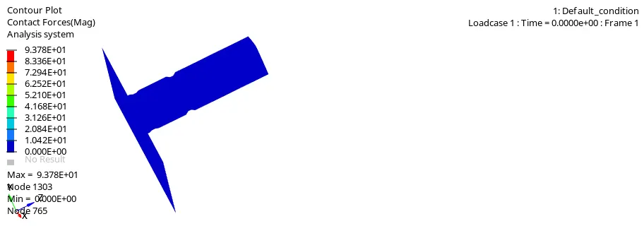
From the animation we can the maximum self contact force is 93.78 kN. which occurs at the simulation, this is the point where a maximum number of master and slave segments are in contact with each other.
Case 2 Change the inacti = 6 and run
In this case, we will be using HyperCrash. now we need to import the starter file in HyperCrash, go to file->import or we can directly drag and drop .rad file
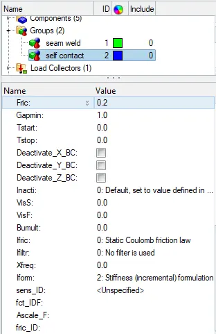
After importing go to model browser tab, contact interface->self-contact and then right click on it. change inacti to 6.
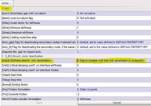
After that, we need to export the model from HyperCrash with an appropriate file name. now this file is open in HyperMesh and run the analysis.
There isn't any noticeable difference between cas1 and case2, they are much very similar in term of energy error and contact force.
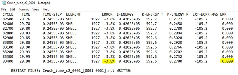
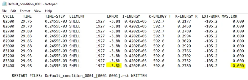
As we can see, the value are the same as in case1, the energy error is -3.8% and mass error 0% which is same as case1.
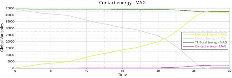
There isn't much different in the graphs. they exact are same as case1. The only thing we have learned from the energy plot/graph is no initial penetration since there are no difference case1 and case2.
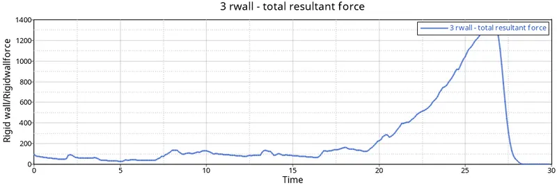
Rigid wall force also exhibit the same characteristics as case1.
Case 3: Create the type 11 contact and run
In this case, we need to add type 11 interface to case 2 solver deck file. After importing it in hyperCrash
for both slave and master select all the components of the model. input the recommended parameter in type 11, than export with suitable file name.
As usual, the file can be processed using the radioss slover.
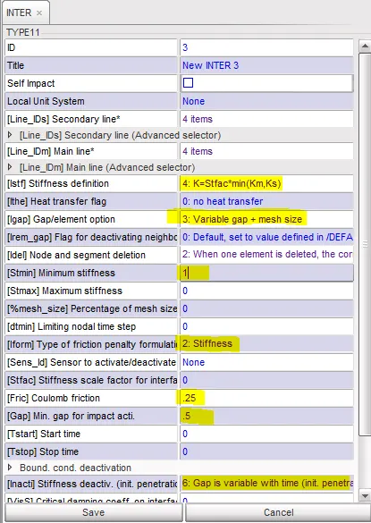
Import the created file in HyperMesh and run the simulation as usual
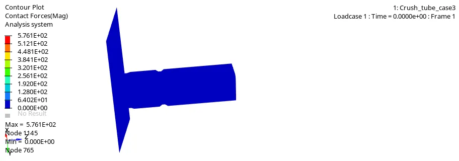
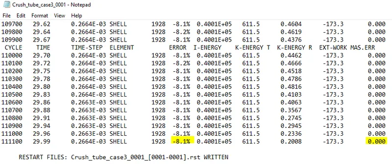
The energy error is still within, energy error as -8.1% and mass error is non-existent.
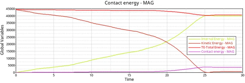
The internal energy which is representative of the energy absorbed, increases with time, as the tube contacts the rigid wall. we can observe a small peak and a drop off at around 25 s, which is the time when the tube is completely crushed and no more energy can be absorbed.

There are no discernible difference between the energy and the rigid wall plots of this case and previous cases.hence, we can conclude that there was no edge to edge penetration in this model.
Case4: Remove both notches and remove boundary condition on the body node than run
Import the case2 0000.rad file. then remove the notch in the model using align option under node edit.
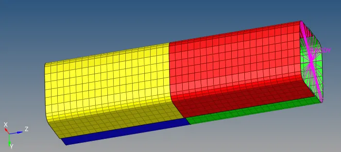
Also delete BC's as shown below.
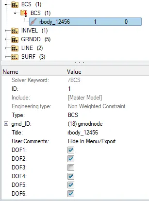
After deleting BCS and notch and run the analysis as usual
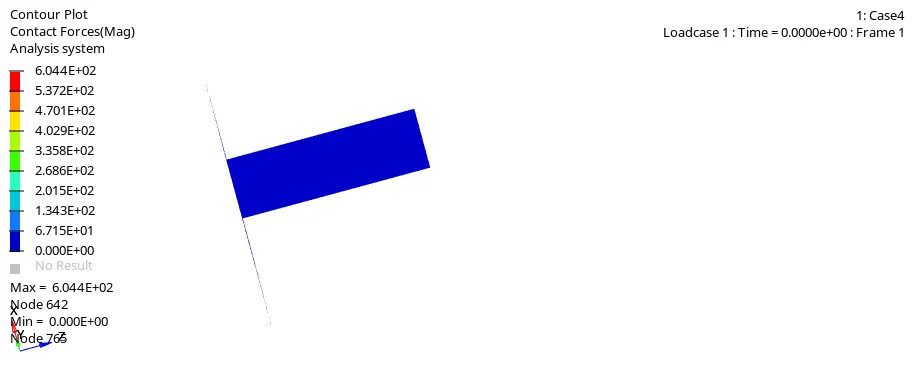
There is no notch present in the model, the buckling started at the contact takes place in rigid wall and tube,in previous cases buckling started at notch areas.
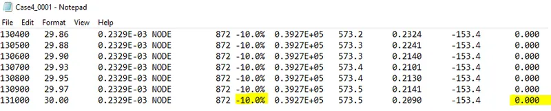
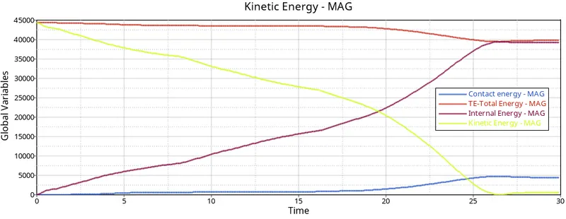
Internal energy increasing at some point due to buckling of the tube. The more energy absorbed by tube when deformation takes place.
Kinetic energy decreases from maximum due to internal energy increases.
compared to previous cases, contact energy slightly decreases after some point due to absence of notches.
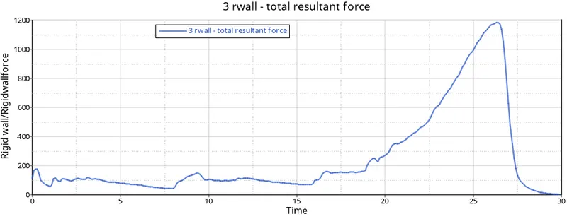
In this case, the Rigid wall force graph peak some point due to large amount of force transferred to the rigid wall during the collision of the crush tube, after the deformation was completed, the graph decreses suddenly and got constant value of deformation.The resultant force peak at around 1190 N(shows decrease in value).
Case 5: Create a new notch in the middle, select the whole section and run
Import the starter file of case 4, since there are no notches, But the case require us to create a notch through the middle of the crush tube, used translate tool in Hypermesh to create notch by selecting nodes.
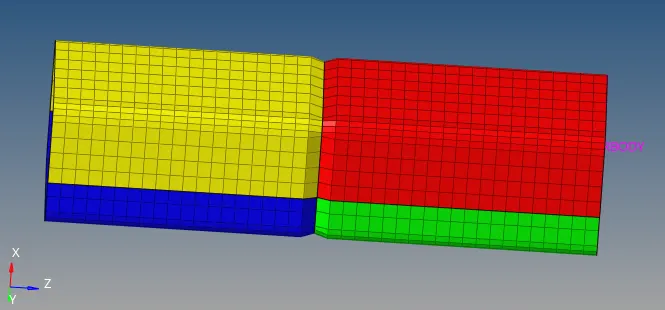
fig:- Notch created on the middle
Run the simulation as usual
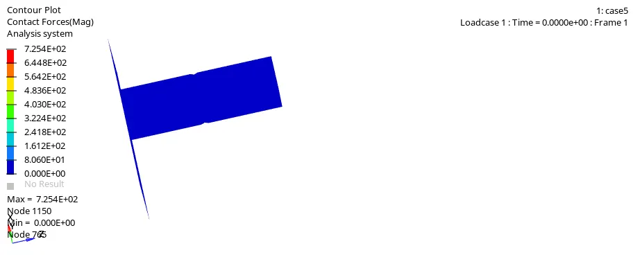
From the first 3 cases, the notch is the region where the tube undergoes deformation first,than the region closer to the rigid wall is deformed next. when the lower half is mostly deformed, the upper half undergoes proper, visible deformation very rapidly until the entire tube is crushed completely.

Energy error is still within the limit, energy error -10.2% and mass error is 0%.
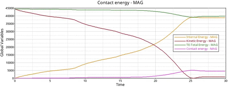
As usual,internal energy keeps increasing due to the deformationthat take place. kinetic energy decreases due to increase in internal energy, while contact energy slightly changed in early cases.
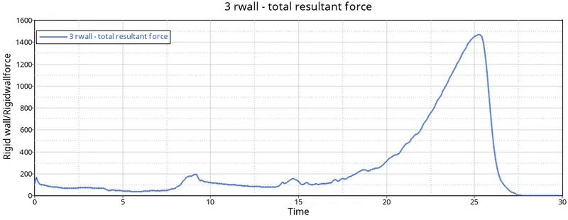
We can notice that Rwall force in this cases is slightly increses compare to case4 which is due to present of notches.
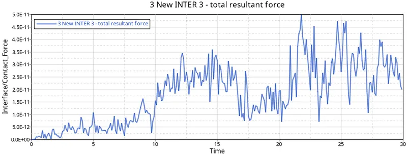
Case 6: Create new notch with nodes only from opposite 2 faces and run.
Import the starter file of case 4, since there are no notches, But the case require us to create a notch through the opposite face of the crush tube, used translate tool in Hypermesh to create notch by selecting nodes.
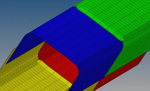
fig:- opposite notch on face
Run the simulation as usual
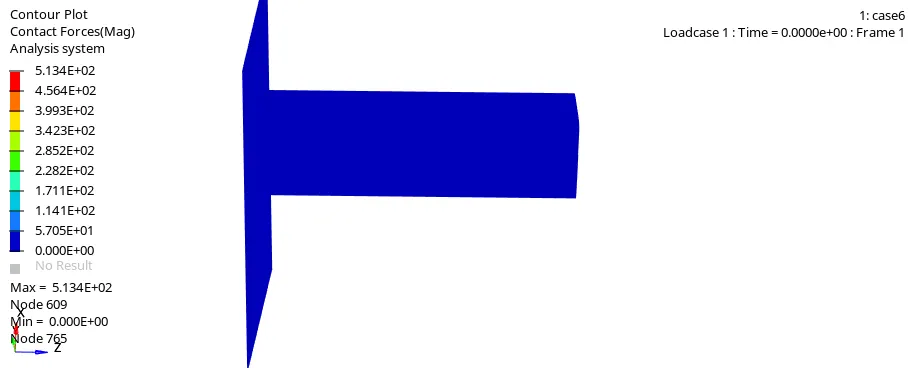
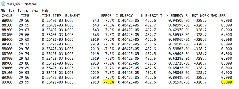
As usual open 00001.out file to check energy error and mass error. in this cases energy error is -7.3% which is in the limit.
Like in previous cases, the internal energy increses dure to the deformation occur. kinetic energy decreses from high value due to increases in internal energy.
Comparision
| Contact force(KN) | Rigid wall force(KN) | Internal energy | Energy Error(%) | |
| Case1 (Run the crash model as it is) | 93.78 | 1320 | 42020 | -3.8 |
| case2(Change the inacti = 6 and run ) |
93.78 | 1320 | 42020 | -3.8 |
| case3(Create the type 11 contact and run ) |
576.1 | 1500 | 40010 | -8.1 |
| case4(Remove both notches and remove boundary condition on the body node than run ) |
600.4 | 1190 | 39270 | -10 |
| case5(Create a new notch in the middle, select the whole section and run ) |
725.4 | 1485 | 38880 | -10.2 |
| case6(Create new notch with nodes only fron opposite 2 faces and run. ) |
513.4 | 1220 | 40420 | -7.3 |
- In all the cases hourglass energy seem to be same because in none of the case properties is change (recommended properties is assigned)
- Mass error in all the cases is 0%
- Internal energy in all the cases are sen to increasing expontially to maximum value and then decreases.
Learning outcomes
Learned to simulate the different scenario problem
Learned different command and tools in HyperCrash and types of interfaces and its application
Conclusion
Different cases is simulated Using HyperCrash and Radioss. From all the cases we can say that, inacti is required to be defined as it removes any initial intersection in the model if they exist, helps to obtain more accurate result and reduce the number of cycles & time to solve. Notch are important part of the model which help in detecting deformation when a load is applied, they help in making the component absorb maximum energy when a load is applied.