Assignment 5-RADIOSS Interfaces & Study of Effect of Notches Challenge
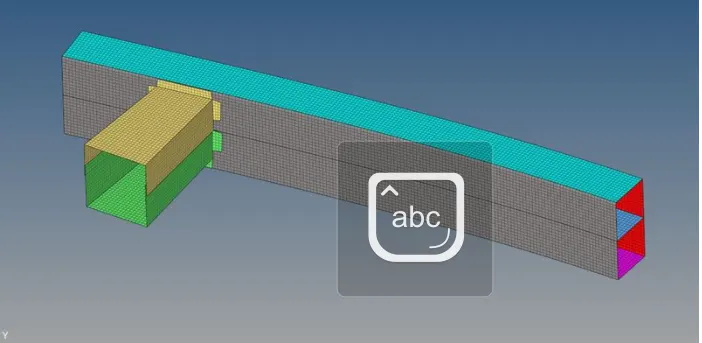
Objective :Create the mesh for bumper assembly,mesh size should be 6mm.
- Run the crash tube model as it is.
- Change the Inacti=6 and run.
- Create the type 11 contact and run.
- Remove both notches and remove boundary condition on rigid body node then run.
- Create a new notch in the middle ,select the whole section and run.
- Create a new notch with nodes only from opposing 2 faces and run.
Create the mesh for bumper assembly,mesh size should be 6mm.
The model was downloaded as an Hm file so it can be directly opened without importing
The model was having free edges on the surfaces hecne needed to clear those edges by qick edit pannel
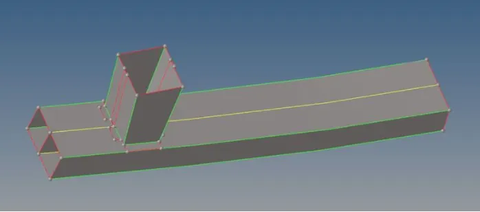
After this clean up the model was meshed through the 2D Automesh Tab and finally the model was meshed with given above target elem size 6mm
- Run the crash tube model as it is.
The Crash tube model was imported in the Hypermesh window through the import option in HM and after impotrting below model was fitted into window
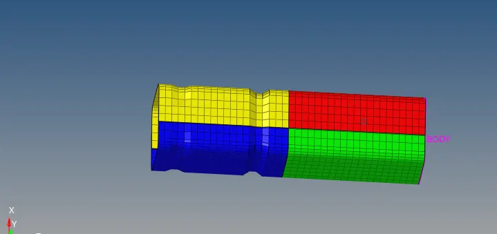
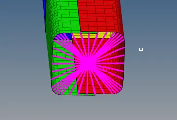
The model is having Rigid connection at the end and few notches on the surfaces
The case 1 tells us to run the model as it is without making any changes to the model, for running the simulation the analysis tab is used
Interfaces solve the contact and impact conditions between two parts of a model. Several interface types are available in Radioss and use different contact treatments.
Case 1: The model has to be run without any modification to properties,hence the default values are to be used for simulation
In the first case the type 7 card is used which is node to surface contact method
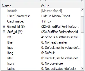
After this simulation was carried out on the file Crash beam
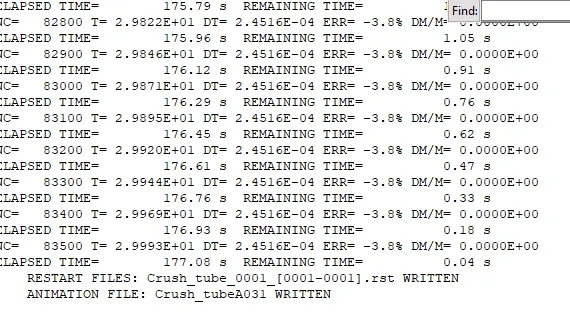
The simulation was carried out on the file and the above results were acheived , the energy error is -3.8% which is acceptable
The simulation file was ran through the hyperview window to undersatnd the simulation through animated view
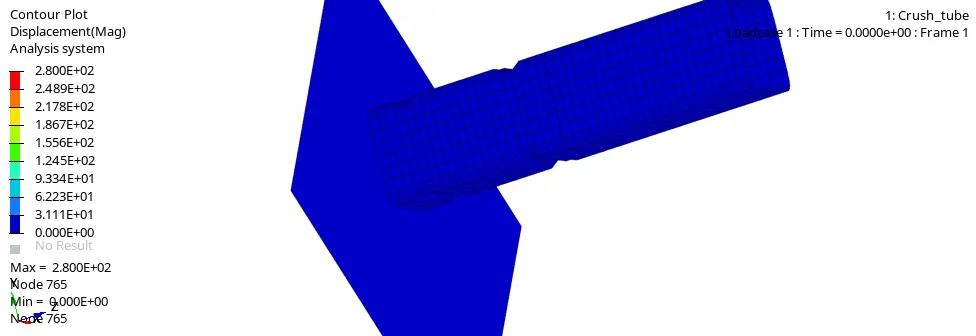
The max stresses are observed at the elements which are at the end of surface and max stress is 2.8E^2 KN
Further the RWALL forces ,contact forces,internal energy's were plotted using the hypergraph 2D 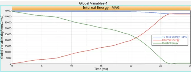
From the above graph we can undertsand that the internal enery starts increasing eventually with respect to time and kinetic energy decrease decrease with respect to time
The decresase in kinetic energy tells us that the crash tube has started deforming as we apply force on the can and simultaneously the internal energy incresases
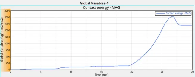
The contact energy plot above tells us that the conatct energy incresase gradually and at the end graph remains constant .the increase in contact energy is due to friction formulation
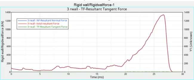
The Total resultant tangential forces increase at 20 ms and gradually decrease as the tube starts to deform after 25 ms
Case 2: Change Inacti=6 and run the simulation
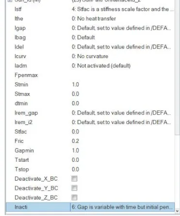
From the Solver tree the interfaces tab was selected and inacti=6 was modified and Inacti 6 says that Gap is varriable with time but initial penetration is computed
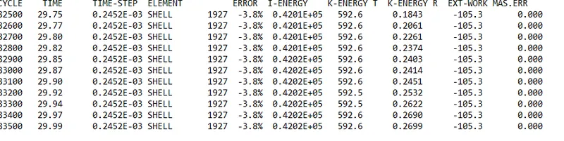
The energy errors began from zero and ended at -3.8% hence they are acceptable
Then after making neccessary changes the simulation was performed and the max stress was 2.8E^2 and the stresses in previous cases are same as compared to this case
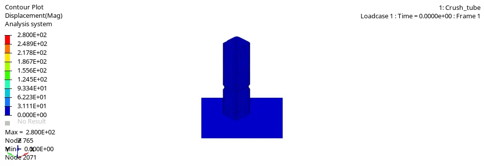
And after this time history plots were plotted using hypergraph 2D using TO1 file
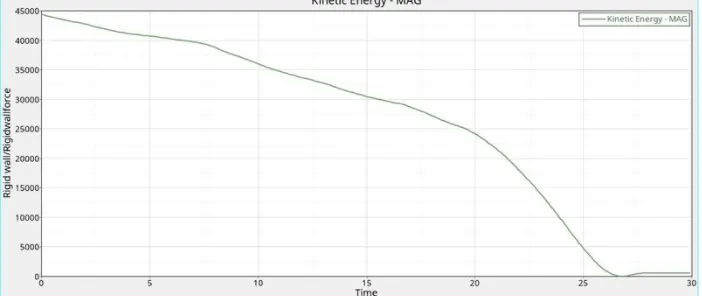
The kinetic energy plot above shows that kinetic energy increases with respect to time and gradually decrease as the tube begans to deform
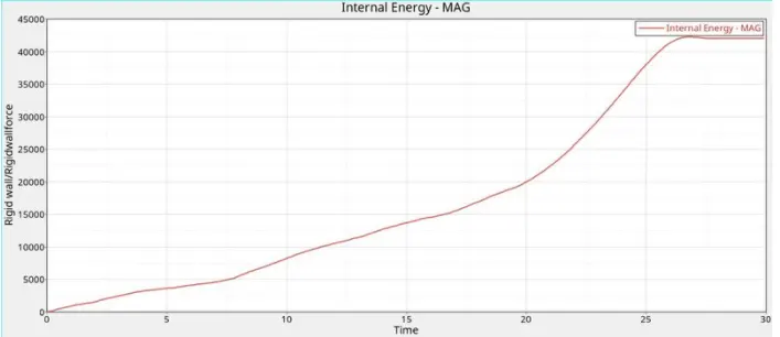
Intenal energy plot says that internal increase with respect to time and greater than the previous case and stops at 45000 .
This increase gradual increase in internal energy is due to Inacti 6 parameter
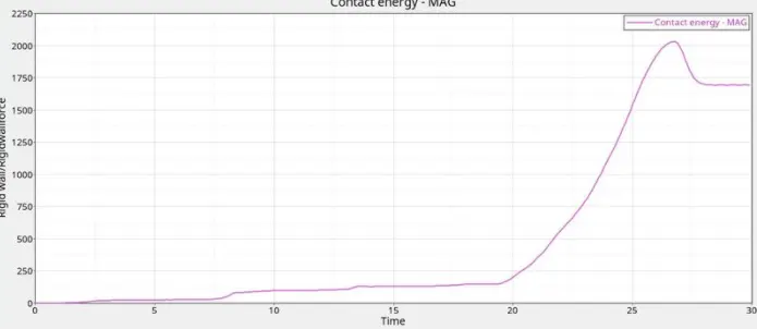
The contact energy plot above hepls us understand the contact forces whcih increase after 20 ms and remain constant during the max deformation of crash tube
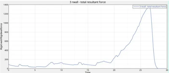
The total resultant forces plot briefs that resultant force start from 150 and gradully increases upto 1400 and slows down at the end of simulation
Case3: Create the type 11 contact and run.
In this case the TYPE7 contact was changed to TYPE 11 and simulation was run
The Inacti,Istf and several other parameters were kept default and simulation was run and the clean pictorial view below helps us understand the stresses
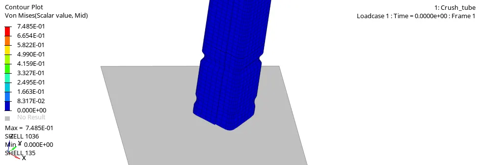
In this case the max stress deveoped in 0.78 mpa starting from 0 mpa
The deformation starts at notch first and then its concentrated at the edge of component,because at the notch there is less resistance strength on that area
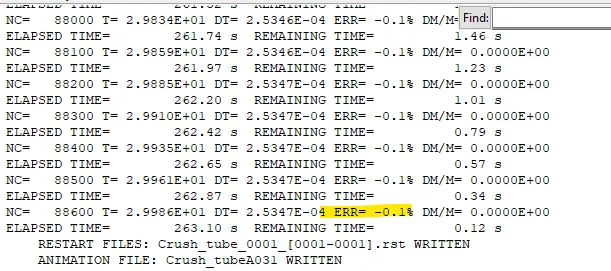
And the energy error at end is -0.1 which is acceptable
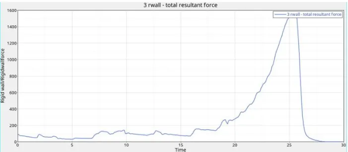
The resultant forces increase from 150 to 1600 N and decrease at end of the simullation,the resultant force has "increased by 200 N" than the previous case.
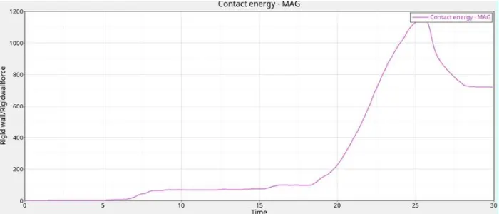
The contact energy increase from 5 ms and reamins conctant till 15s and increases till 1200 N and decrease gradually after 27 ms
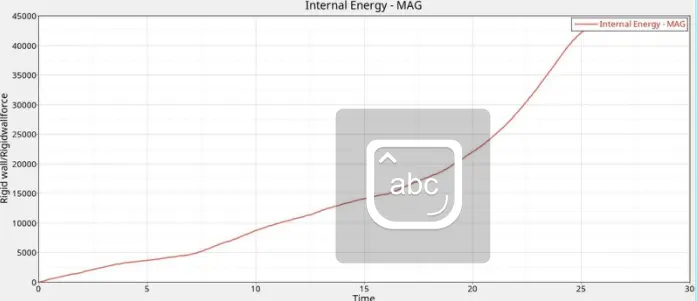
Internal energy plot shows that internal energy increases from zero till 45000 which is greater than previous cases
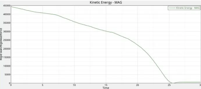
The kinetic energy increase from 45000 and decreases at 25 ms to 0 and remains constant till time
Case 4:Remove both notches and remove boundary condition on rigid body node then run.
In this case the notches were removed from the model,this was done using nodes edit tab in Hypermesh
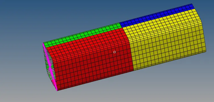
The model will look like above after removing notches,and lets check further for any changes in simulation after removing notches
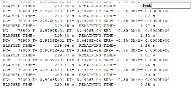
The energy errors found to be -0.3% at the end of simulation which are acceptable
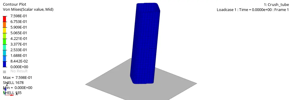
From the above simulation we come to know that elements has started to deform from the bottom as the notches has been removed.
and Max stress acheived is 0.7 Mpa
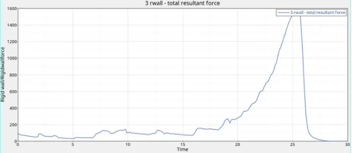
The rigid wall forces are same as the previous case.there is no change observed
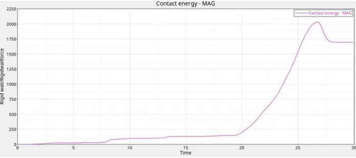
The contact energy plot also remains the same as previous case after removing notches
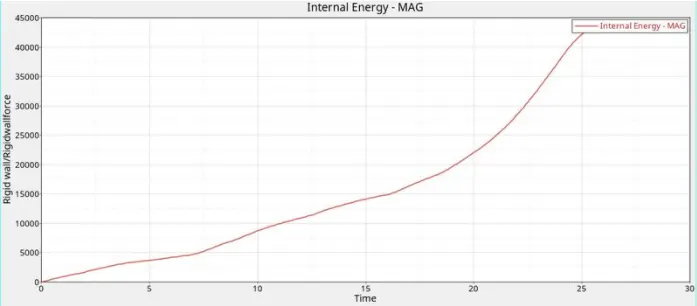
The internal energy remains the same as previous case
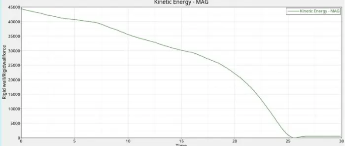
The kinetic is also same as the previous case after remocing notches on the model
Case 5:Create a new notch in the middle ,select the whole section and run.
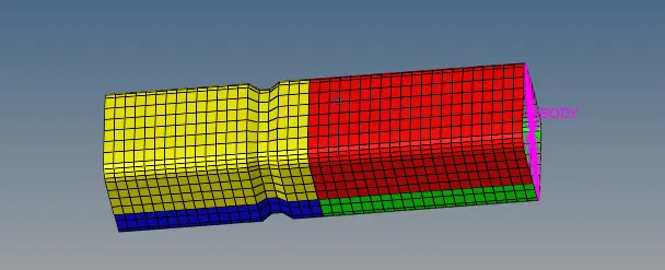
The middle notch was kept as it is and the notches at the end were removed and the model was looking like above image as shown in the fig
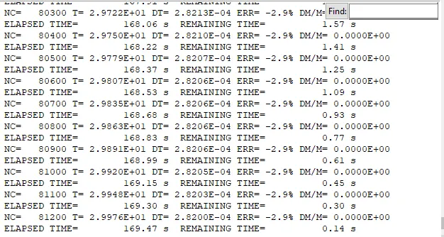
The energy errors were acceptable and were gretater than previous case
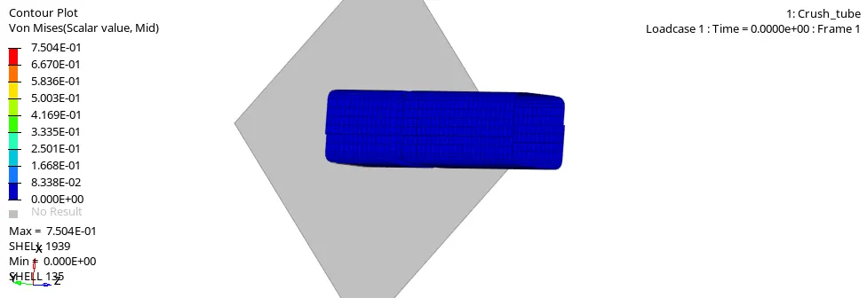
In this case the max stress is 0.7 mpa and deformation starts at the Notch region because there is less resistance strength on that area
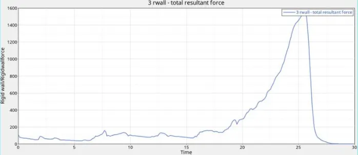
The Rigid wall forces are the similar as the previous case and there is no change after introducing the notch
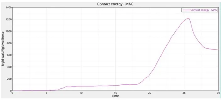
No changes observed similar to previous case
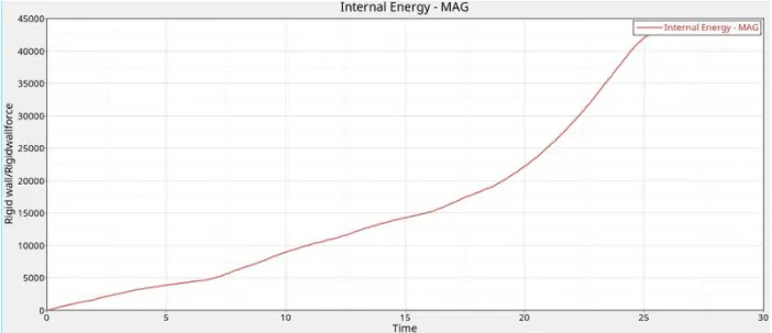
No changes in the internal energy
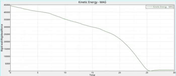
No changes in Kinetic energy
Case 6 : Create a new notch with nodes only from opposing 2 faces and run.
In this case notches were created at the two faces and this was done through translate option in HM
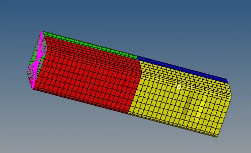
The Notches were created at 2 opposing and sim was run
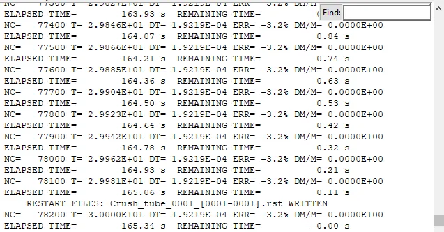
The energy errors are acceptable and within range(-3.2%)
In the above simulation we can observe that deformation has started at the notches and then and the to bottom area,becasue at the nocth region there is less resistance to stress
And max stress acheived is 0.75Mpa
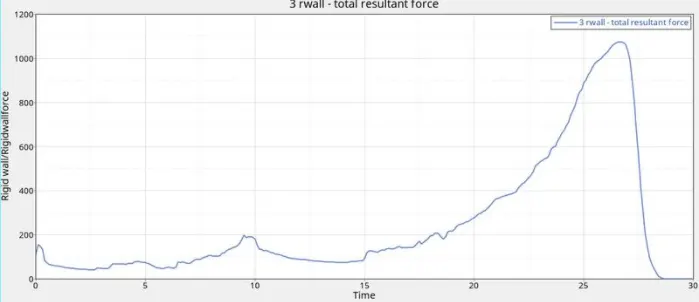
In this case rigid wall forces are varrying with respect to time 150 at 0 ms and reahces at 1100 N at 27 ms and gradually reaches zero at the end of simulation.
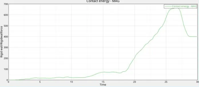
The contact energy has decreased than the previous case it starts from zero and reaches till 700 N
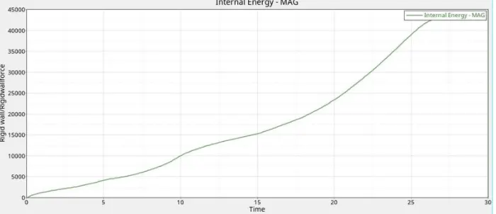
The internal energy has not varried as compared to previous case
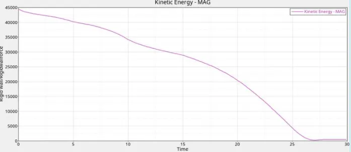
No cahnges observed as compared to previous case
Why there is change in internal energy ?
In the case 1 we have used TYPE 7 interface with default values and rest other cases the internal energy is less as compared to case because of Interface used is TYPE 11 for the rest cases
How does notch affect results ?
The notch is nothing but the change in C/S area of component which may lead to uneven stress generation
The case 4 has very less stress generation as compared to other cases
Conclusion: After completing simulation on the 6 cases we have observed that changing the Interface type and creating notches on the model results in varriation of the stress and aslo result in change to Rigid wall forces and contact forces with no change in Internal and kinetic energy
Learning Outcomes: Learned about the types of interfaces and their parameters and Also meshing the bumper with mesh size 6 mm