Assignment 5-RADIOSS Interfaces & Study of Effect of Notches Challenge
OBJECTIVE: (1) To mesh the bumper with mesh size 6mm and spot weld at the mentioned places.
(2) To Run the simulation of the crash tube using the given conditions and compare the results.
PROCEDURE: (BUMPER MESHING)
- Import the bumper file into the Hypermesh using the import model and check for any solids present in the model.
- Then switch to BY TOPO and check for any free edges present, if there are any free edges resolve them.
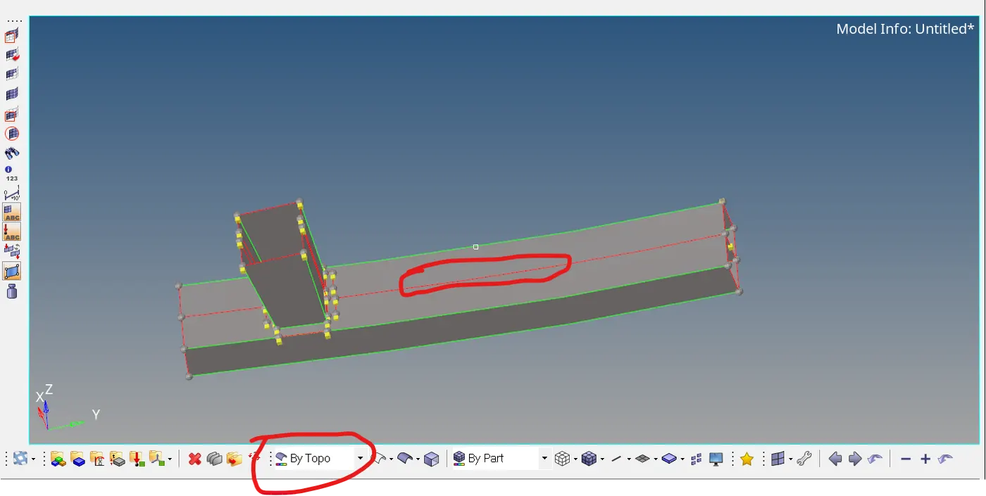
- After resolving the free edges meshing need to be done using the 2D->automesh->meshsize as 6mm. adjust the number of elements so that there are no or less number of trias.
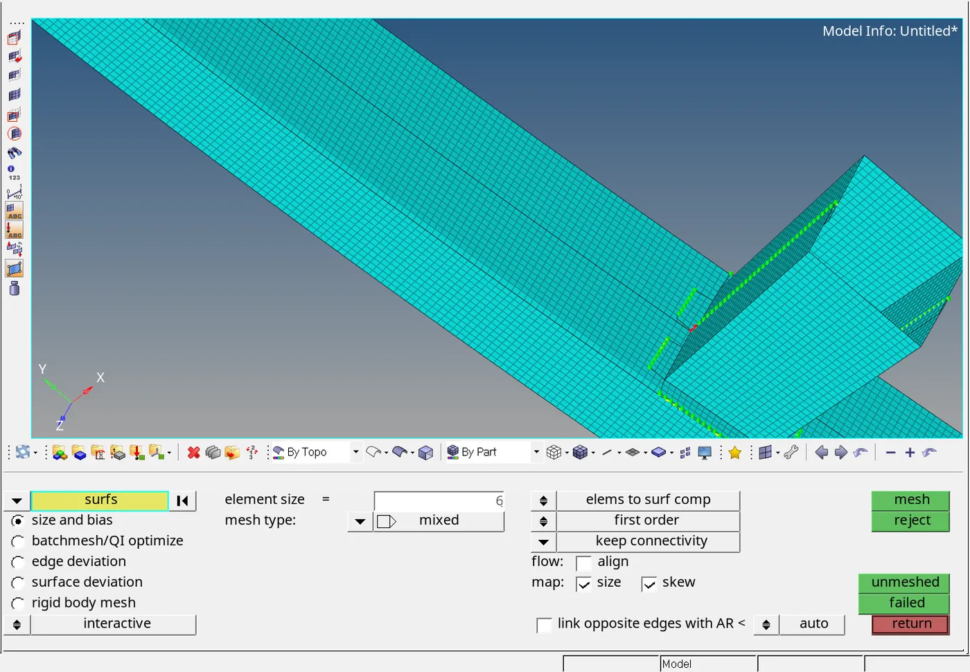
- After meshing spot welding need to be done which is in 1D->Connectors->Spot, the module is shown in the figure.
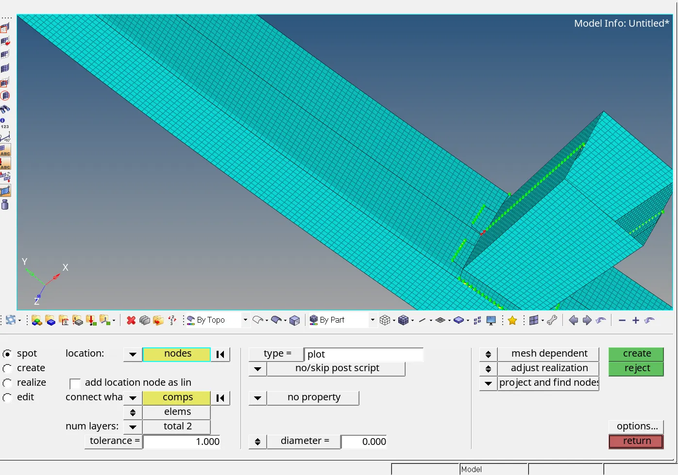
- The spot weld is done for the crash box and bumper, with search tolerance= 2.5, number of layers =2 and diameter = 2mm which is shown in above figure.
- Now the meshing and the spot welding is done for the given bumper.
PROCEDURE: (CRASH BOX SIMULATION):
CASE1:
- Import the given Crush_tube_0000.rad file into the Hyper mesh software using the import solver deck option available.
- Then run the simulation as per the given parameters.
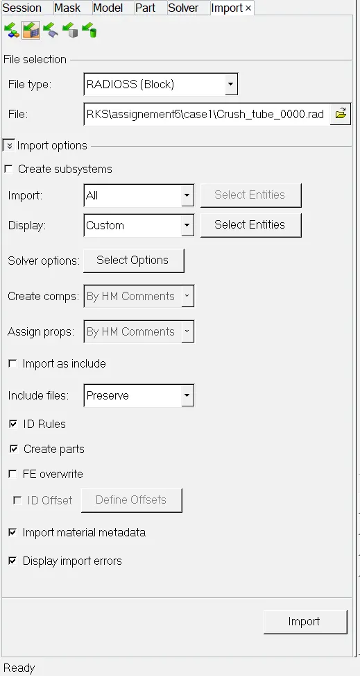
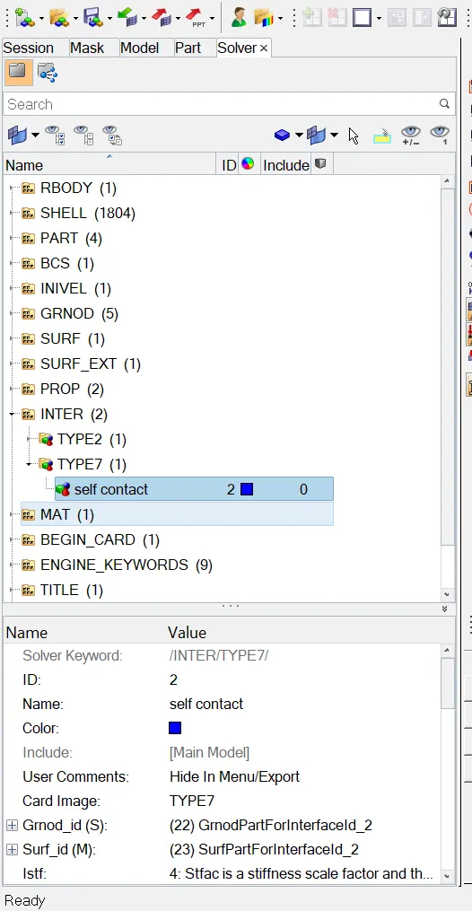
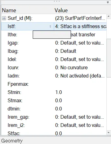
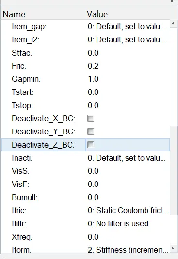
- With the above parameters we need to run the simulations as number of processors as 4 in the Analysis->Radioss module.
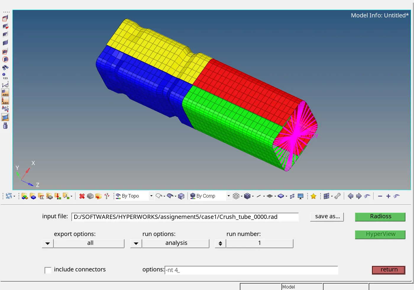
- After running the simulation the results are viewed in the hyperview using the h3d file. The animations can be seen in this file.
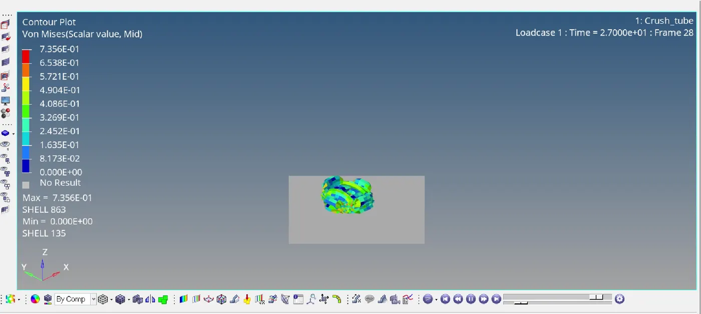
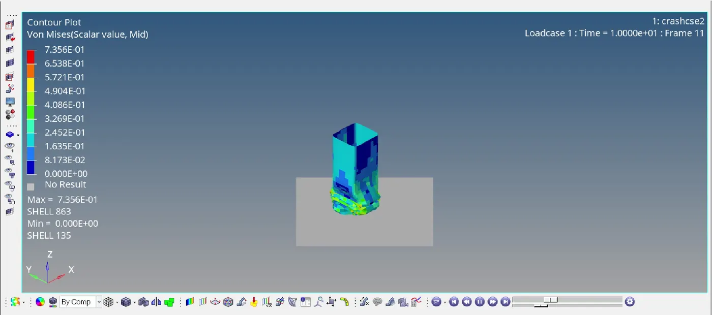
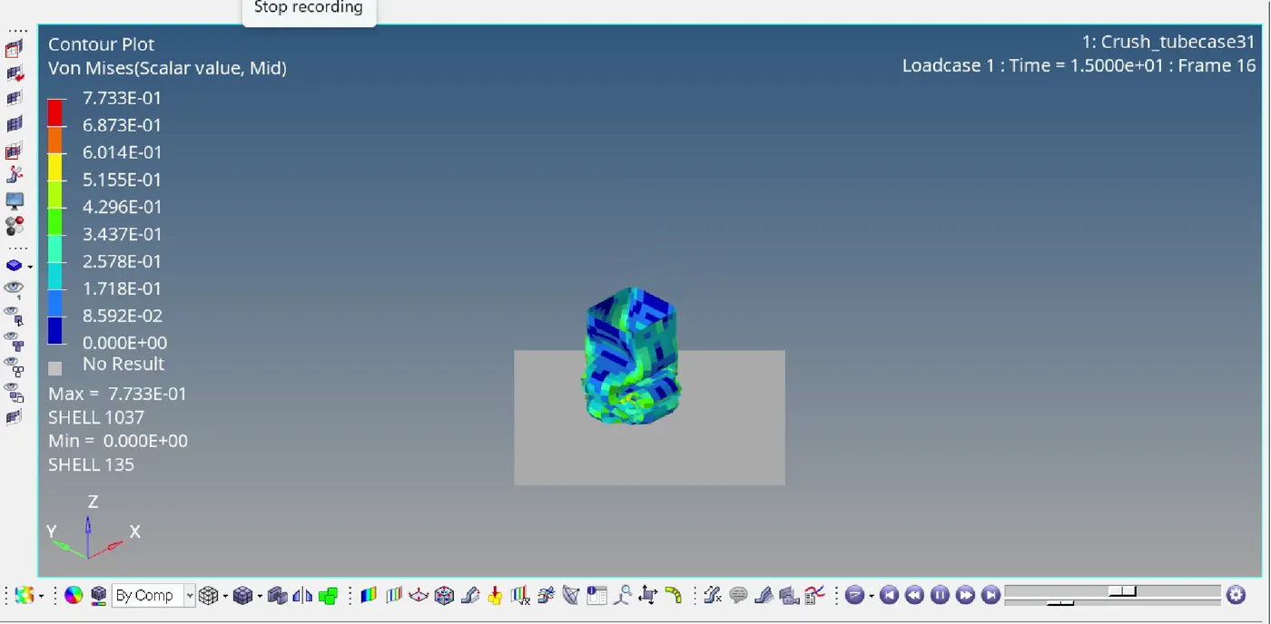
- The stress contour is shown in the following image. The max stress attained is 0.735Mpa.
- The maximum energy error is -3.8% which is acceptable range.
- In the animation given the crash tube will start to bend from the notch which is existed on the tube.
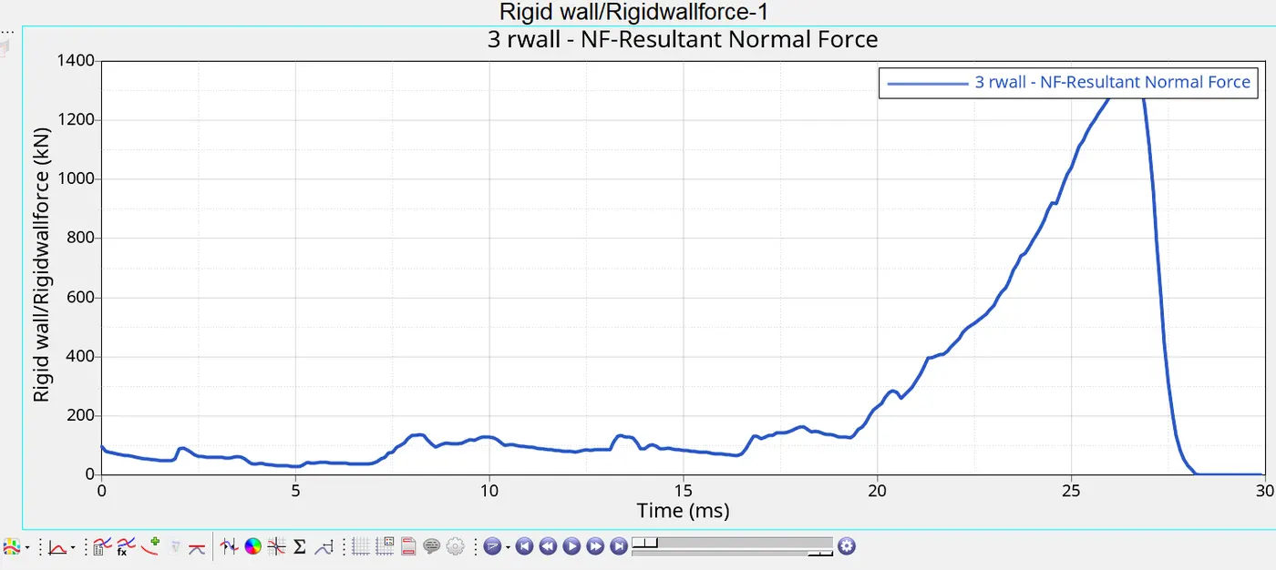
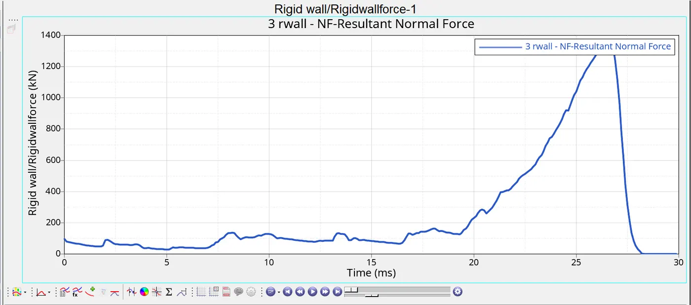
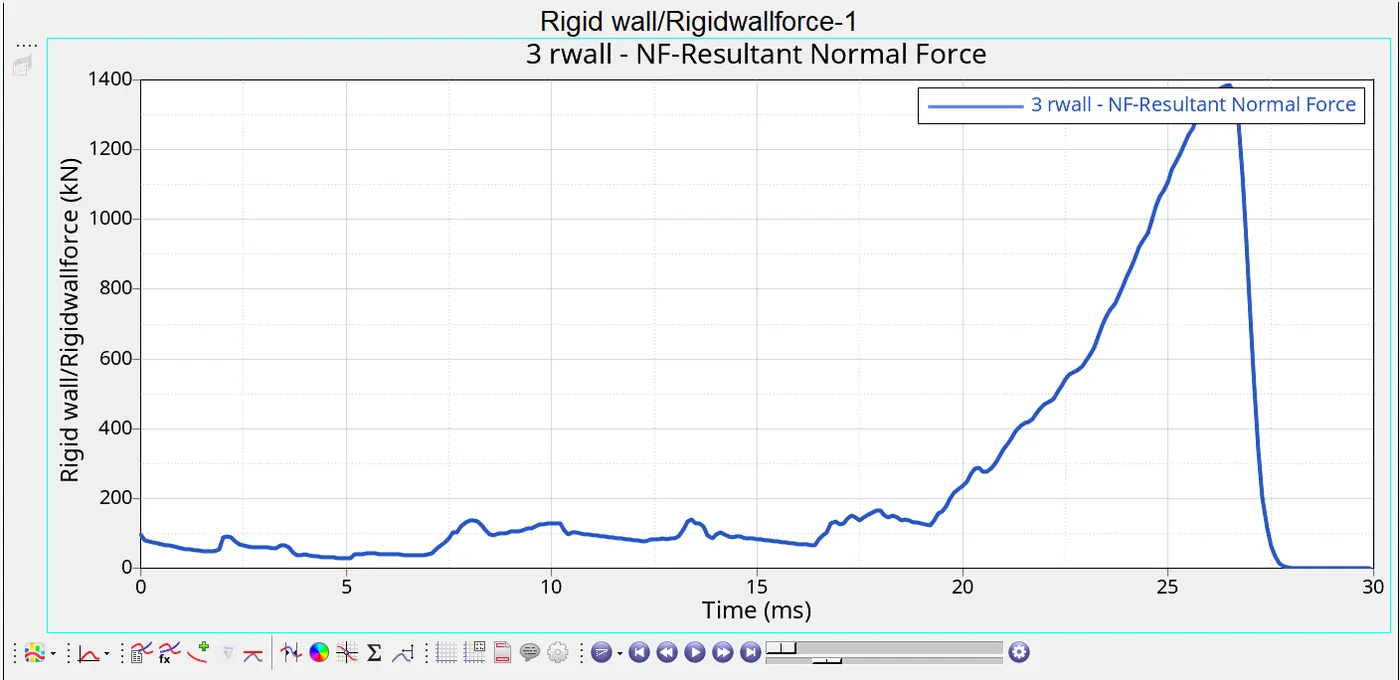
- The Rigid wall force is plotted against the time, as you can see from the graph that at T = 26ms the it reaches its peak because the crash tube is completely crushed against the wall and due to imposed velocity on the tube the forces are completely on the wall.
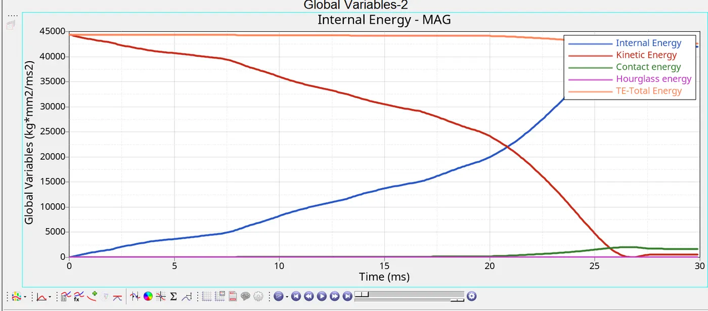
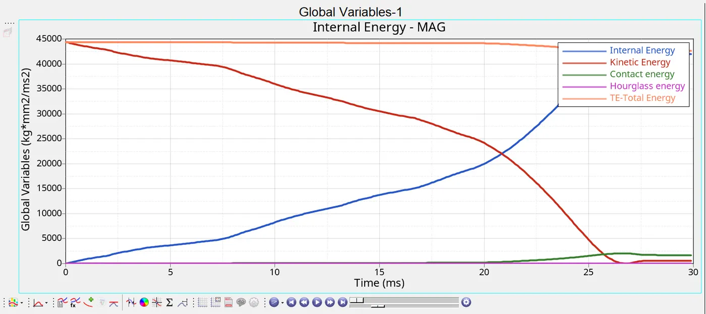
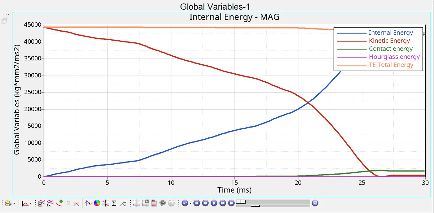
- The energies are also plotted against the time which is shown in the following figure. As one can observe that the as the kinetic energy decreases the internal energy is increases because this velocity is converted to the strain energy which is internal energy. The total energy is almost constant but at T =26ms due to complete crushing of crash tube there is a slight increase in contact energy, so there is a decrease in total energy. But the hour glass energy is almost 0.
CASE2:
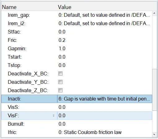
- In case 2 the only change is to use incti = 6 which will avoid any initial penetration present. This can be changed in the solver browser interfaces->TYPE7
- The remaining procedure is same the previous case, Run the simulation and extract the results.
- Here there is no much difference in the results because there is no initial penetration. The energy error is also in the acceptable range of -3.8%.
CASE3:
- In this case the type of contact need to be changed from TYPE7 to TYPE11. This is done using the HYPERCRASH specialized pre-processor for RADIOSS using units kg mm ms.
- TYPE11 uses EDGE to EDGE contact which can be changed in the LOADCASE->CONTACT INTERFACE.
- TYPE7 is node to surface contact and TYPE11 uses line to line and that is the only difference between them, the penalty method, gap definition and search method all are same.
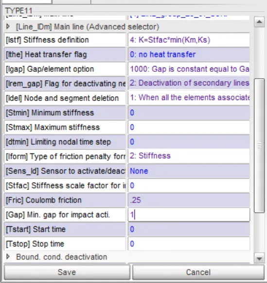
- After giving the type11 contact to the crash tube we can export it to HYPERMESH and run the simulation using the radioss profile.
- In this case also there is no much difference in the energies and rigid wall forces when compared to the previous cases .
CASE4:
- Here in this case the Notches need to be removed from the crash tube and run the simulation.
- The notched can be removed by using the GEOM->NODE EDIT->ALIGN NODE can be used to align the nodes in the notches to the crash tube nodes.
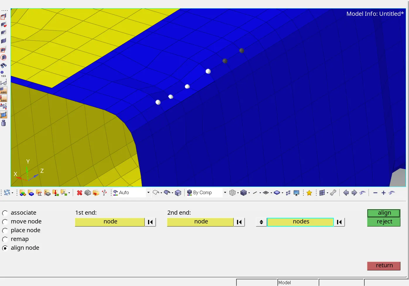
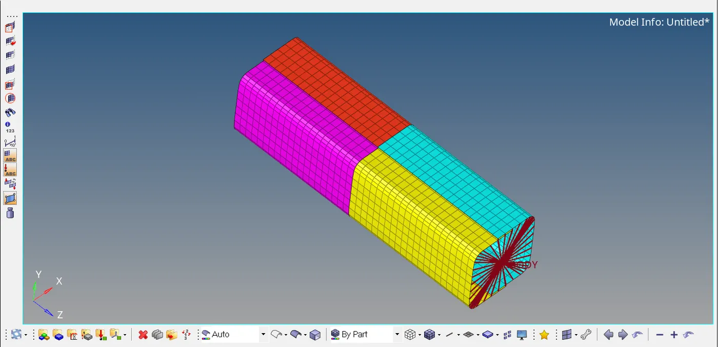
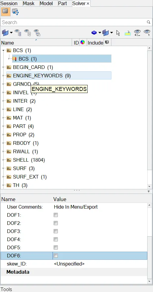
- After aligning all the nodes, the boundary conditions are removed then we need to run the simulation using the RADIOSS profile run the simulation and extract the results using the hyperview and hypergraph 2D.
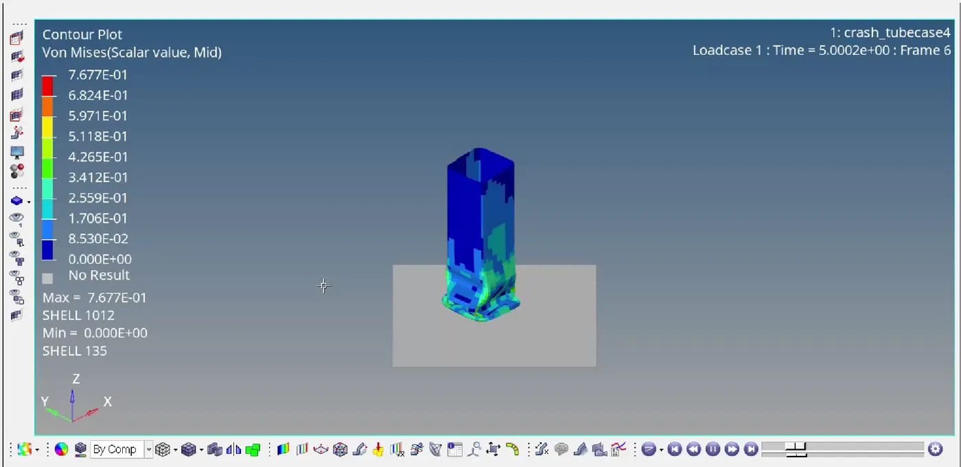
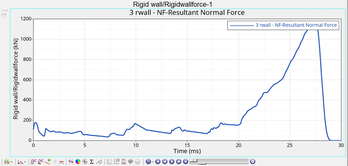
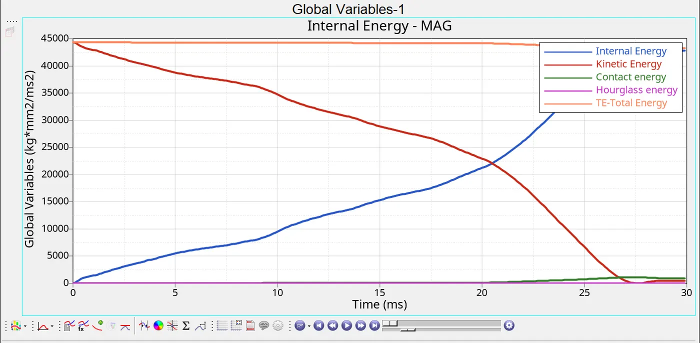
- The results obtained are similar to those of the previous cases, as their are no notches available on the crash tube then the deformation is as expected. The energy error is also within the acceptable range of -2.2%.
CASE5:
- In this case we need to create the notch using the TOOL-> TRANSLATE and select the nodes and the give the direction, create the plane using the N1,N2,N3 which should be perpendicular to the direction of nodal movement.
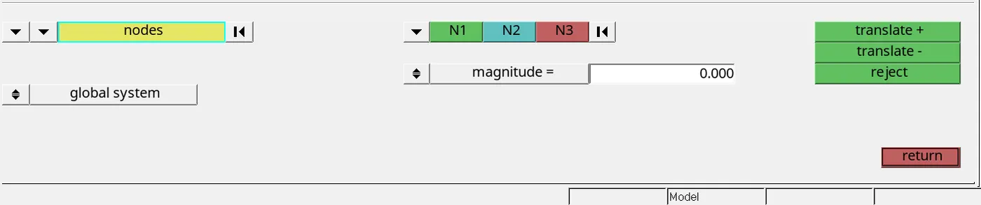
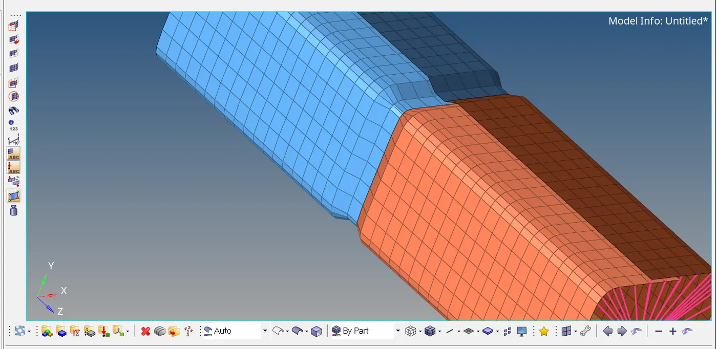
- The notch is created at the center of crash tube and perform the analysis and extract the results.
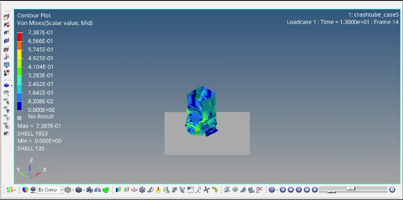
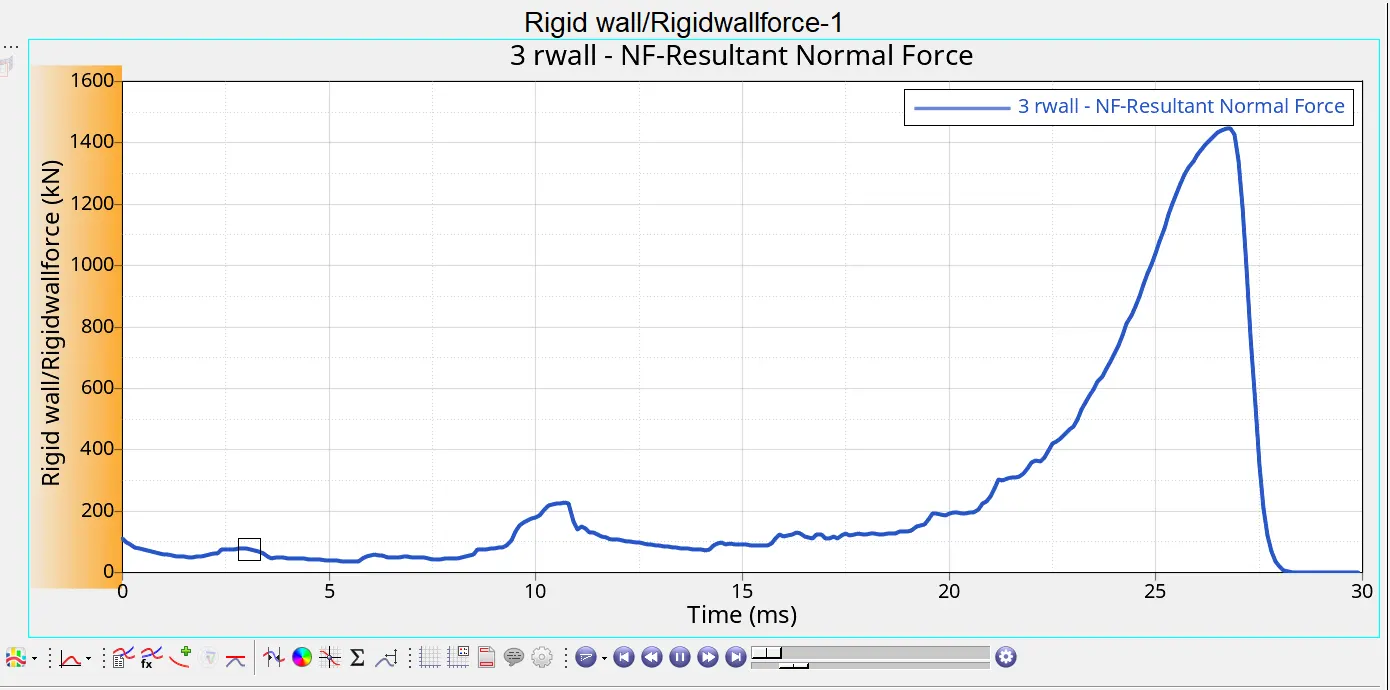
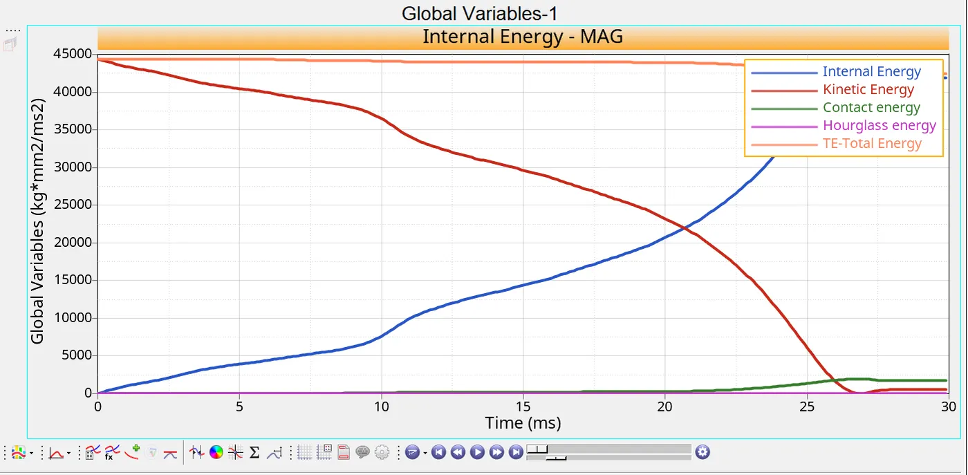
- The stress generated are almost same as that of the previous cases. The Rigid wall forces and the all the energies are also same. the energy error for this case is 3.9% which is acceptable value.
- Here in this case notch should be provided on the opposite faces of the crash tube and perform the analysis.
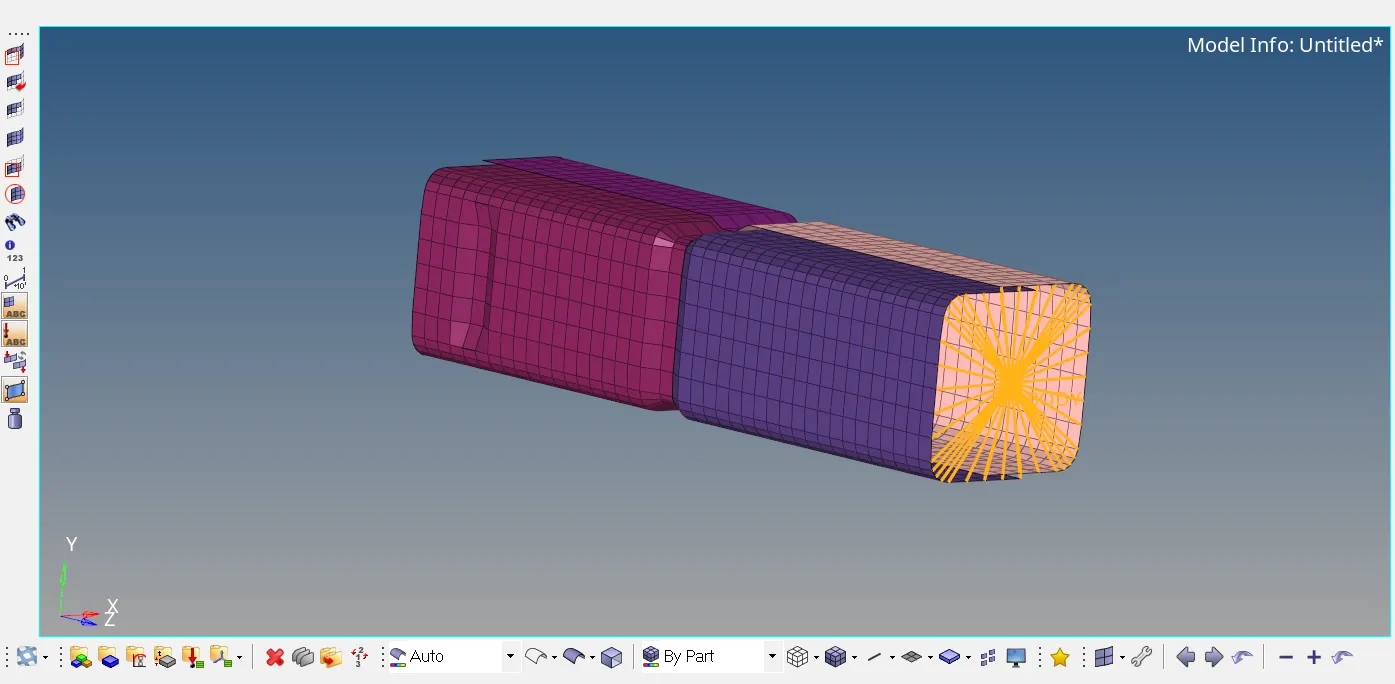
- After creating the notches on the opposite side of the crash tube we need to run the simulation and extract the results.
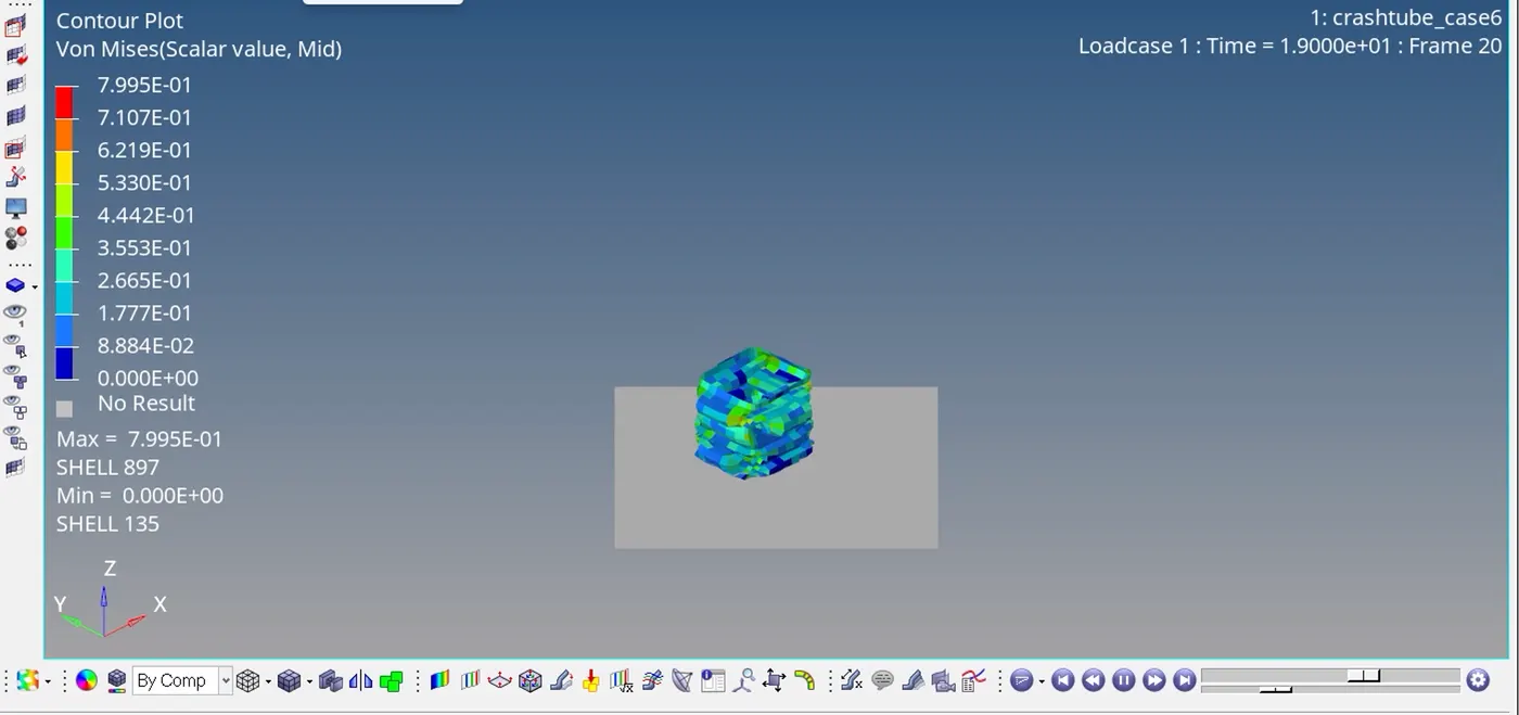
- The stress is 0.799Mpa which is almost nearer to the previous cases. The rigid wall force and all the energies are also similar to the previous cases. The energy error is -3.8% which is also in the acceptable range.
- The analysis is performed on the crash tube for the different cases and extracted the different energies and rigid-wall forces.
- It is observed that the energy error is least in case4 because of the no notches are present.
- Except for case 1 the initial penetration is considered in all the other cases, If there is any initial penetration is present which cannot be found in case1 can be found using other cases.
- Here in this assignment effect of notches and contact type are clearly understood.