Assignment 5-RADIOSS Interfaces & Study of Effect of Notches Challenge
The goal is to create a 6mm mesh for the bumper assembly, sihttps://drive.google.com/file/d/1eNTPhdPxyygggg4A_Njoe_3kfZ_JrpPN/view?usp=drive_linkmulate the model with seven distinct radio scenarios in accordance with the issue description, and compare the results using different graphs.
Questions: Create the mesh for bumper assembly,mesh size should be 6mm.
Run the crash tube model as it is.
Change the Inacti=6 and run.
Create the type 11 contact and run.
Remove both notches and remove boundary conditions on rigid body nodes then run.
Create a new notch in the middle ,select the whole section and run.
Create a new notch with nodes only from opposing 2 faces and run.
Note :
Plot RWALL forces, contact forces, internal energy and Create TH/PART for all parts and compare results for all cases.
Comment your thoughts on why there is a change in the internal energies.
How does the notch affect the results?
Plot energies and note any difference.
Model : Bumper assembly meshing
Bring the specified model into Hypermesh.
Navigate to the File option in the Standard menu bar >> to open the.hm file. Select Open. Select Model >>. To open the model, select it and click.
The model appears in the Graphics Area.
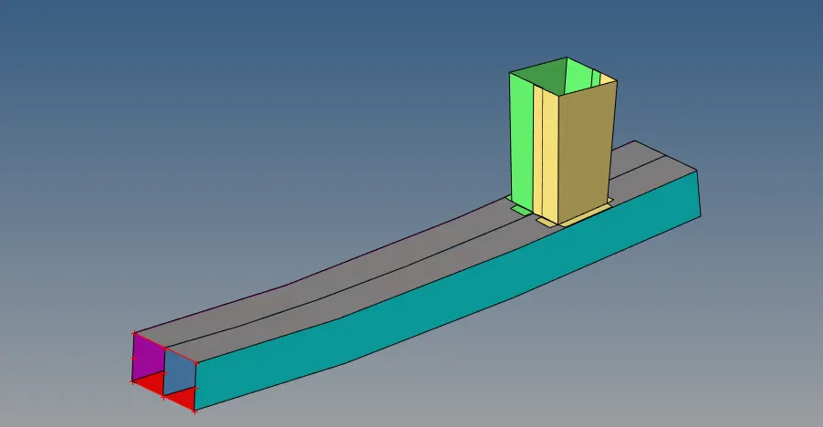
Assign quality parameters as follows: Click on Preferences in the Standard Menu bar >> to provide the Criteria. Select Criteria Menu Settings >>. Enter 6 mm as the target element's length. Select "Ok."
Meshing: Using the 2D panel, select the Auto mesh option to perform a mesh. To mesh, click the Surface. Enter 6 as the element size. Toggle mesh.

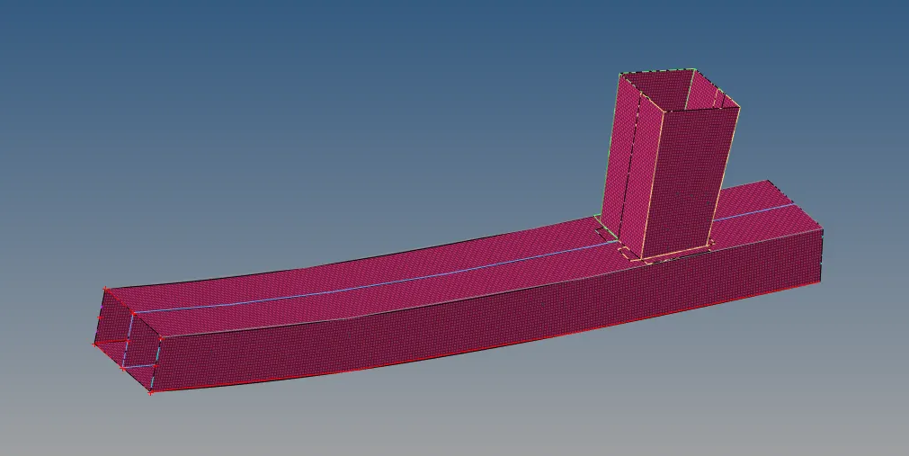
After the mesh is finished, the model is checked to make sure it is free of tria components. Establishing appropriate connections.
Now, use spot weld to join the crash boxes to the bumper. Navigate to 1D > Interfaces > Spot > Spot. Pick the crash box's nodes using the location selector.
Choose the parts that need to be joined, including the rear bumper and crash box. Put in 2.5 for search tolerance and 2 for the number of layers. Click "create" after selecting "type as weld with diameter = 2".

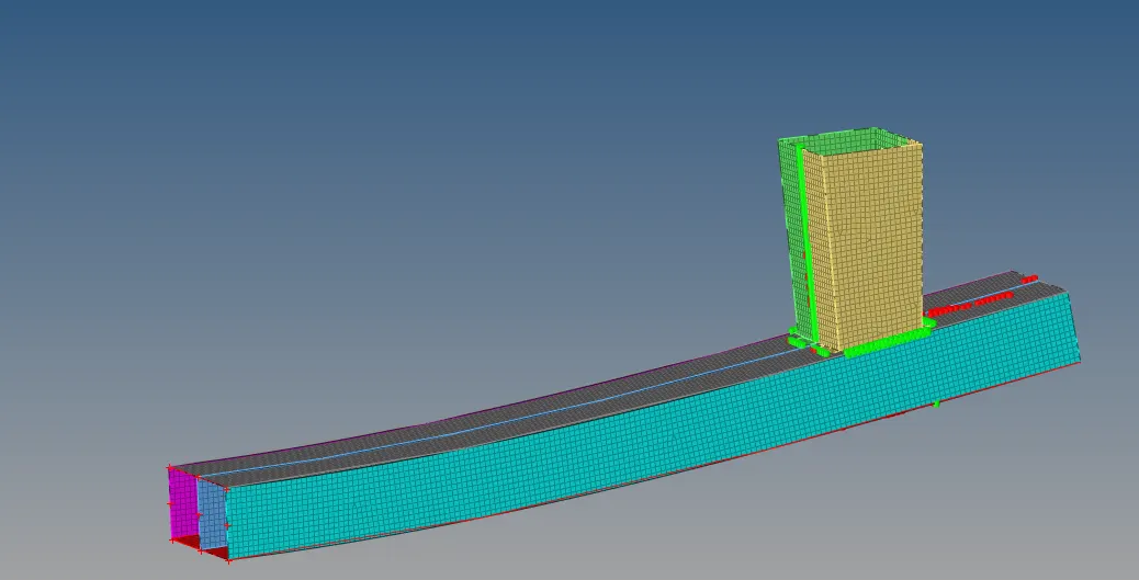 Connect the crash boxes in the same way.
Connect the crash boxes in the same way.
As a result, the bumper is meshing, and 1D connectors are used to attach the crash boxes to the bumper
Case 1 : Run the crash tube model as it is.
- The simulation must be run without making any modifications to the model in this instance once it has been imported
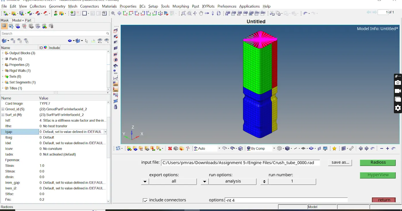
- Go to the Analysis tab and choose the Radioss option to simulate the model. Choose where you want to save the file. Verify the "include collectors box" > Select the settings tab and enter "-nt 4" > Press Radioss.
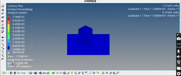
- To see animation and contour plots from an H3d file, use Hyperview. The following GIF displays the simulation.
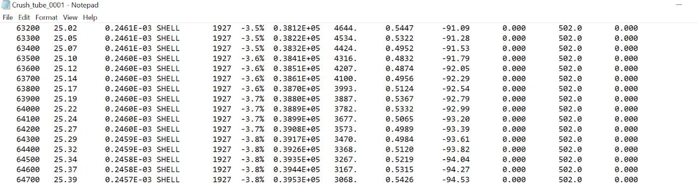
Check the mass and energy errors by opening the output file.
We may accept the results and use hypergraphs to depict the graphs since the output file shows that the mass error is 0% and the energy error is -3.8%%, which are less than -15% to 2% and 1%, respectively.
You may view the energy plot data from the T01 file by using hypergraph 2d.
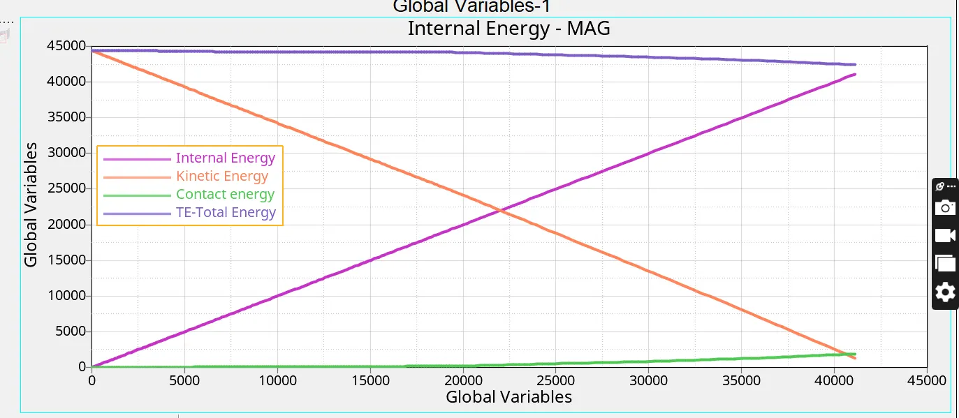
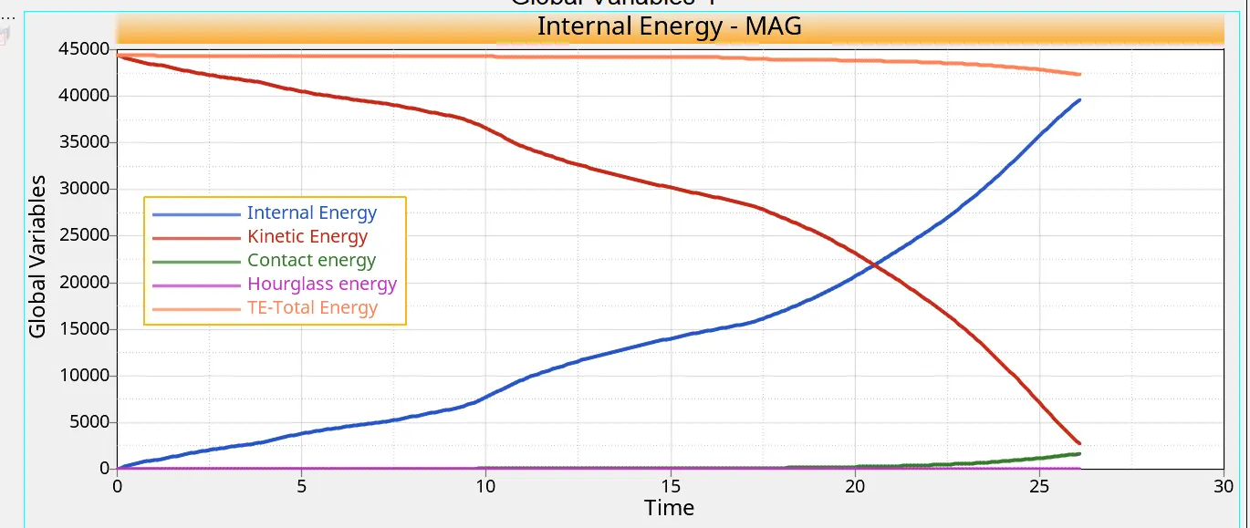
The graph illustrates how the kinetic energy peaks at the beginning and then begins to decrease as soon as the crush tube hits the stiff wall. As the crush tube deforms, this energy is transformed into strain energy.
As demonstrated by the system's increased internal energy. The energy error is within an acceptable range at -3.8%. The graph illustrates how the contact energy uses a portion of the overall energy. As total energy
decreases when contact energy rises. Distance adjusted to prevent penetration times contact force equals contact energy. In essence, the energy needed to enable a contact force to prevent penetration is the contact force. This
Should be minimum. As can be seen above, the contact energy is quite low for the majority of the simulation, and it slightly increases towards the conclusion.
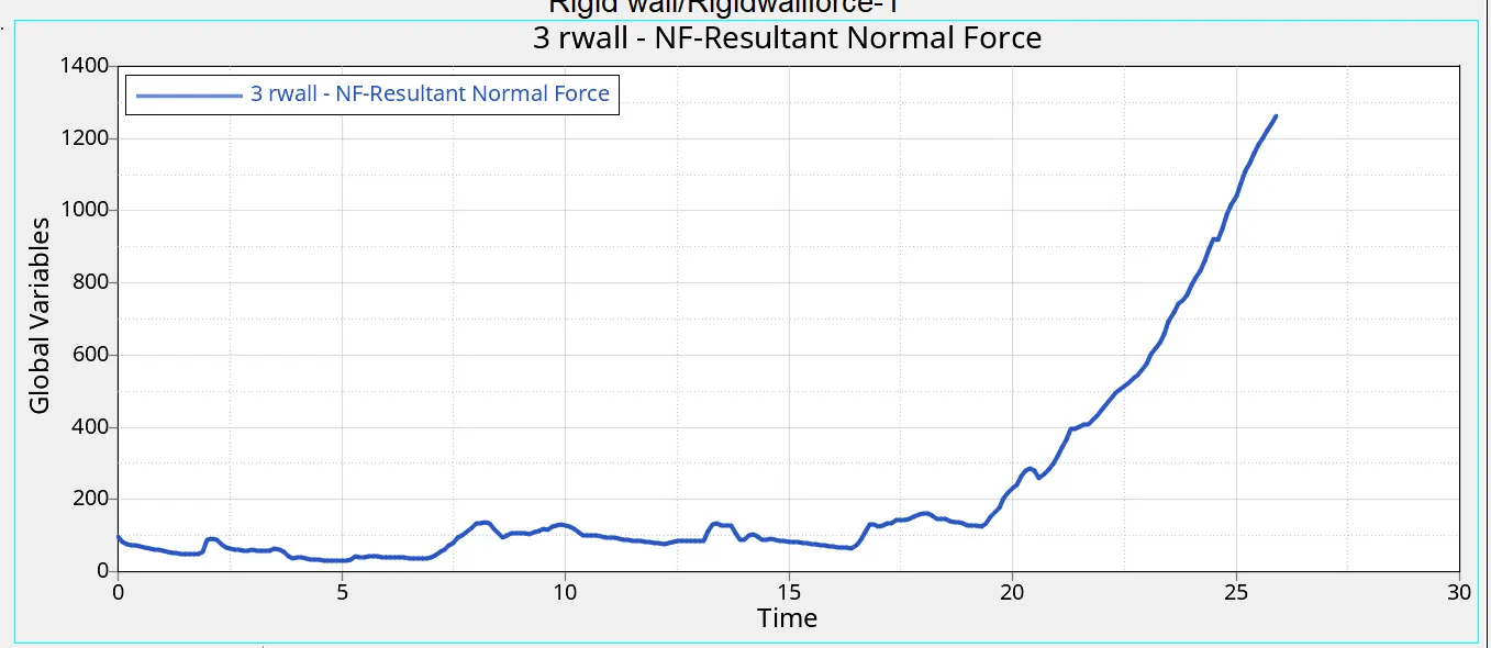
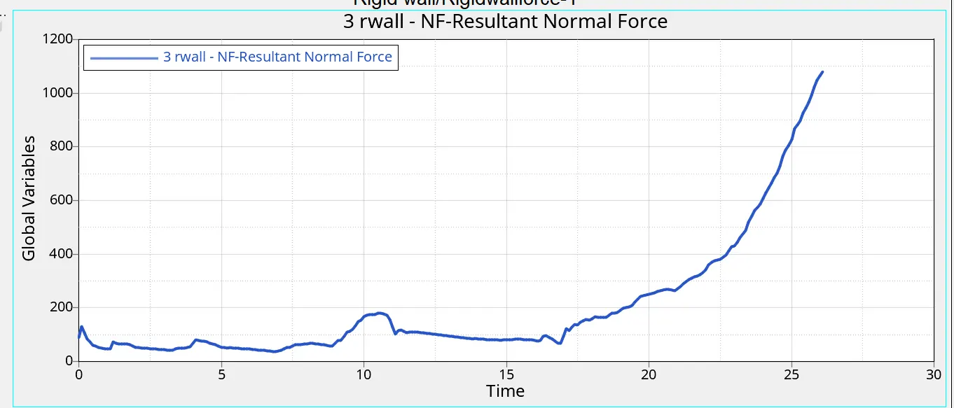
After T=25, there is an abrupt increase in the peak stiff wall force value for rigid walls. At this point, the crush tube has completely broken, leaving the distorted model with no more room to deform.
Is pushed against the wall at a certain speed, causing the stiff wall to respond.
Case 2 : Change the Inacti=6 and run.
In this instance, the issue statement requires that we modify Inacti = 6, therefore the model is imported and the simulation is conducted with the suggested properties. As seen in the Figure, the Type 7 contact interface is utilized with suggested properties.
Run the simulation after adjusting the parameters, following the identical procedures as in the prior instance. The following GIF displays the simulation. Plot the energy graphs according to the scenario above.
Compared to instance 1, the energy graph and the type of deformation are similar. An tolerable energy error of -3.8% is found.
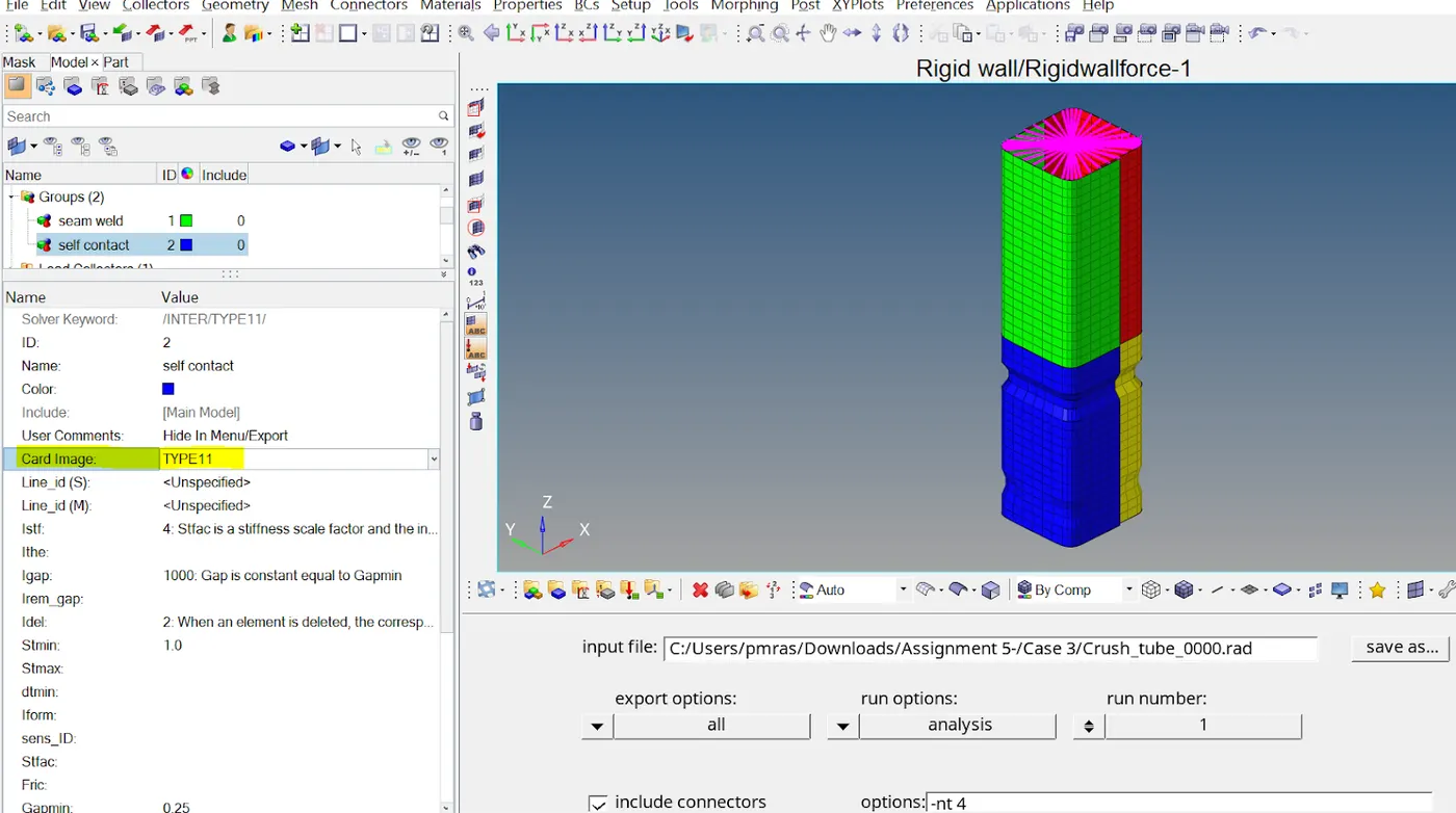
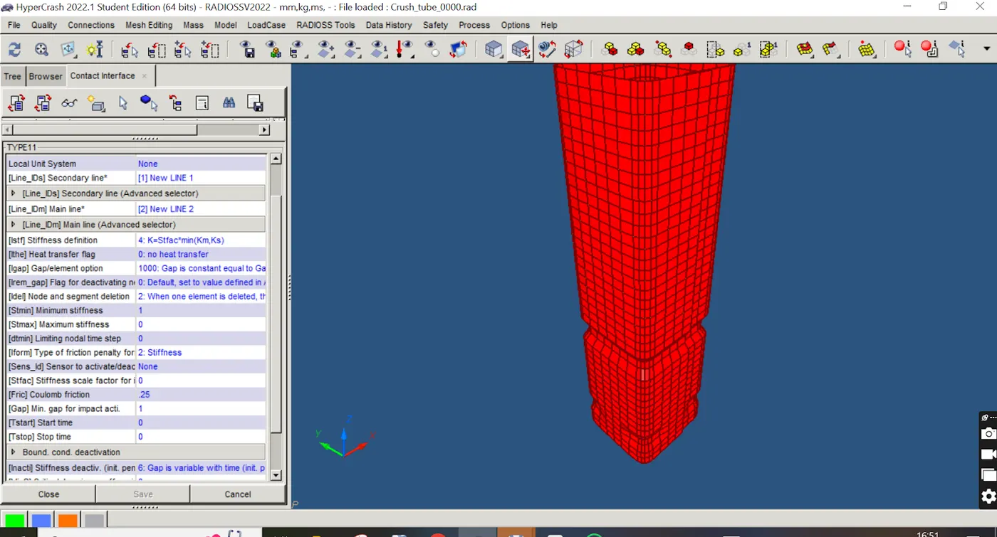
Interfaces of Type 7 employ the penalty technique, treating the behavior of slave nodes and master segments as springs that produce resistive force in response to penetration. Sort 11
Functions similarly to Type 7 in terms of gap definition, search methodology, and penalty formulation.
Once all the suggested values have been set (the same as Type 7), we can export the file, open it in Hypermesh, and begin the run.
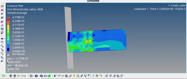
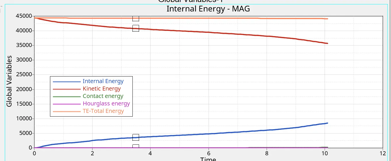
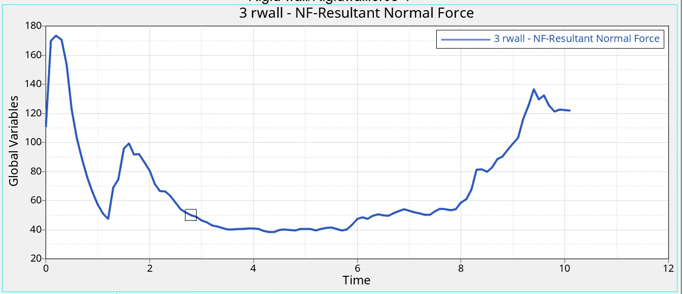
Similar to the preceding instance, the deformation and energy graph natures are also present here. The first part to distort is the notched area. The energy error is within an acceptable range at -3.8%.
Case 4 : Remove both notches and remove boundary conditions on rigid body nodes then run.
Here, we must execute the simulation after removing the rigid body's boundary conditions and notches. We may utilize the align option from the node edit option under to get rid of the notches.
Geom webpage. Navigate to Geom > Edit Node > Align. Choose two nodes (black) in the first and second end selectors, respectively. These choices will establish a line that the selected nodes on the notch (white) will be put along.
Hence taking the notch off. Press the align button. As can be seen here, the nodes will be lined up. For the full notch, follow the same process.
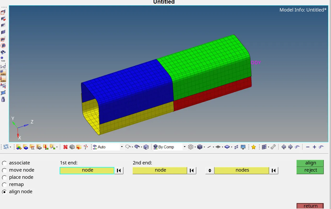
Go to the Solver Deck now to remove the boundary conditions. If the Solver Deck is not available, Select the View tab from the Standard menu bar, then click Browse, HyperMesh, and Solver to access the Solver Deck. Remove the Solver Deck's BCS Entity.
Go to the Analysis Panel and choose the Radioss Option > to start the model's simulation. Choose the location where the file should be saved (Note: Save the file in a different folder called Case 4 so that it will be simple to verify the models) > Verify the "include collectors box" > Select the settings tab and enter "-nt 4" > Press Radioss. The simulation executes without error.
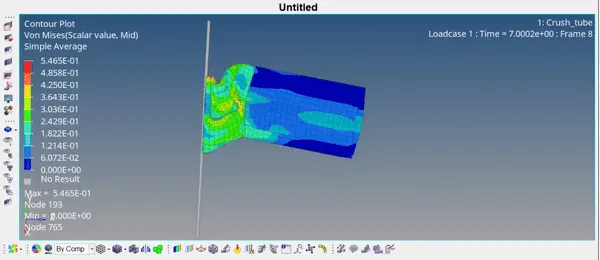
The crush tube is not notched, as may be seen above. Since there are no notches present, the deformation proceeds as predicted and there is no localized distortion during impact. The energy graph's nature is likewise comparable to earlier cases. The energy error is within an acceptable range at -2.4%.
Case 5 : Create a new notch in the middle ,select the whole section and run.
In this instance, the simulation must be performed and a new notch must be made in the center. By utilizing the translate option found on the Tool tab, we can generate a notch.
To correctly cut the notch, using the N1, N2, and N3 choice to specify the translation plane. Make the notch by translating the nodes by 4 mm. Once completed, run the simulation.
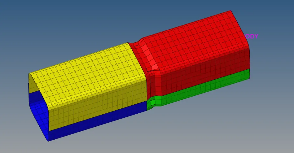
Go to the Analysis Panel and choose the Radioss Option > to start the model's simulation. Choose the location where the file should be saved (Note: Save the file in a different folder called Case 5 so that it will be simple to verify the models) > Verify the "include collectors box" > Select the settings tab and enter "-nt 4" > Press Radioss. The simulation executes without error.
Also here, after impact,deformation is first observed in the middle in the portion where the notch is.
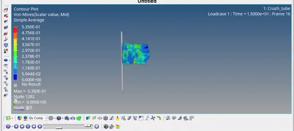
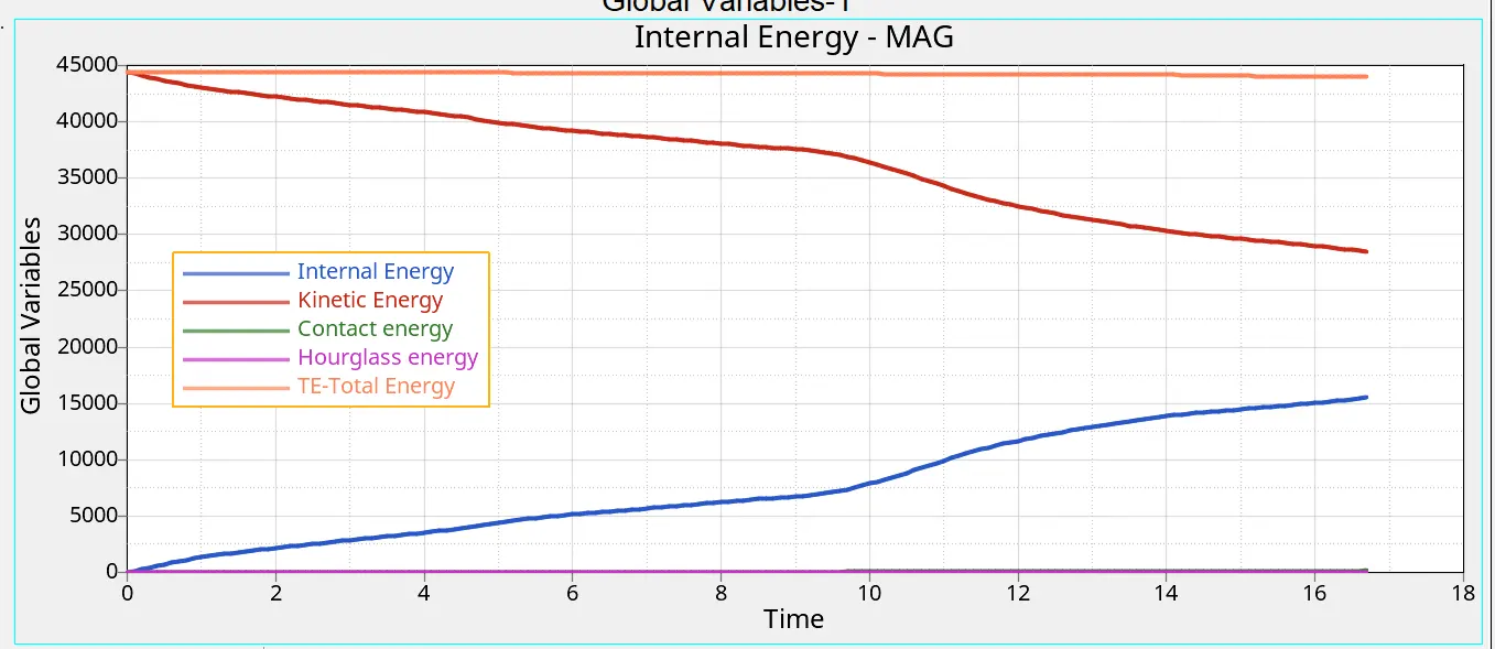
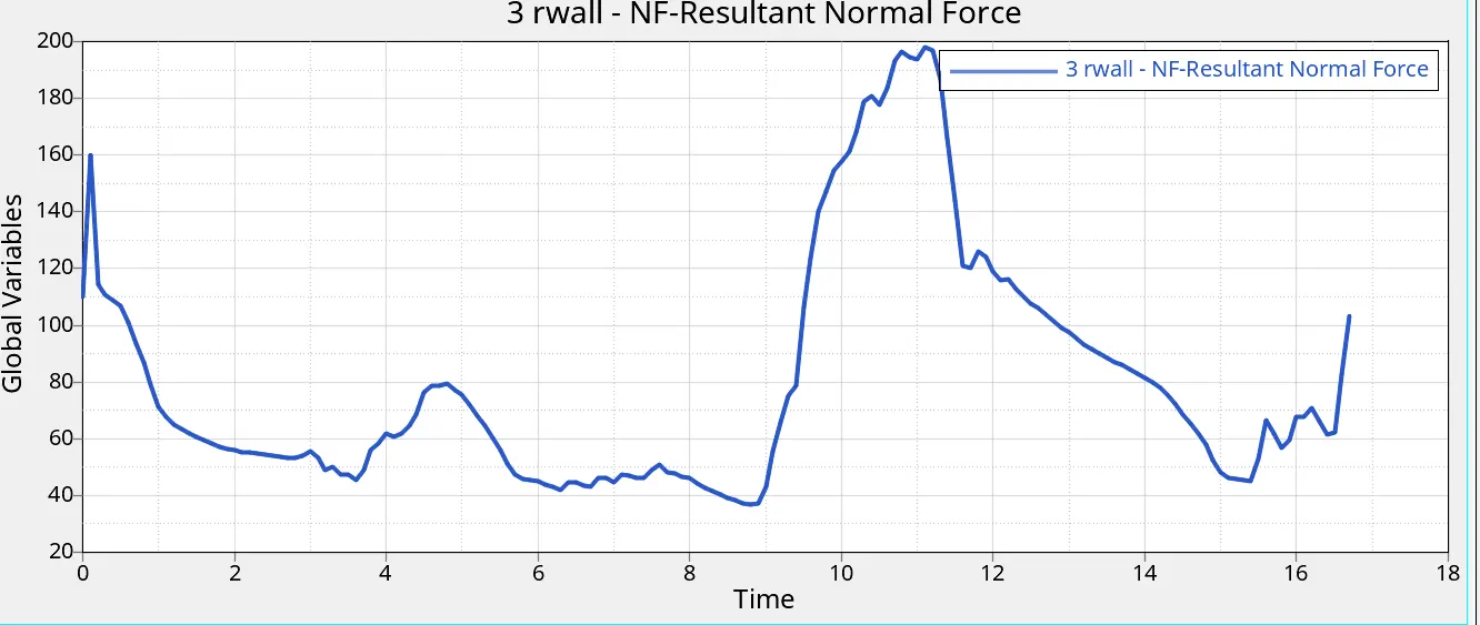
In comparison to earlier situations, the energy graph and the type of deformation are similar. The energy error is within an acceptable range at -2.3%.
Case 6 : Create a new notch with nodes only from opposing 2 faces and run.
In this instance, a notch made in the other direction should be made at the same location.
Once more, the Translate option is employed to raise the stakes.
Access the Tools panel and choose the Translate option. Choose the Nodes to translate > Choose the Element Orientation (i.e., the direction in which the elements should be moved) > Assign a magnitude of four (distance between nodes).
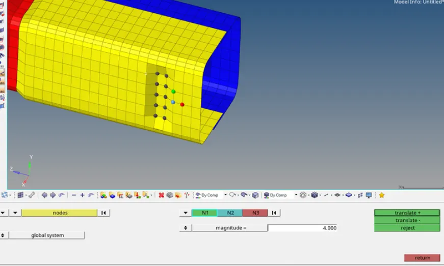
Go to the Analysis Panel and choose the Radioss Option > to start the model's simulation. Choose the location where the file should be saved (Note: Save the file in a different folder called Case 6 so that it will be simple to verify the models) > Verify if the collector's box is included. Select the settings tab and enter "-nt 4" > Press Radioss. The simulation executes without error.
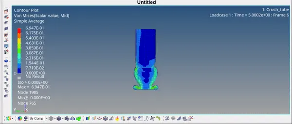
First, deformation is seen in the notched area, and the energy graph resembles earlier examples in most circumstances. About a -3.5% energy miscalculation is acceptable.
Conclusion :
It is noted that, in comparison to the other situations, the crush tube experiences the least amount of stress in case 4, when the notch is eliminated. Stress concentration occurs in the crush tube with notches, and these
Regions experience deformation first. When components are notched, the deformations are predictable. In example 1, where Inacti = 0, there is no initial penetration seen. If there was early penetration,
The graph of contact energy, which would have accumulated early on before any effect, might have served as an indicator. The allowed range of energy inaccuracy for all instances is -3.8% to -2.3%.
The notch is the cause of the shift in internal energy. The internal energy drops when the notch is removed, which also lowers the energy error.
High strains cause the notch regions to deform first. Stress levels are minimal at the planar surface when the notches are eliminated. Therefore, we can say that cutting off the notch aids in lowering the amount of stress the body is under.
A 3 mm shell needs more internal energy than a 2 mm shell, which indicates that the 3 mm shell can absorb force more readily. A component with a thicker shell has greater internal energy. Assignment 5 : https://drive.google.com/file/d/1eNTPhdPxyygggg4A_Njoe_3kfZ_JrpPN/view?usp=drive_link