Assignment 5-RADIOSS Interfaces & Study of Effect of Notches Challenge
OBJECTIVES-
1) to mesh the given bumper assembly with a mesh size of 6mm.
2) to carry out simulations on the given crush tube model, so as to compare result as per the following requirement of each case.
a) run the crash tube model as it is.
b) change the inacti= 6 and run.
c) create the type 11 contact and run .
d) remove both notches and remove boundary condition on rigid body and then run.
e) create a new notch in the middle , select the whole section and and run.
IMAGES OF MODELS-
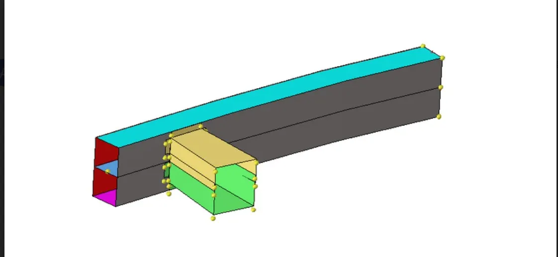
bumper assembly-
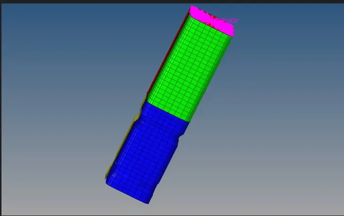
crush tube-
PROCEDURES-
MESHING THE BUMPER ASSEMBLY-
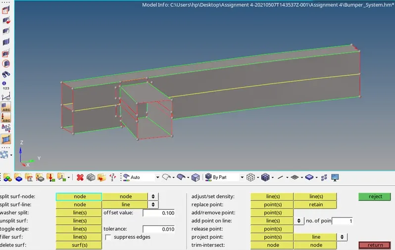
1) after importing the bumper assembly on hypermesh, the first step is to carry out geometry cleanup using the various quick edit tool( geometry>quick edit) , also geometry> surface edit > extend is used to ensure panel in the center intersect the outer panel to create the non-manifold edge that is in yellow colour . after cleanup is carried out , it should like this.
2) after cleaning up , we can set up to meshing.we can assighn the mesh quality criteria via prefrences> criteria file settings and as. the value as follows.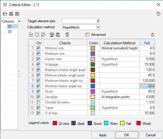
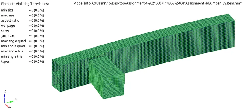
3) we can move onto meshing via 2D > automesh in the bottom panel. since all the componets have rectangular forces , we can directly mesh face without having to split up to avoid trias . with the mesh size is set as 6mm in the automesh menu , this is meshed assembly.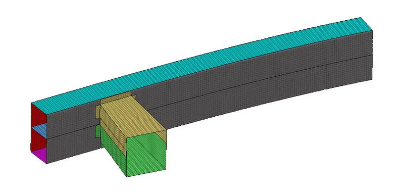
4) this is just one side of the bumper , we can use reflect tool to replicate the other half of it. reflect tool can be accesed via tools > reflects. selecting the axis along which is to be reflected and the base point , along with the all the element are duplictaed, we can go ahead and click reflect genertae the other half.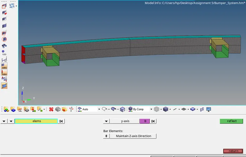
after this, we need to equivalance the mesh in the centre in since they wont be connected. this is done using tools > Edges. we can select all the element and adjust the tolerance find region that lack equivalancy . after highlighting them using preview equivalancy. we click the equivalance and finish them.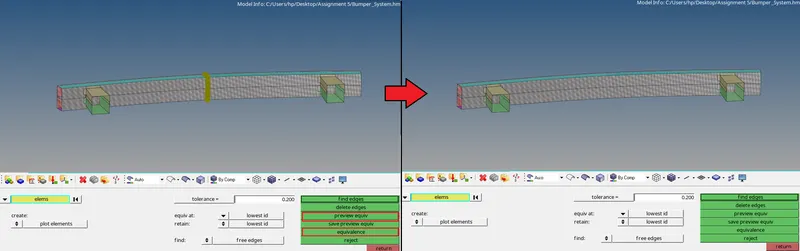
Running simulation on the crush tube-
there are 6 cases to be carried out and all of them mostly common procedures, expect the interface /model chamges, which are outlined as follows-
1) the crush tube model will be imported into hyperwork via the 'import solver deck' option in the upper toolbar, or through file > import solver deck.
2) as per the given requirement, the changes shall be made in this step, either through the model browser in hyperwork, or by switching to hypercrash via applications > hypercrash in the upper toolbar. specific instruction will be explained with in each case.
accsesing hypercrash-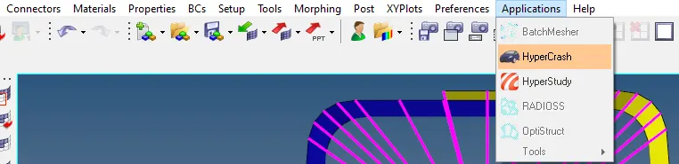
3) after the changes are made, we can move to the analysis section in hyperworks and select 'radioss'( if the hypercrash was used to make changes, the model is to be exported first through the file > export in hypercrash. then it is imported to be again in hyperworks, after which the radioss tool can be accesed)
4) before carrying out radioss analysis, we can go ahead and create the TH/PART. this only needs to be done once, for the first case, this will be reflected on the remaining cases since each case will be making use of starter file from the previous case.
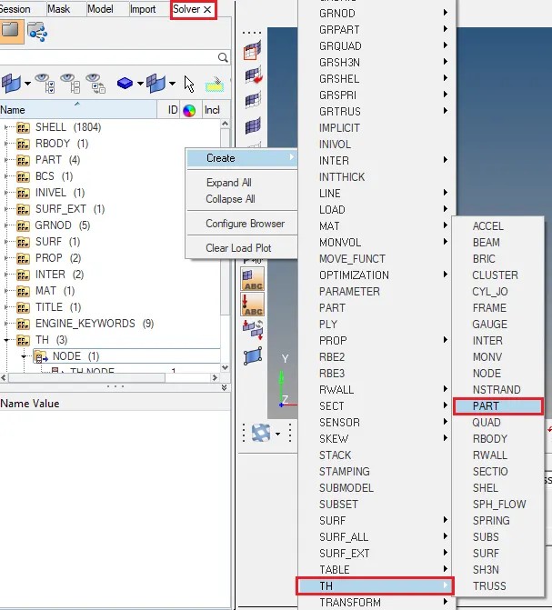
firstly, we can move to the solver tab. this can be enabled. through view > browsers > hypermesh > solver. then, we need simply need to right - click in the solver interface and go to create > TH > PART to create TH/PART.
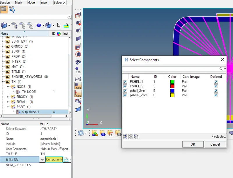
whle editing the TH/PART atributes, we need to component as shown.
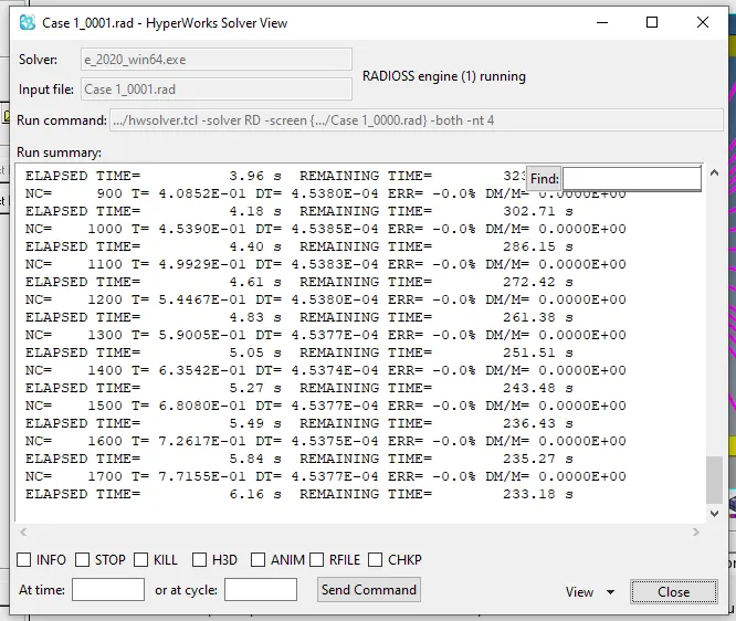
5) in the radioss section , we can click save as to save file. if it is hasn't been saved yet. care must be taken to include_0000.rad in the file name since it is a starter file . after that , we check the connector option and inpurt -nt 4 in the option bar clicking radioss. this start the radioss. this start the radioss simulation , which will run for few minutes.
6) simulation complete , we can switch to hyperview through the client selector.
in hyperview , we wil to be import h3d variant of the file. after importing we can then select the contour tool to switch to the von mises contour we so can analyze the stresses that form within the crush tube in the simulation.
7) next step to carry the energy error and mass error checks and this is done by analysis the RADIOSS engine output file . this can be accesed from the same directory as the starter and engine file and is denoted by the .out extension . we need to the check the file that containes _00001.out by using a any text editor.
8) we can then go ahead and generate the plots , using the same client selector. we can switch to hypergraph client . we are asked to import the required file . it is the t01 varient of the file. on importing we can build the plot using the variables of the plot.
CASE 1- RUN THE CRASH TUBE MODEL AS IT IS-
for the first case we can required to the run the simulation of the crash tube as it. the instruction outlined perviously are as followed. in the case we disscusing the type 7 interface when inacti is set 0(default) in hyperview. the following simulation can be seen.
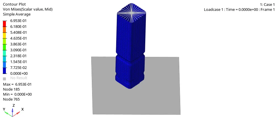
from the above animation , it is evident that the present of the notches result in stress concentartions in this regions and as a result, buckling occure there first , this will happen in all following cases involving notches . the region below the highest notch is completely deformed first . after the deformation of the lower part , the buckling moves onto the upper part, where buckling take part next untill the crushtube is completely sandwiched between the rigid wall and the source of the force application.
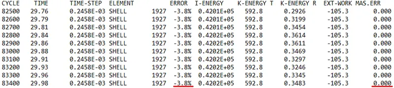
as we can see the energy error is 3.8%. is acceptable since it is below -15%. in addition to that. there is no mass error (0%)
taking the energy and rigid wall plots:
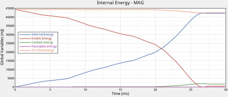
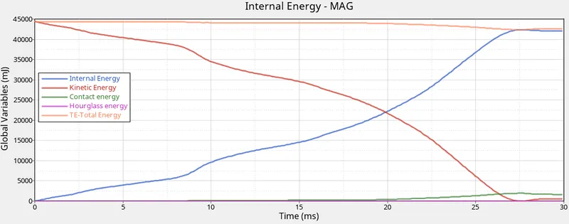
1)the kinematic energy goes on decreasing as per the buckling endured the crush tube. it falls to 0 at 27ms mark, meaning there is no deflection in the model at all that point. there is slight incrreases afterward slight du to reaction force of the tube.
2) internal energy keep increasing over the course of the simulation as expected. with the tube continuesly absorbsing energy, which in turn result in deformations . once the deformation was complete , it pleatuned around the 27ms mark.
3) contact energy is a type energy that is formed when one elements comes in contact with the other or neighbouring elements, the opposite force created by this element form the contact energy . in this case it increase after 20 ms at this point the full model is buckled in such way that penetration node occure. it entire tube pressing itself , buckled elements are forced into the contact . it slightly decreases and stabilizde after the 27 mark , proabably du to rebound disccused earlier.
4) the increases contact energy affects the overall energy of this system , which is why there is a decreases in the total energy at around the same time.
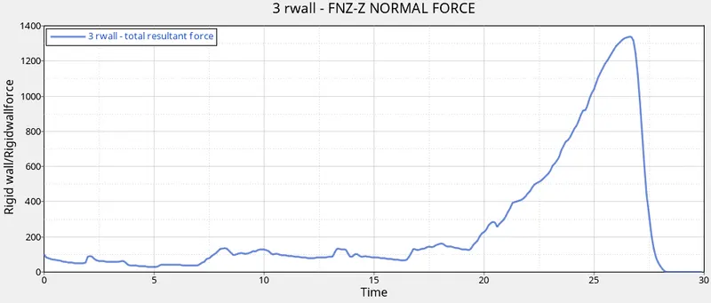
5) looking at the Rwall forces plot below, it is evident that the rigid wall immediately expreinces some odf the force . it slightly increases untill 20ms mark where the step increases in the force du to the crush tube having mostly deformed . it was not able absorb any more energy and this was being transfered to the rigid wall. after the 27 ms , the tube was deformed completely and that explains the steep decrases in Rwall forces.
CASE 2- CHANGE THE INACTI=6 AND RUN-
In this case , we shall be using hypercrash as well. so, continouing past the second step outlined in the procedure, we can import the given crush tube model using > import.
after importing, we can go ahead and switch to the model brower tab , after that move on to contact interface > self contact. we can then right click self contact and select the option in see in panel.
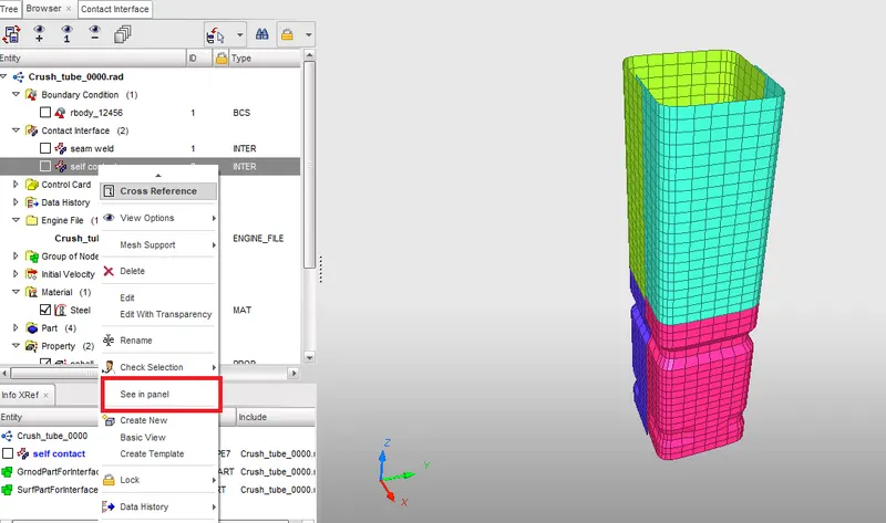
we can go ahead and change the inacti value 6, as per the requirement.
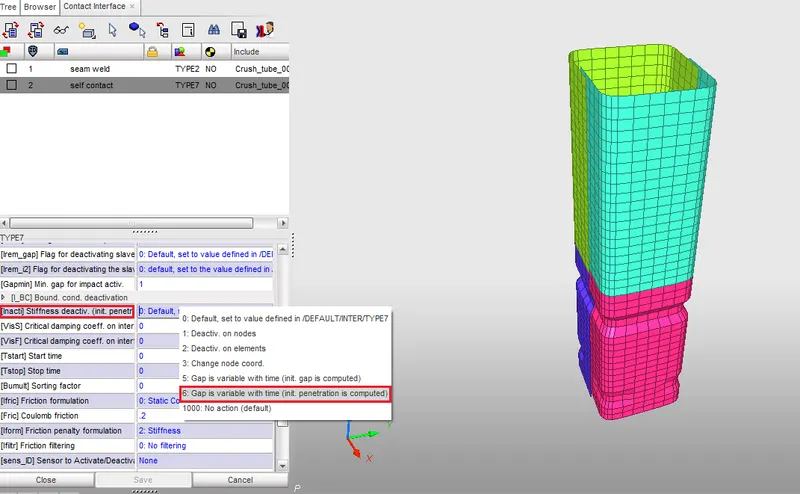
after that we can export the model with appropriate file name and continued to step outlined , after this saved model is imported again a hyperworks. after analysis , switching the hyperview.
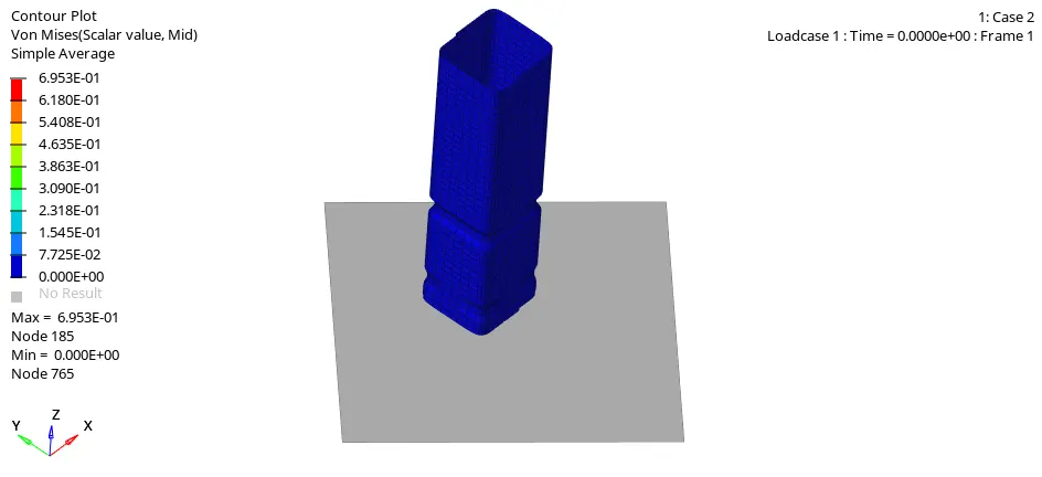
there is difference between case 1 and case 2 animations. they both similar .even through the inacti paramater was changed , they didn't effect on the simulation on there was initial pentration to manage in the first place.we can took in output file.
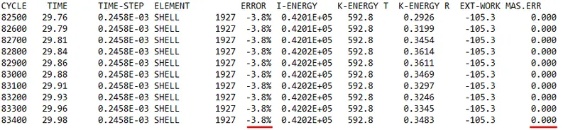
as we cam see. the values are in the same case 1. the energy error is the same -3.8% ( also the same mass error of 0%) moving on the plots.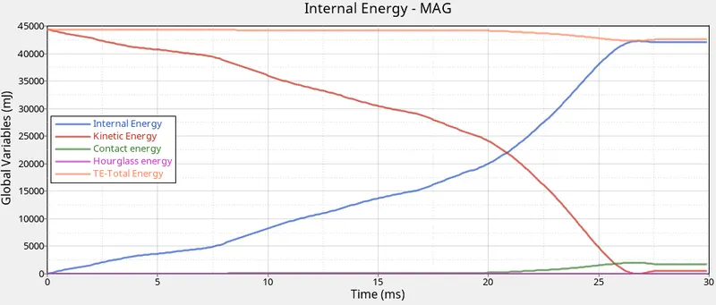 \
\
the only thing we have learned from the energy plot is that there is no initial penetratiion there is no difference between case 1 and case 2 energy plots. since the was tweaked to detect such penetration through the inacti function. the internal energy start from zero value.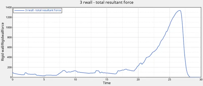
CASE 3- CREATE THE TYPE 11 CONTACT AND RUN -
in this case , we are to introduce the type 11 interface to the case 2 solver deck file. after importing it in hyperworks, following step 2 of the general procedure, we can are make to changes in model browser tab. the right clicking the section, we can select creatre > contact. after that, we can defines this newly created contact and assign in the following values.
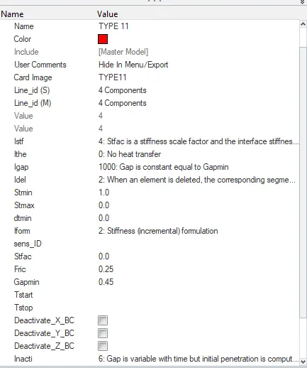
the both line_id(s&m) atrributes, all the component of the model will be selected. the other value are recommended setting for type 11. then a usual, the file can be processed using the radioss solver. the remaining steps as followed given.
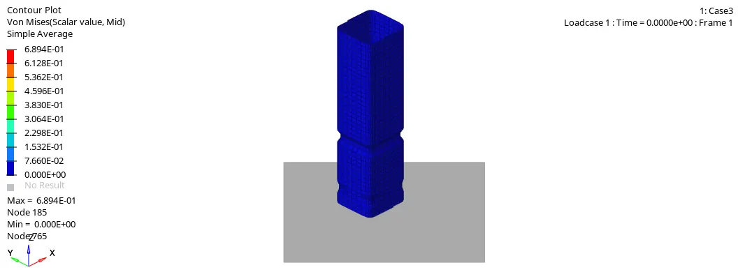
and the output file values.

energy error still with in the -15% limit at -4% mass error is not existant moving to the plot.
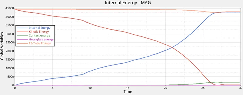
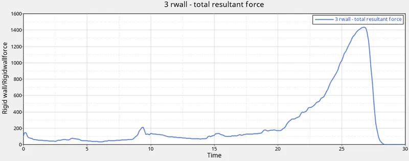
here the deformation characteristics are similar to ehat was observed in prvious cases. there is no discrinible difference between the energy and rigid wall plot of this case and previous cases. therefor we can conclude that there was no edge-to-edge penetration in this model.
CASE 4- REMOVE BOTH NOTHCES AND REMOVE BOUNDARY CONDITION ON RIGID BODY NODE AND THEN RUN.
For this case, we are required to remove the notches and boundary conditions. to that after importing the solver deck file (starter file for case 3. we can make use of one of the mesh edit function available on hyperworks- the aligh node tool (f7).
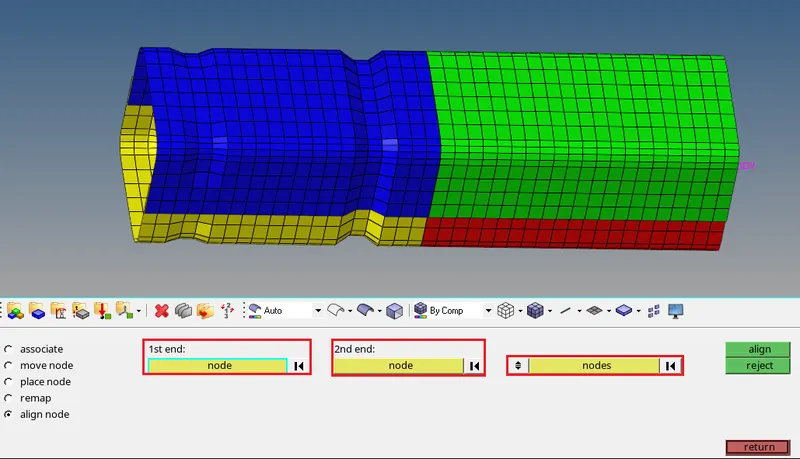
with this tool, we need select the 1st end and 2nd end - which are basically refernce point for node alignment. the algorithm. the algorithm pick the singular staright line running through these node and align that node that requirement , which in this case will be notch removable after that , we can save file as case4_0000.rad.
without notches-
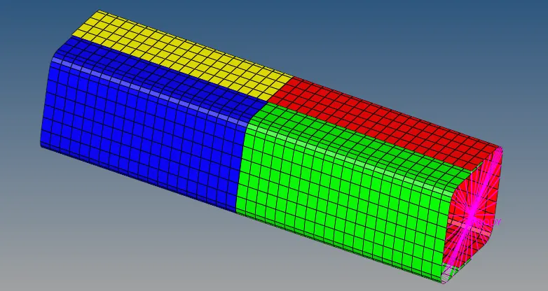
we can now switch to hypercrash and import case_0000.rad. moving on to the model broswer tab, right click boundary conditions and select delete. doing so removes the boundary condition as per the requirement for this case.
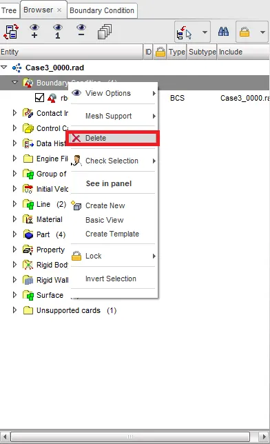
now we can export this file in the same name and continue to the radioss simulation procedure on hyperworks. the remaining the steps are the same continuting from step 3 in the main procedure as outlined before.
taking a look simulation.

the next to be energy plot-
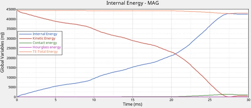
the kinetic energy decreases from maximum with an increase in internal energy. the chracteristics are similar in previous cases,with the the internal energy's slope increasing after the 20ms mark, probably du to most of the elemets du to buckling, and du to the fact that the crush tube almostly to be crushed , although compared to previous cases, the contact energy is slightly lesser. this pronbably du to the lack of notches in the model.
the looking at the rigid wall plot-
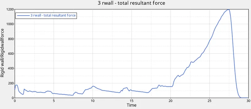
the model resultant force peak at almost 1200km. just as with in internal energy in the previous plot , there is a steep increase at 20ms mark here as well . at this point , a large amount of force is being transfered to the rigid wall considering the crush tube almost completely deformed to absorb any more energy.
CASE 5- CREATE A ANEW NOTCH IN THE MIDDLE, SELECT THE WHOLE SECTION AND RUN.
For this case , we shall be using the starter file case of case 4. so there are no notches or boundary conditions. but the case require us to create a notch through the middle section of crush tube for this , we shall be making use of translate tool in hyperwork, after importing the starter file hyperwork, we can go to tools > transalate.
we can either select elements or node to translate. after asssighning the direction of transistion ( using an axis or a vector ), we then need to assign a magnitude. depending on the global axis, we then have to either click translate+ or translate- this create the depression.
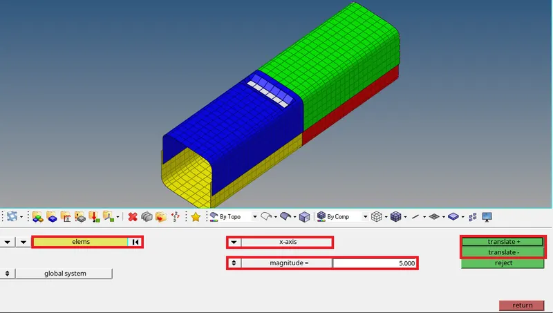
the process is repeated for each element in the same line ( for both layers whenever required ) to form the notch around the tube.
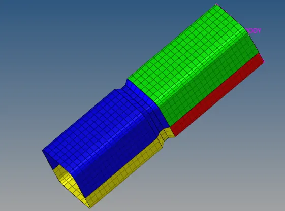
now, we need to the run the analysis through the radioss engine and generate the simulation. this what is look like.
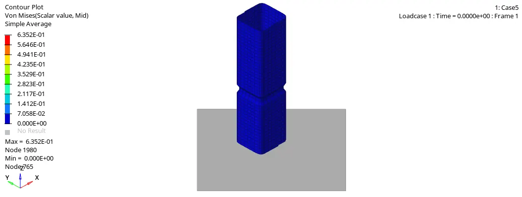
just as in the first 3 cases, the notch is the region where the tube undergoes deformation first. then the rigion closer to the rigid wall is deformed next, which would be the lower half of the tube. around the 10-12ms mark, when the lower half is mostly deformed, the upper half undergoes proper, visible deformation rapidly untill the entire tube is crushed completely. in addition to that, based on the nature on the notch, that may annomalies. since was created manually.
taking alook reading at the output file, we can see that the value are acceptable.\
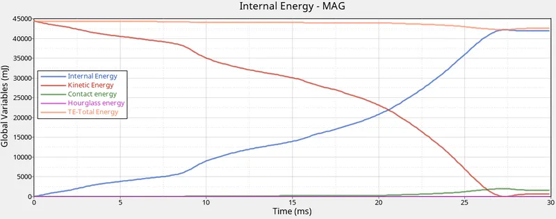
the moving the energy and rigid wall plots-
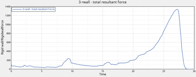
there is no inmmediate diffrence between case 4 and case 5 in this plot pattern other than the blip at around the 9ms mark for the rigid wall plot. this happens specifically du to the complete buckling of the lower half of the crush tube. there is small period where the tube transfer its capacity to absorb energy to the upper half and this characterized by the slight increase and decrease in rigid wall forces in that period.
as seen previously, the internal energy increases and kinetic energy decreases, and then contact energy is more noticebale at an earlier point in the time as compared the previous cases, this probably duto the depth of the notches facilating the buckling process.
CASE 6- CFREATE A NEW NOTCH WITH NODES ONLY FROM OPPOSING 2 FACES AND RUN-
for this case, we can make use of case 5's starter file and follow the same process of creating notches but instead for creating one all around the tube, we simply create two seprate notches on opposing faces of the crush tube, using the same translate tool.
now there are two sets of notches on the tube-
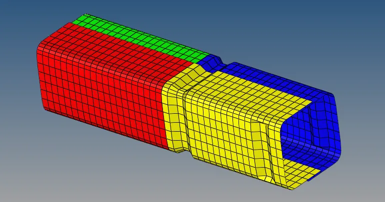
we can they carry out the analysis using radioss as outlined in the main procedure. the simualtion as follows-
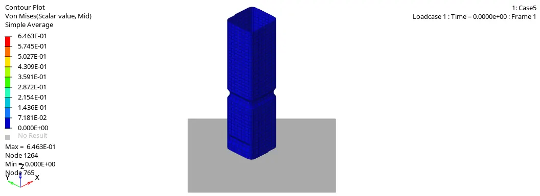
just as in the previous case, initial buckling take place along the notches and the overall deformation follows the same pattern. the region above the highest notch is virtually unaffected untill the 10ms mark when most of the region below the notches have been deformed. moving on to the output file readings.

they have acceptable energy and mass error values.
taking a look at the energy graph-
the rigid wall graph plot-
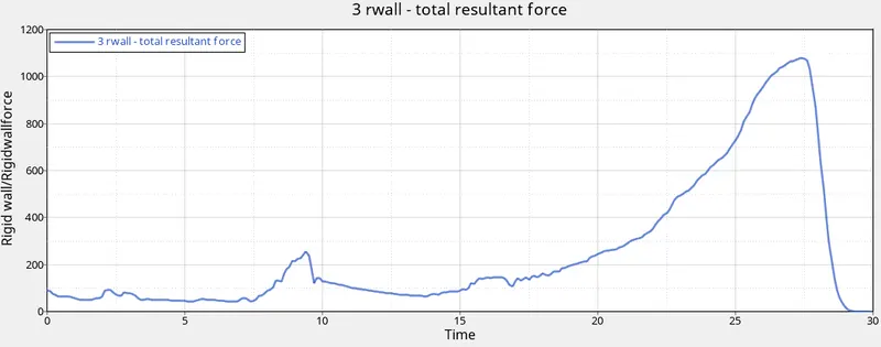
again, the plot are quit similar in nature to the earlier case , expect in the case of the rigid wall plot, the peak slightly around 1100kn, as compared to the peak in case 5 which is around 1300kn. probably du to the notches increased capacity of absorbsing forces. this case have more notches and that resulted in lower rwall peak. there increase in slope past the 20ms mark, probably du to most of the tube having undergone some kind of deflection/ buckling. at this point, the rigid walls startes bearing the brunt of the incoming the force.
OBSERVATION AND RESULT-
The given bumper assembly was mehsed as per the required mesh size of 6mm and it was also reflected to form the other half.
in the case crush tube analyse-
notches are the rigion where deformations happen first under duress, du to them being regions off stress concentration, but it does help to control and predict the location of deformation, this is turn playes a role in how the absorbed energy spredas throughout the tube. a notched tube result in higher contact forces but a smoother transmission load.
in this assighnment, diffrent type of contact were used to analyze the simulation of the crash tube. under a constant load , the behaviour observed by varying the geometry through the removal and creation of notches.