Assignment 5-RADIOSS Interfaces & Study of Effect of Notches Challenge
AIM
===================================================
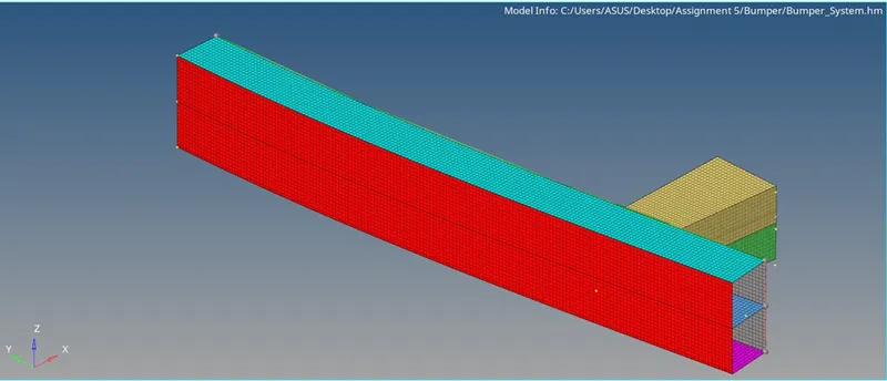
- Create the mesh on the Bumper model
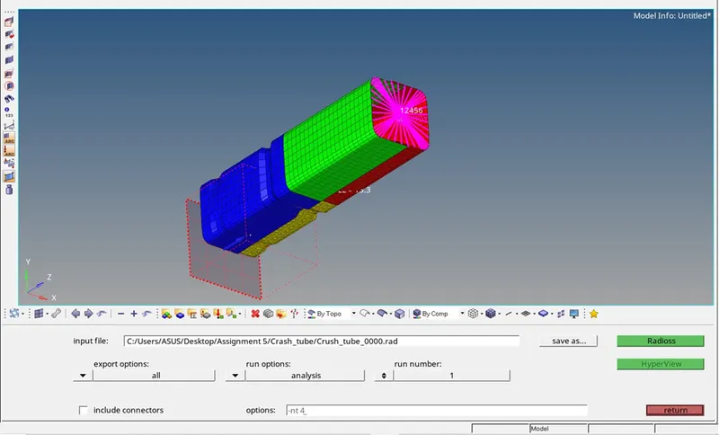
- Run the crash tube model as the instruction.
- Run the crash tube model as it is.
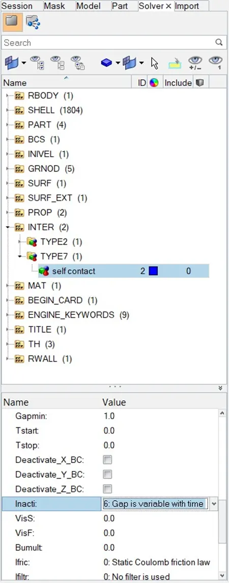
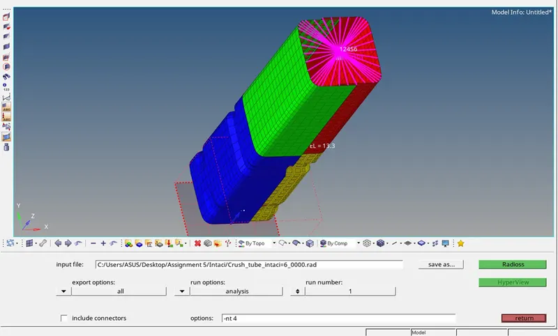
- Change the inacti =6 and then run.
- Create the Type 11 contact and then run.
- Remove both the notches and boundary conditions of rigid body node and run.
- Create the notches on the middle of model and then run.
- Create the nodes on the middle of model but only in 2 opposite faces and then run.
OBJECTIVE
===============
- Get knowledge about different type of contact definition in Radioss.
- Get knowledge about parameters of defining contacts.
THEORY
=========================
Contact modeling/ Interface modeling refers to the behavior of two different models when they come into contact with each other.
Different types of contacts are in table below:
|
Sl no |
Interface Type |
Description |
Purpose |
|
1 |
Type 7 |
General node to surface |
Crash structure applications |
|
2 |
Type 11 |
Edge to Edge |
Crash structure applications |
|
3 |
Type 24 |
General node and surface to surface |
Crash structure applications |
Parameters:
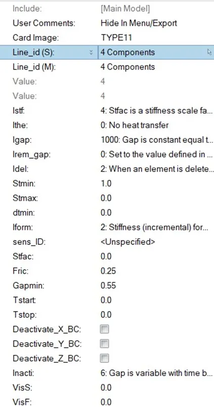
- Igap: Determines how the size of the gap is calculated.
- Gapmin: Minimum gap for activation of interface.
- Inacti: Action to take if initial penetration exist.
- Istf: Affects how the stiffness of interface is calculated.
- Iform: Frictional formulation.
- Stmin: Minimum stiffness to use in the interface.
- Idel: What to do with the slave nodes and master segments if element fails.
PROCEDURE
=================
Meshing of Bumper model
- Crash tube model run
Analysis < Radioss < Radioss
- Change inacti =6
For changing the inacti
Solver Browser < INTER < TYPE 7 < Self contact < inacti =6
After altering inacti run again
- Create TYPE 11
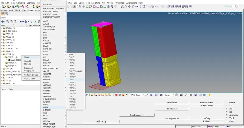
Open the previous model and create the TYPE 11 contact.
Right click on solver browser < Create < INTER < Type 11
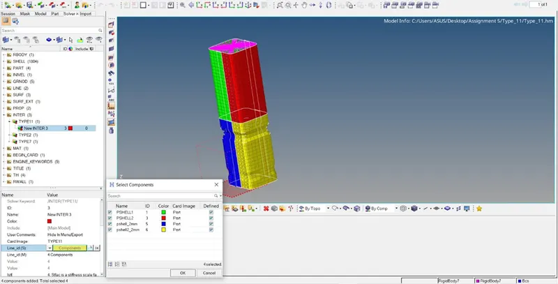
After creating components are selected
Solver < INTER < TYPE 11 < New Inter3 < Line_id(S) < Component < Select all
Solver < INTER < TYPE 11 < New Inter3 < Line_id(M) < Component < Select all
Here the both the surfaces are same because contact is defined as self contact.
Parameters are filled as followed
- Remove the notches and boundary conditions
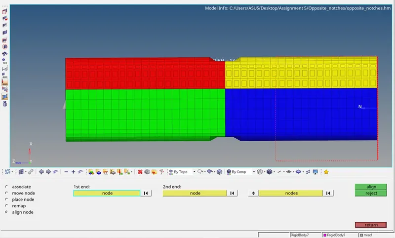
For removing the notches Align nodes are used
Geometry < Nodes edit < Align node
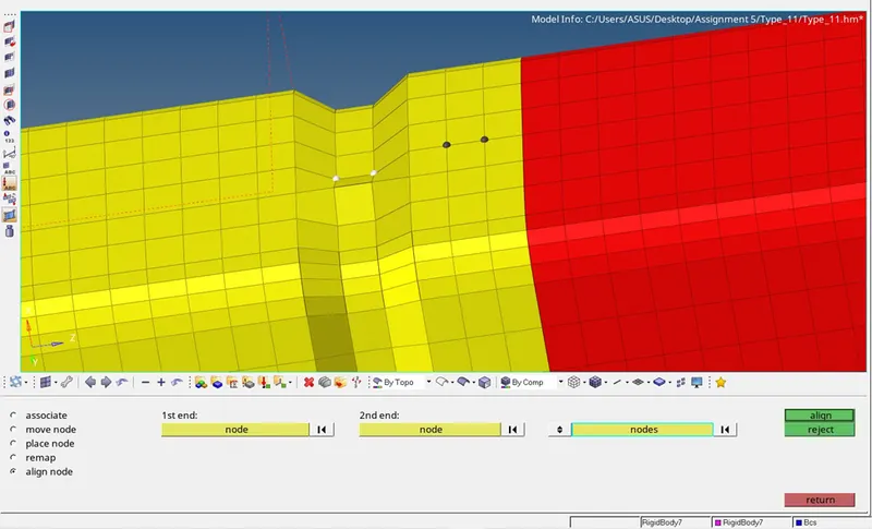
Final model looks like
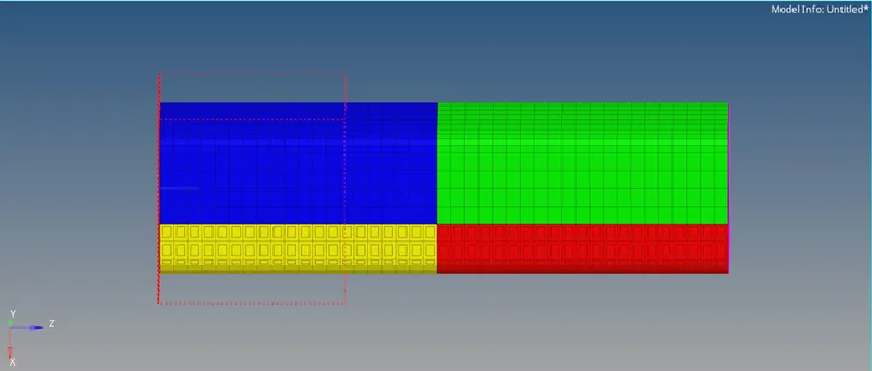
Now boundary condition is removed .To remove the boundary condition simply delete the BCS card.
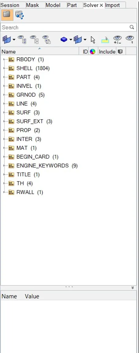
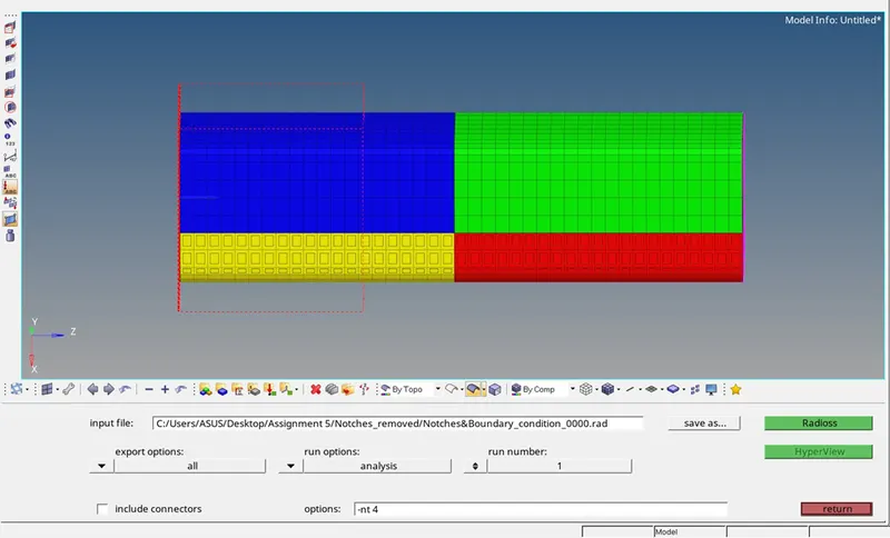
Now the analysis is done
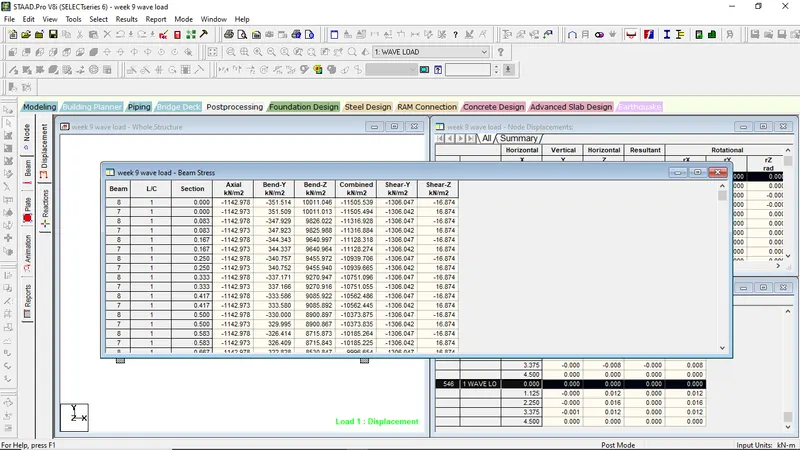
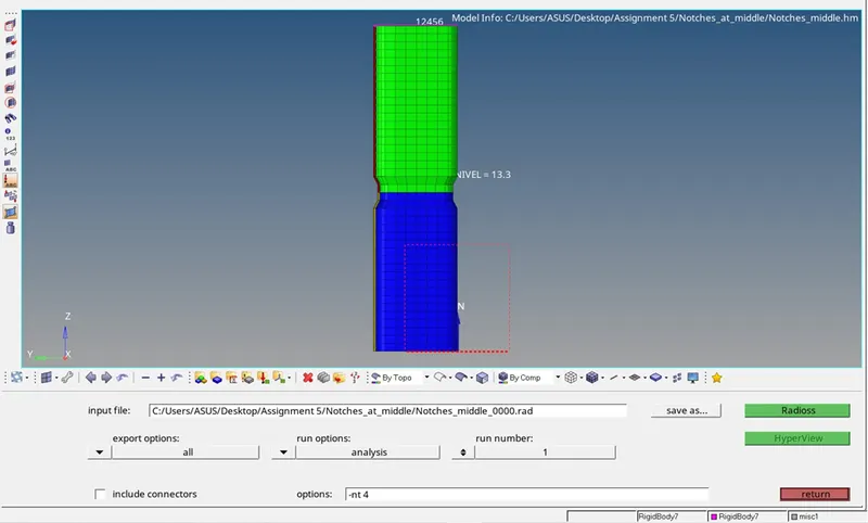
- Notches at the middle of model
Again the notches are formed at the middle of model and model was run again.
- Notches at the opposite side of model in middle
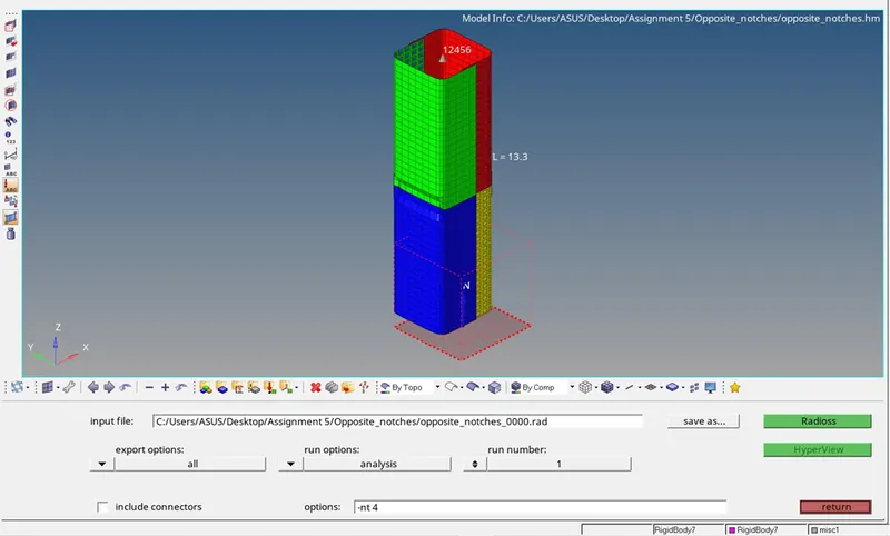
Here also notches are created by the align node method in opposite side.
CONCLUSION
=======================
|
Sl no |
Description |
Plot |
|
1 |
Type 7 basic |
 |
|
2 |
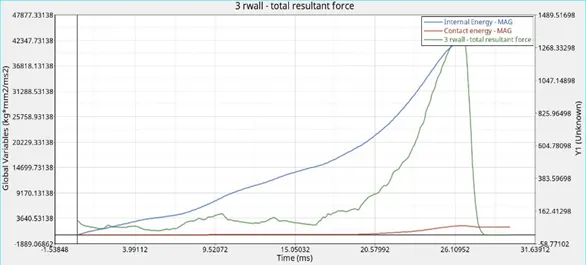
Type 11 |
 |
|
3 |
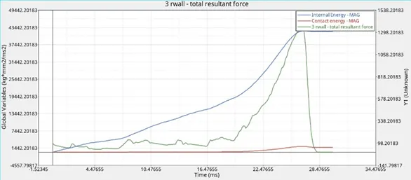
Type 7 Inacti=6 |
 |
|
4 |
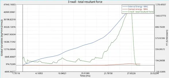
No notches and boundary conditions |
 |
|
5 |
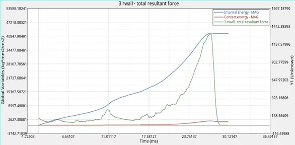
Notches at middle |
 |
|
6 |
Opposite notches |
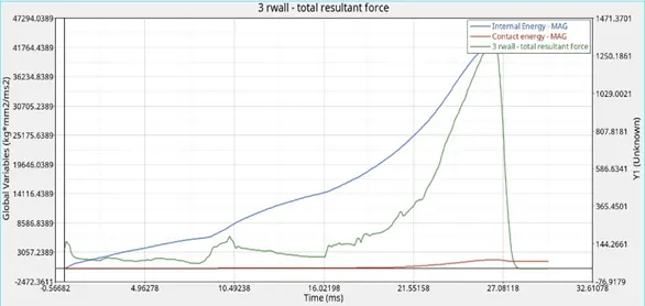 |
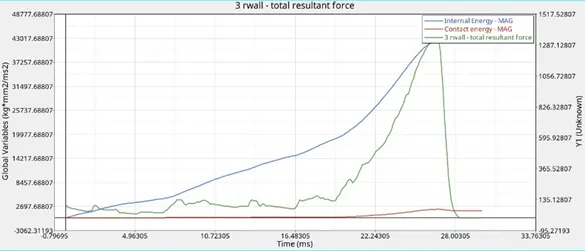
From the above plot it is evident that for Type 11 contact energy is maximum and when boundary condition and notches are removed it is minimum.