Assignment 5-RADIOSS Interfaces & Study of Effect of Notches Challenge
- Create the mesh for bumper assembly,mesh size should be 6mm.
- Run the crash tube model as it is.
- Change the Inacti=6 and run.
- Create the type 11 contact and run.
- Remove both notches and remove boundary condition on rigid body node then run.
- Create a new notch in the middle ,select the whole section and run.
- Create a new notch with nodes only from opposing 2 faces and run.
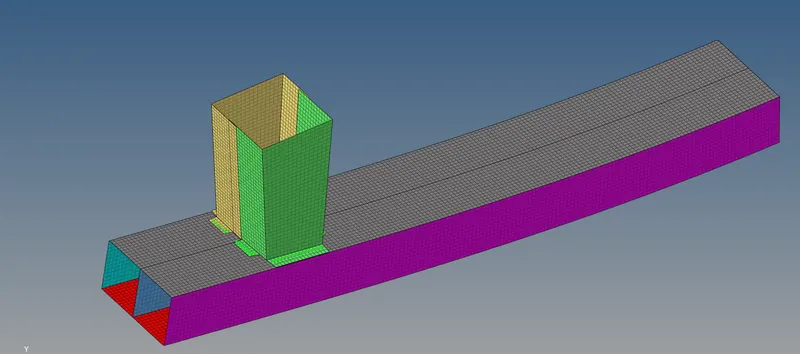
Case 1
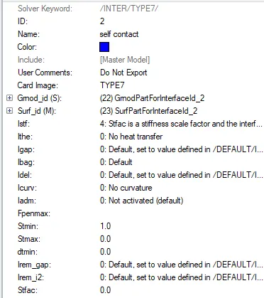
In case 1 the analysis was run without making any changes and the results were noted down. Here a type 7 contact definition was used.
Von-mises stress plot
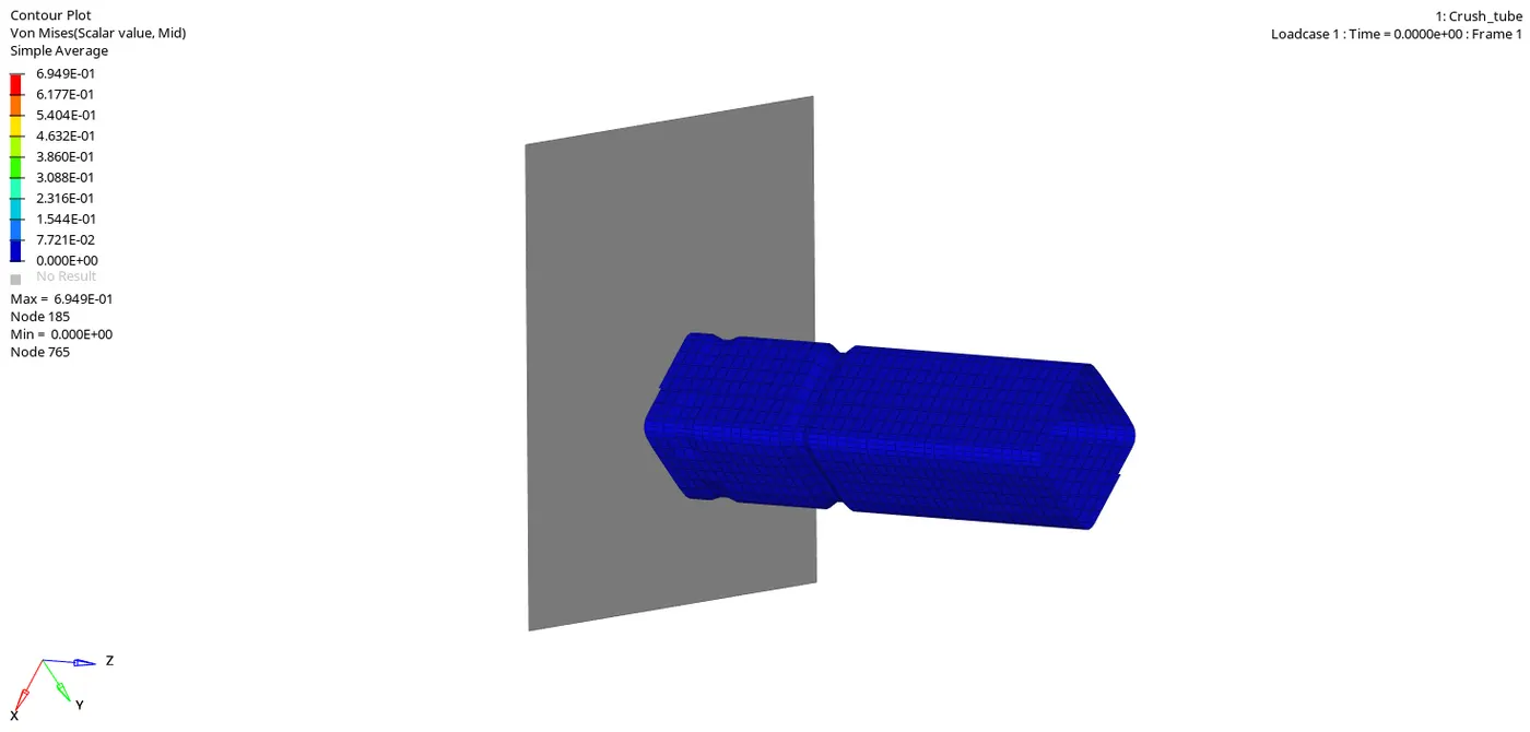
The maximum equivalent stress observed was found to be 6.94E-01MPa.
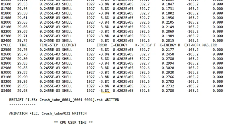
The energy error was found to be -3.8% which is with in the range.
Energy plot
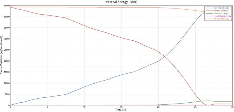
From the plot its seen that the kinetic energy is increasing and when the crash happens it declines and dips. In the same time a increase in the value of internal energy was observed in which kinetic energy is been converted to internal energy. The total energy remails constat for some time and the curves dips at the end Also there was slight increase in hourglass and contact energy were been observed.
Rigid wall force
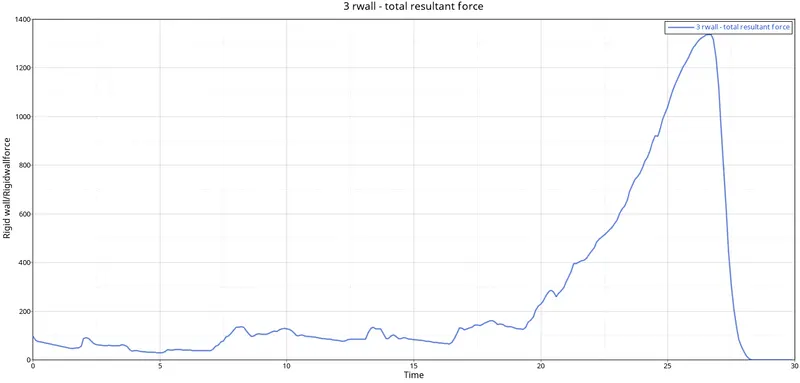
The maximum force observed were found to be 1337.9KN.
Case 2
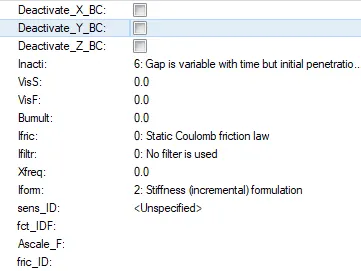
In case 2 Inacti option was used which will take actions if initial penetration exist. If its been kept at a value of 6 Gap is variable with time but initial penetration is computed.
Energy error
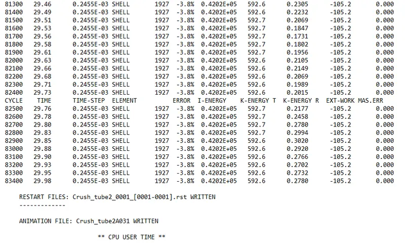
The energy error and mass error got from the simulation is with in the acceptable range.
Energy plot
From the plot its seen that the kinetic energy is increasing and when the crash happens it declines and dips. In the same time a increase in the value of internal energy was observed in which kinetic energy is been converted to internal energy. The total energy remails constat for some time and the curves dips at the end Also there was slight increase in hourglass and contact energy were been observed.
Rigid wall force
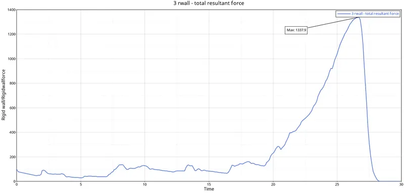
The maximum force experienced by the rigid wall was found to be 1337.9KN.
Case 3 : Create the type 11 contact and run.
Here a type 11 contact was given.This interface simulates impact between edge to Edge or lines. A line can be a beam or truss element or a shell edge or spring elements. In association with interface TYPE7, interface TYPE11 solves the locking cases
• Defined by identifying master and slave lines (edges)
• Impacts occur between a master and a slave line. A slave line can impact on one or more master lines. A line can belong to the master and the slave side. This allows self-impact.
• Works similar to Type 7 in terms of Penalty formulation, Gap definition and search method.
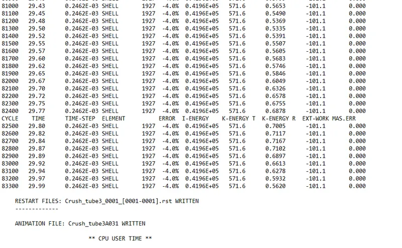
Here the mass error was found to be little more compared to case 1 and case 2.
Energy plot
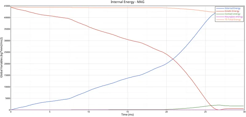
From the plot its seen that the kinetic energy is increasing and when the crash happens it declines and dips. In the same time a increase in the value of internal energy was observed in which kinetic energy is been converted to internal energy. The total energy remails constat for some time and the curves dips at the end Also there was slight increase in hourglass and contact energy were been observed.
Rigid wall force
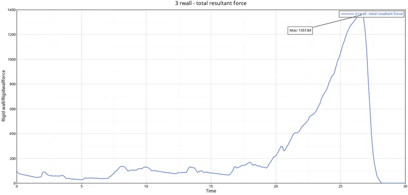
The maximum rigid wall force was found to be 1357.64KN.
Case 4
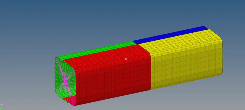
In case 4 the notches were removed using the align tool and the boundary conition assigned to the rigid elements were deleted.
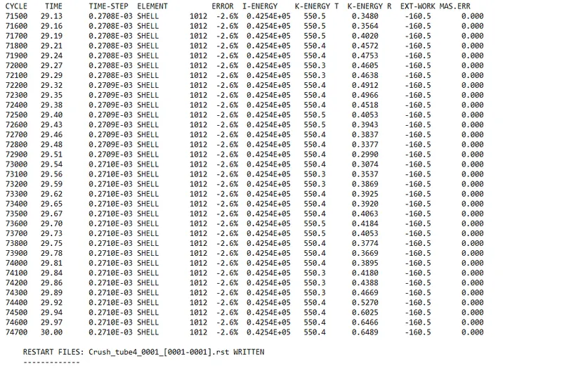
The energy error was found to be minimum compared to the other cases.
Energy plot
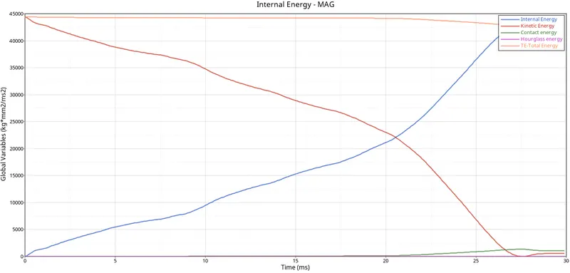
From the plot its seen that the kinetic energy is increasing and when the crash happens it declines and dips. In the same time a increase in the value of internal energy was observed in which kinetic energy is been converted to internal energy. The total energy remails constat for some time and the curves dips at the end Also there was slight increase in hourglass and contact energy were been observed.
Rigid wall force
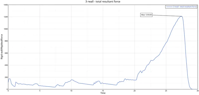
The maximum rigid wall force was found to be 1210.93KN.
Case 5
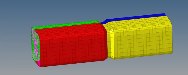
In case 5 a new notch was given in the middle and ran the simulation.
The energy
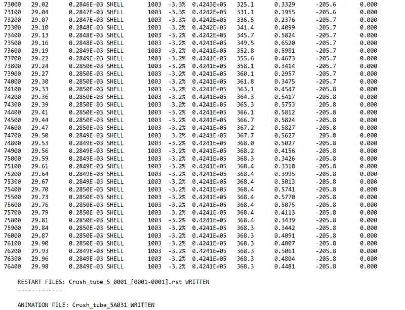
The energy error was found to be -3.2%.
Energy plot
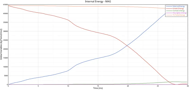
From the plot its seen that the kinetic energy is increasing and when the crash happens it declines and dips. In the same time a increase in the value of internal energy was observed in which kinetic energy is been converted to internal energy. The total energy remails constat for some time and the curves dips at the end Also there was slight increase in hourglass and contact energy were been observed.
Rigid wall force
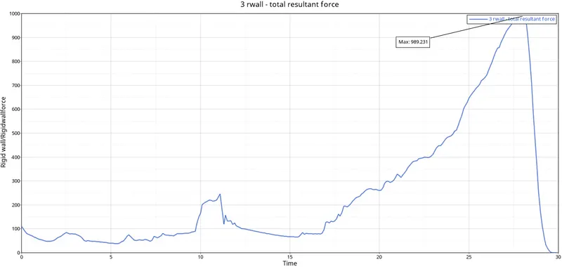
The maximum rigid wall wall force was found to be 989.2 KN.
Case 6
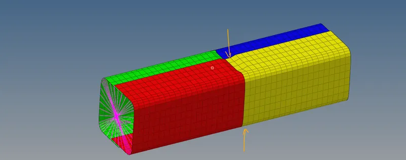
In case 6 new notches were formed on the opposite faces as shown below.
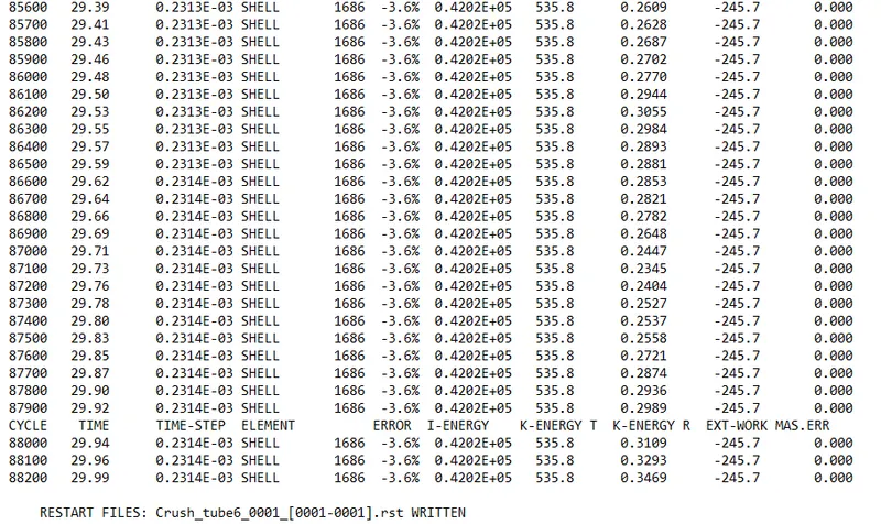
The energy error was found to be -3.6%.
Energy plot
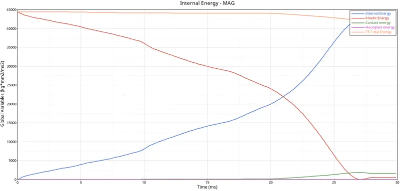
From the plot its seen that the kinetic energy is increasing and when the crash happens it declines and dips. In the same time a increase in the value of internal energy was observed in which kinetic energy is been converted to internal energy. The total energy remails constat for some time and the curves dips at the end Also there was slight increase in hourglass and contact energy were been observed.
Rigid wall force
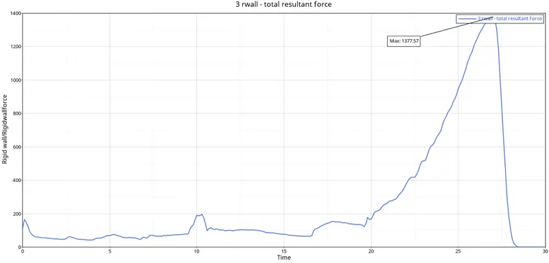
The maximum value for the rigid wall force was found to be 1377.57 KN.
Conclusion
The simulation was performed as per the conditions given in the question and noted down all the rigid wall forces, energy plot and mass errors. Since when notches were introduced those region become a critical part of the structure and we would find more stress distribution over those regions. Here we have used two type of contacts to get to know the deviation in results. When compared the energy error was found to be very less in the case 5.
___________________
File: https://drive.google.com/drive/folders/1Vr1-46-utuV2Cr7c2aItohGAIZvAkpkz?usp=sharing