Assignment 5-RADIOSS Interfaces & Study of Effect of Notches Challenge
Aim: To study interfaces and study the effect of notches challenges.
Objective: Create the mesh for bumper assembly,mesh size should be 6mm.
- Run the crash tube model as it is.
- Change the Inacti=6 and run.
- Create the type 11 contact and run.
- Remove both notches and remove boundary condition on rigid body node then run.
- Create a new notch in the middle ,select the whole section and run.
- Create a new notch with nodes only from opposing 2 faces and run.
Note:
- Plot RWALL forces ,contact forces,internal energy and Create TH/PART for all parts and compare results for all cases.
- Comment your thought on why there is a change in the internal energies.
- How does the notch affect the results?
- Plot energies and note any difference.
Information:
What does Interface mean?
The interface means how the elements behave with each other when they are in contact. The explicit analysis method efficiently solves complex dynamic contact problems (boundary condition nonlinearity). Accurate modeling of contact interfaces is essential to correctly capture contact interaction between bodies. RADIOSS has a large number of contact types suitable for many applications. In RADIOSS an interface is created by defining the master segment and slave node-set. The master segment can be parts of components, elements, contact surface, node surface sets, and slave entities that can be parts of components and node sets. The contact algorithm will check every time step for potential penetration of a slave node through a master segment. If penetration is detected the contact is treated with either a Penalty or Lagrange multiplier method.
Type7: Interface TYPE7 is a multi-usage impact interface, modeling contact between a main surface and a group of secondary nodes. It is also possible to consider heat transfer and heat friction.
The limitations that were encountered with interfaces TYPE3, TYPE4 and TYPE5 are solved with this interface: A node can at the same time be a secondary and a main node. Each secondary node can impact each main segment; except if it is connected to this segment. A node can impact on more than one segment. A node can impact on the two sides, on the edges and on the corners of each segments. It is a fast search algorithm without limitations.
The main limitations of this interface are: Time step is reduced in case of high impact speed or contacts with small gap. It does not work properly if used with a rigid body at high impact speed or rigid body with small gap. It does not solve edge to edge contact (to solve this, /INTER/TYPE11 should be used along with TYPE7).
Type11: This interface simulates impact between edge to Edge or lines. A line can be a beam or truss element or a shell edge or spring elements. The interface properties are: Impacts occur between a main and a secondary line. A secondary line can impact on one or more main lines. A line can belong to the main and the secondary side. This allows self-impact. This interface can be used in addition to /INTER/TYPE7 to solve the edge to edge limitation of interface TYPE7.
Procedure:
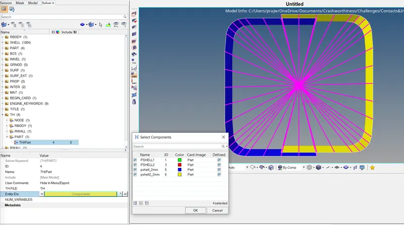
NOTE: For all the cases import the given .rad files using import solver deck; after importing create TH/PART for the 4 components for obtaining the results on them as shown below; and run the analysis using analysis > radioss > saveas > radioss.

_____________________________________________________________________________________________________
- Following was performed for the cases mentioned below
Case1:
Running analysis for the given model.
Case2:
Changing the Inacti=6.
From: 0/default TO: 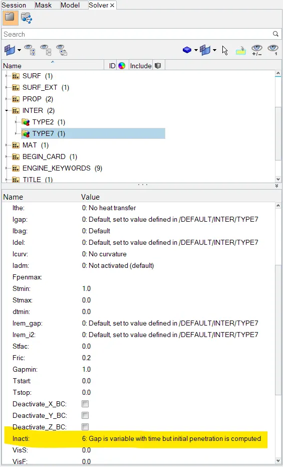
Case3:
Creating a new type 11 contact and assigning lineID for slave and master for for the following components as shown:
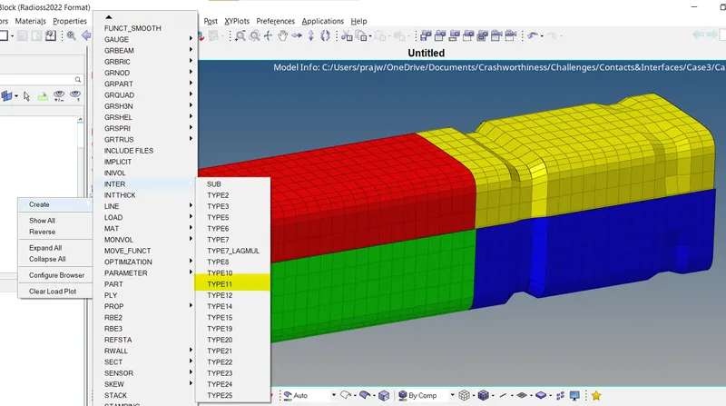
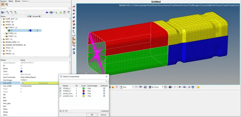
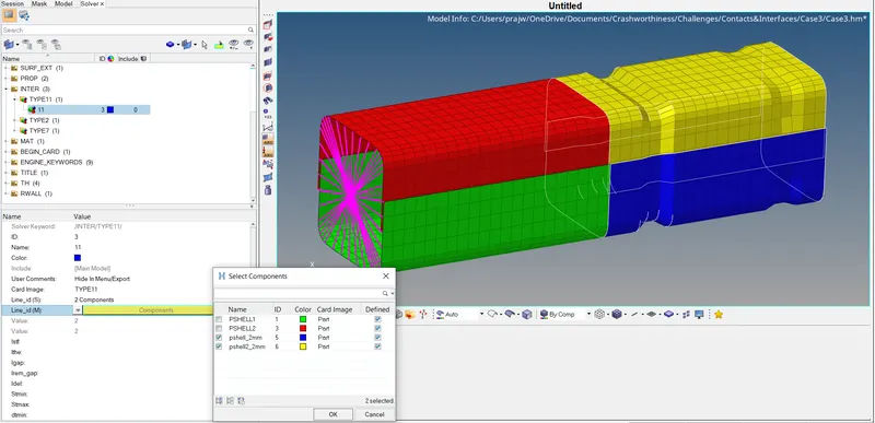
Case4:
Deleting/removing the boundary conditions. And also removing the notches present by using align node option(F7).
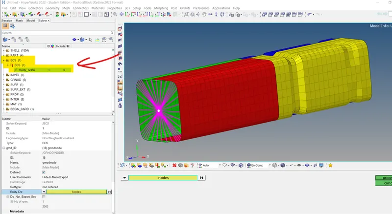
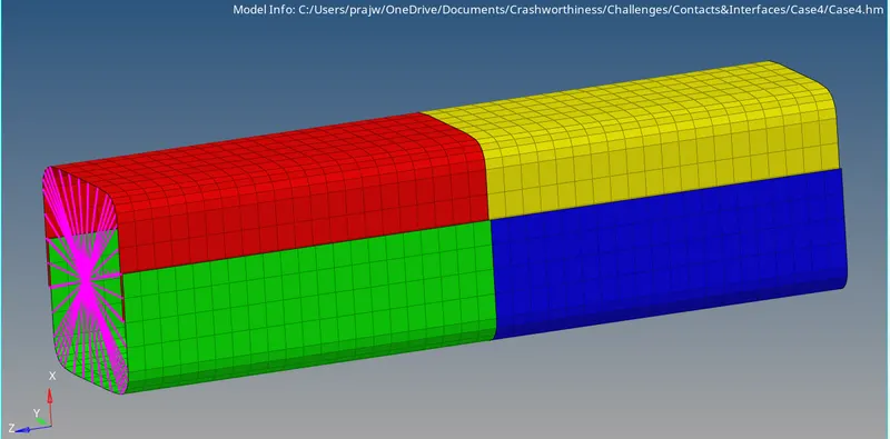
Case5:
Removing the pre existing notches and creating a notch in the middle throughout the component as shown below.
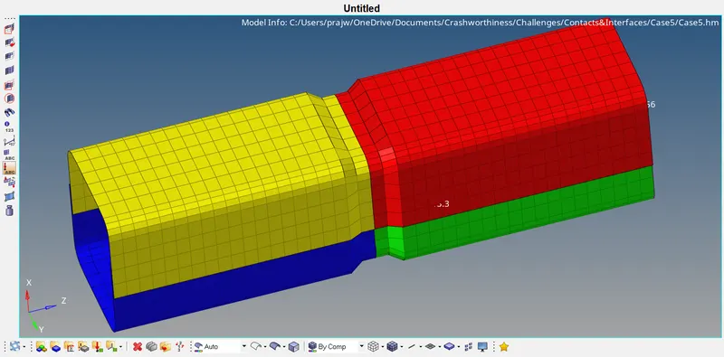
Case6:
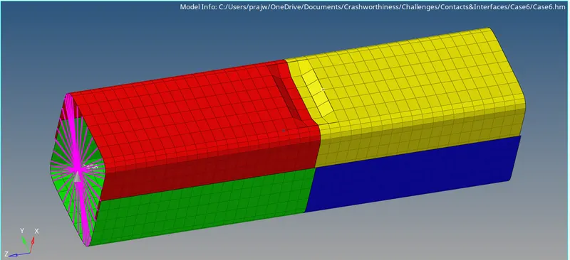
Removing the pre existing notches and creating a notch on the opposite faces in the middle as shown below.
_____________________________________________________________________________________________________
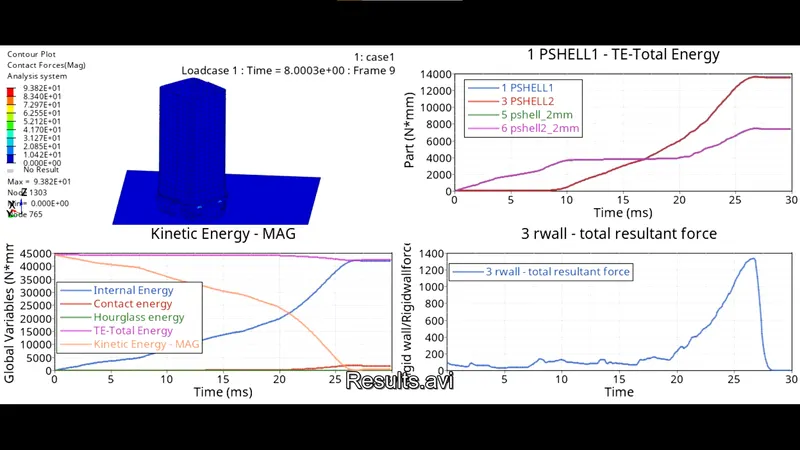
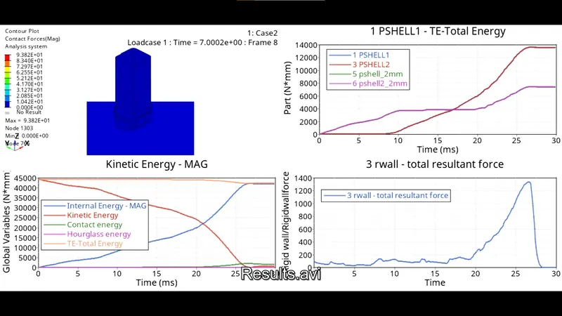
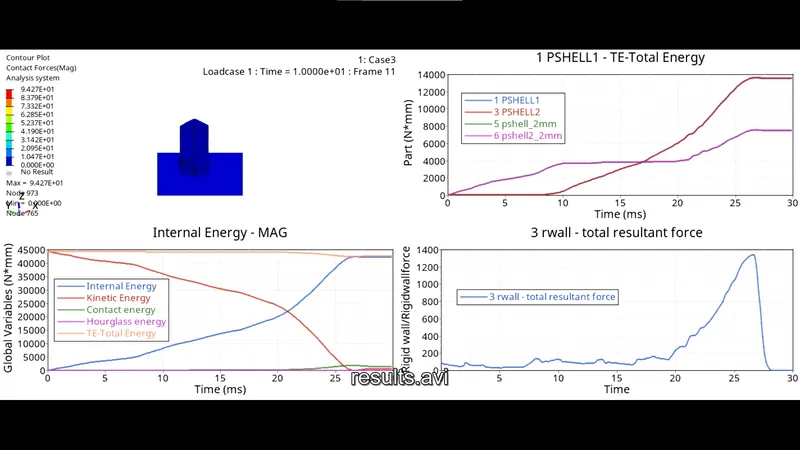
- After running the analysis, divide the graphics window into 4 parts and plot RWALL forces, contact forces, internal energy and part forces.
Case1:
Case2:
Case3:
Case4:
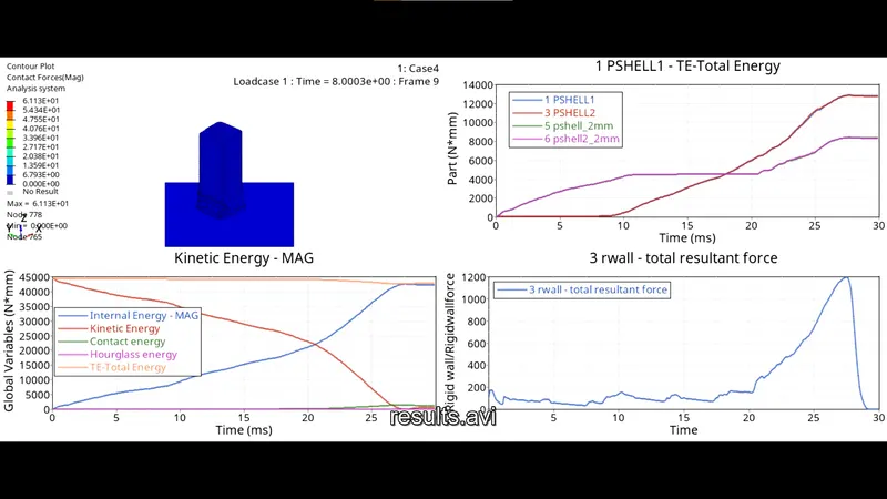
Case5:
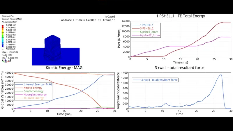
Case6:
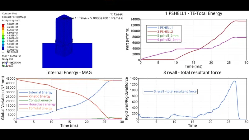
_____________________________________________________________________________________________________
For Case 1: Checkout for 0001.out for the results

Similarily after checking for all the results and output files we get the following results mentioned:
OBSERVATION & CONCLUSION:
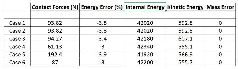
In all the cases the hourglass energy is below the internal energy. The energy error is also within the acceptable range. In case 4 since the notch is removed, the stress induced in the crush tube is the least compared to other cases. The areas on the crush tube which have notches on it act as stress concentrated and these areas tend to crush. The deformations are predictable in case of notched components. In case 1 where Inacti = 0 there is no initial penetration. Energy error for all cases is between -3% to -4% which is acceptable.