Assignment 5
Aim:
The main aim is to create a mesh, give connections, and to simulate the given models.
Objective:
The objective for this project is as below.
For Model 1:
- To create the mesh for bumper assembly, the Target element size should be 6mm.
For Model 2:
- For Model 2, to simulate the crash tube model as it is.
- Change the value of Inacti to 6 and run the simulation.
- Create the type 11 contact and simulate it.
- Remove both the notches in the model and remove boundary condition on rigid body node and run the simulation
- Create a new notch in the middle and run the simulation.
- Create a new notch with nodes only from opposing 2 faces and run the simulation.
Tasks to Complete:
- Plot RWALL forces, contact forces, internal energy graph, and Create TH/PART for all parts and compare results for all cases.
- why there is a change in the internal energies?
- How does the notch affect the results?
- Plot the energies and explain if any differences occurred.
Methodology:
For Model 1:
- Opening the file.
- Giving the Criteria.
- Performing the Mesh.
- Giving the Spot weld connection.
For Model 2:
- Opening the File.
- Studying the Cases.
- Comparing the Cases.
Theory:
Interfaces:
Interfaces are defined to model how the parts interact when they come into contact with each other.
In Interfaces, there are four types to look at
- Penalty Method.
- Type 7 Method.
- Type 11 Method.
- Type 24 Method.
- Penalty Method:
- The Penalty method treats the behavior between slave nodes and master segments as springs that generate resistive forces as a function of penetration.
- The Spring Elements are created between the Slave node and its projection. The spring stiffness is automatically computed according to the material and property of both the master segment and slave node.
Bumper:
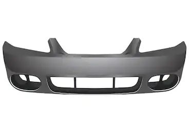
A bumper is a structure attached to or integrated with the front and rear ends of a motor vehicle, to absorb impact in a minor collision, ideally minimizing repair costs. Stiff metal bumpers appeared on automobiles as early as 1904 that had a mainly ornamental function. Numerous developments, improvements in materials and technologies, as well as greater focus on functionality for protecting vehicle components and improving safety have changed bumpers over the years. Bumpers ideally minimize height mismatches between vehicles and protect pedestrians from injury. Regulatory measures have been enacted to reduce vehicle repair costs and, more recently, impact on pedestrians.
Procedure:
For Model 1:
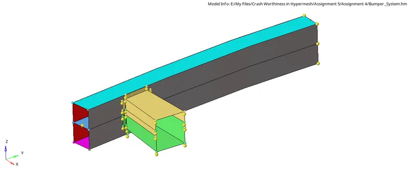
- Opening the File:
- To Open the .hm file, Go to the File menu in the Standard menu bar >> Click Open >> Click Model >> Select the model to open >> click
- The model is displayed in the Graphics Area.
- Giving the Criteria:
- To give the Criteria, Click on the Preferences in the Standard Menu bar >> Click Criteria Menu Settings >> Give Target Element Length as 6mm >> Click Ok.
- The Criteria are given.
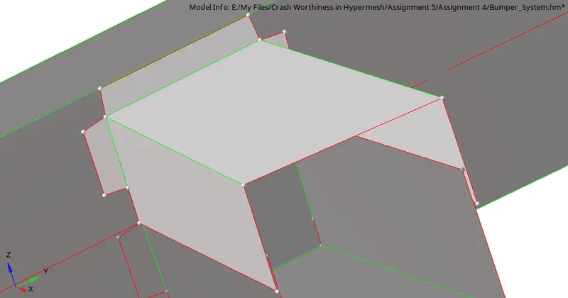
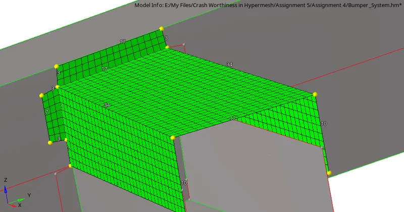
- Performing the Mesh:
- To perform a mesh, Select Auto mesh option from the 2D panel >> Click the Surface to mesh >> Give the Element size as 6 >> Click mesh.
- The Mesh is completed and the model is made sure that there are no tria elements in the model.


- Giving the Spot weld connection:
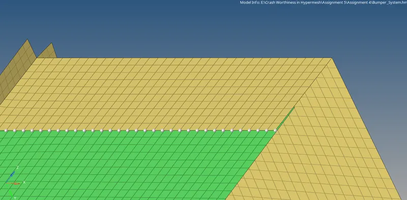
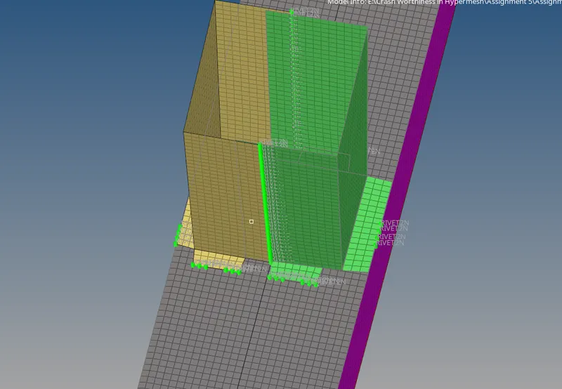
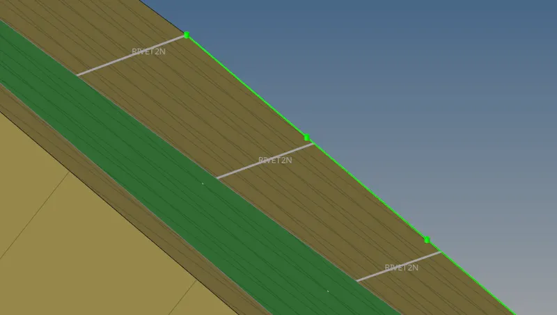
- The connections for the spot weld can be selected from the 1D >> Select connectors tool >> Select Spot option >> Select the Location as Node list >> Select the Nodes >> Give the Spacing as 6 >> Select the comps in the “Connect what” area >> Give the Tolerance as 6 >> Give the Type as Weld >> Click Create.
- The Connections are given at different locations where the 2 surfaces are placed parallel to each near and therefore, a connection can be made.



For Model 2:
- Opening the Cases:
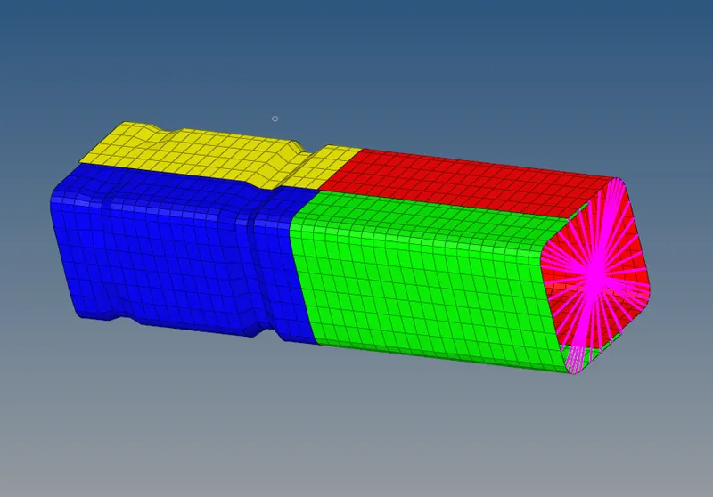
- To open the .rad file, Go to the Import section in the Standard tool bar >> Select Import from Solver Deck >> Select the File to import (File Name: Crush_tube_0000.rad) >> Click Import.
- The Model is imported.
- Studying the Cases:
- Case 1:
- After the Model is imported, The Simulation needs to be performed in this case.
- To simulate the model, Go to the Analysis Panel, Select the Radioss Option >> Select the area to save the file (Note: Save the File in separate folder naming Case 1 as it will be easy to check the models) >> Check include collectors box >> In the options tab, type “-nt 4” >> Click Radioss.

- The Simulation is run without errors.
- Case 2:
- In this case, the Inacti value should be changed.
- To change the value, go to the model browser in the Tab Area >> Click Group tab >> Select Self Contact Option >> In the Edit Entity bar, the Inacti value is displayed as 0. >> Change the Inacti value to 6.
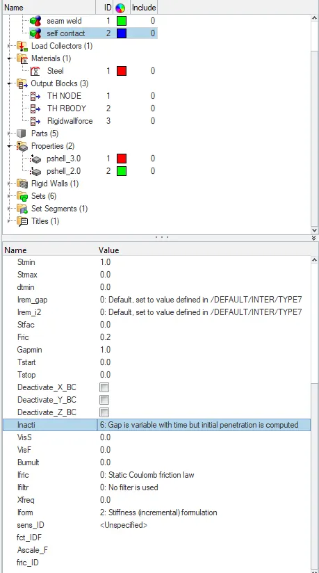
- To simulate the model, Go to the Analysis Panel, Select the Radioss Option >> Select the area to save the file (Note: Save the File in separate folder naming Case 2 as it will be easy to check the models) >> Check include collectors box >> In the options tab, type “-nt 4” >> Click Radioss.
- Case 3:
- To create a New Type interface, Right-click on the Groups tab in the Model Browser >> Name the New group as “Type 11” >> Give the Values of Istf (Flag for Stiffness Definition) to 4, Igap (Flag Gap/ Element option) to 1000, Idel (Flag for node and segment deletion) to 0, Stmin (Minimum Stiffness) to 1, Stmax (Maximum Stiffness) to 0, Iform ( Flag for Stiffness or Viscous Formulation) to 0, Fric (Coulomb Friction) to 0.25, Gapmin (Gap for impact activation) to 0.45, Inacti (Flag for deactivation of stiffness) to 6. >> Click on the screen
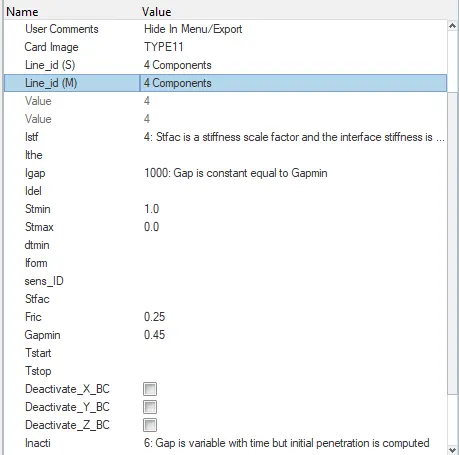
- The new interface card is prepared.
- To simulate the model, Go to the Analysis Panel, Select the Radioss Option >> Select the area to save the file (Note: Save the File in separate folder naming Case 3 as it will be easy to check the models) >> Check include collectors box >> In the options tab, type “-nt 4” >> Click Radioss.
- Case 4:
- In this case, the notch needs to be deleted and make it into a plane mesh.
- To delete the Notch, Click F2 on the keyboard or Go to the Tools panel and select Delete option >> Select the Elements to delete >> Click on delete Entity.
- The Notch elements are deleted.
- To create a plane surface, Go to the 2D panel, Select Ruled option >> Select the first Node list (one end of the part which is needed to be created) >> Select the Second Node List (another end of the model which is needed to create connectivity) >> Click Create. >> The mesh is created Give the element length as 6 >> Click Recalculate >> Click mesh.
- The mesh is created properly.
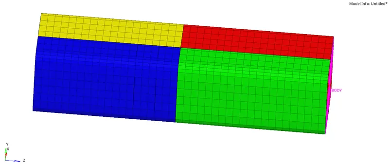
- Now to delete the Boundary conditions, Go to the Solver Deck, If the Solver deck is not visible, Go to the View tab in the Standard menu bar>> Click Browse >>Click Hyper Mesh >> Click on Solver >> The Solver Deck will be opened. >> Delete the BCS Entity in the Solver Deck.
- The Boundary condition entity is deleted.
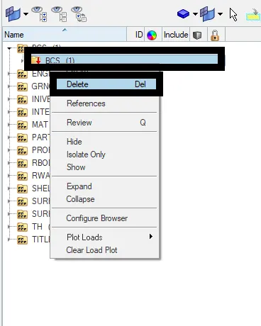
- To simulate the model, Go to the Analysis Panel, Select the Radioss Option >> Select the area to save the file (Note: Save the File in separate folder naming Case 4 as it will be easy to check the models) >> Check include collectors box >> In the options tab, type “-nt 4” >> Click Radioss.
- The Simulation is run successfully.
- Case 5:
- In this case, a new notch needs to be created and to create a notch in the plane surface, the Translate option is used.
- To Translate the elements, Go to the Tools panel, Select Translate option >> Select the Nodes to translate >> Select the Orientation of the elements (i.e. in which direction the elements should be moved) >> Give the Magnitude as 4.094 (Distance from node to node).

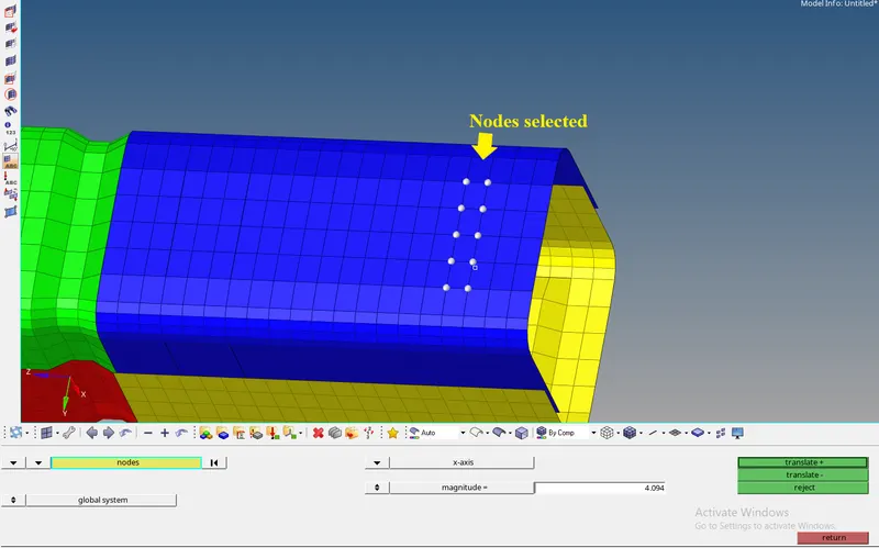
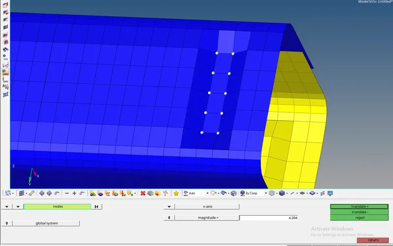
- The Notch is created.
- To simulate the model, Go to the Analysis Panel, Select the Radioss Option >> Select the area to save the file (Note: Save the File in separate folder naming Case 5 as it will be easy to check the models) >> Check include collectors box >> In the options tab, type “-nt 4” >> Click Radioss.
- The Simulation is run successfully.
- Case 6:
- In this case, a notch should be created at the same place in the opposite direction.
- Again to create a notch, the Translate option is used.
- Go to the Tools panel, Select Translate option >> Select the Nodes to translate >> Select the Orientation of the elements (i.e. in which direction the elements should be moved) >> Give the Magnitude as 4.094 (Distance from node to node).
- The Notch is created.
- To simulate the model, Go to the Analysis Panel, Select the Radioss Option >> Select the area to save the file (Note: Save the File in separate folder naming Case 5 as it will be easy to check the models) >> Check include collectors box >> In the options tab, type “-nt 4” >> Click Radioss.
- The Simulation is run successfully.
- Animations for the Cases:
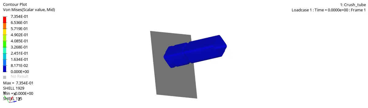
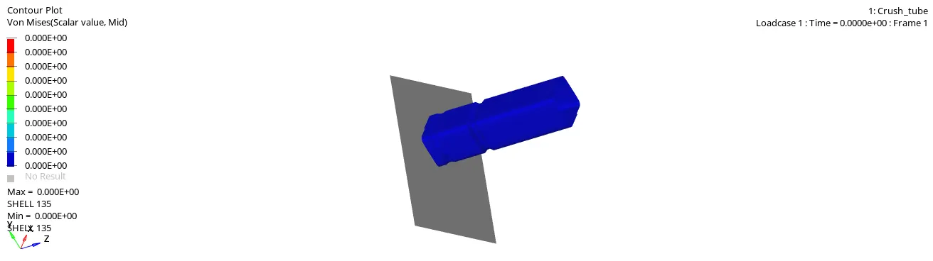
- To create an animation, Go to the Hyper View in the Client Selector. >> Hyper view is opened>> Select the File to view the animation (Note: File is in .h3d format in the respective case folder) >> Click Apply.
- Case 1:
- Case 2:
- Case 3:
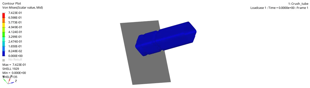
- Case 4:
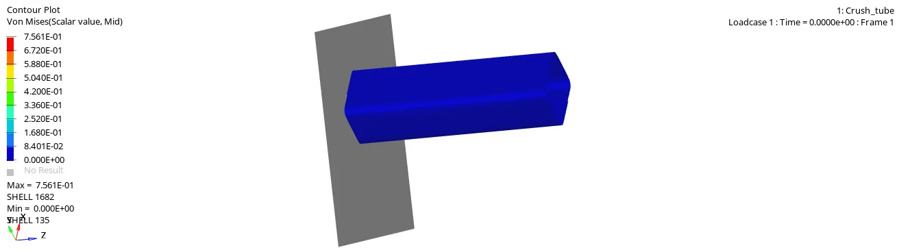
- Case 5:
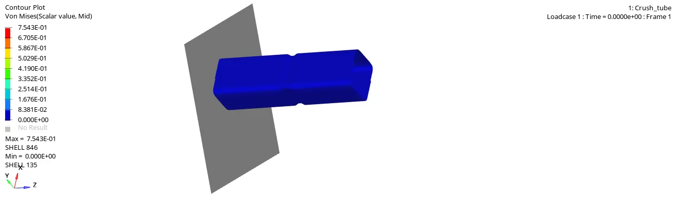
- Case 6:
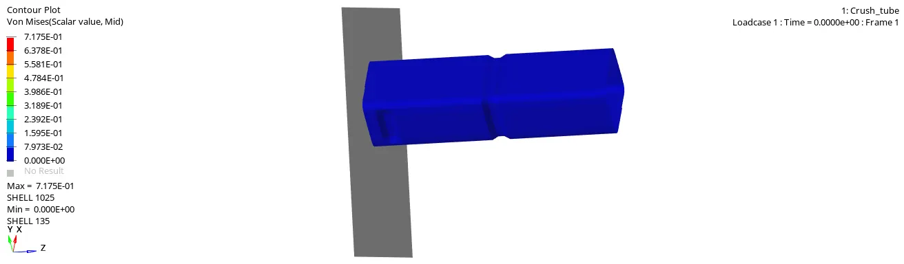
- The animation is opened and it can be seen by clicking play in the Toolbar.
- Plotting the Graphs for the Cases:
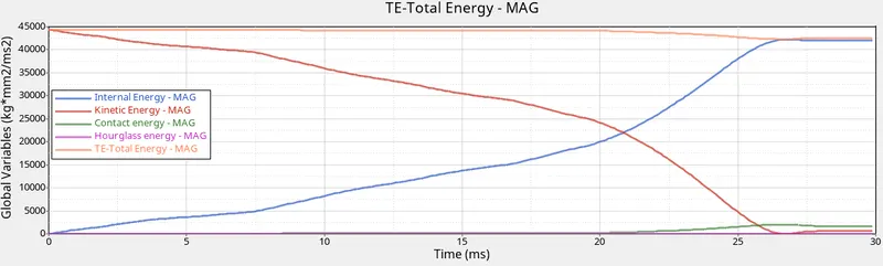
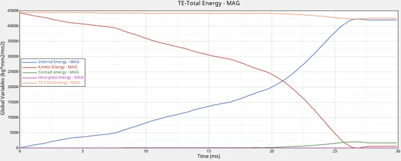
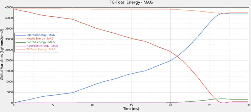
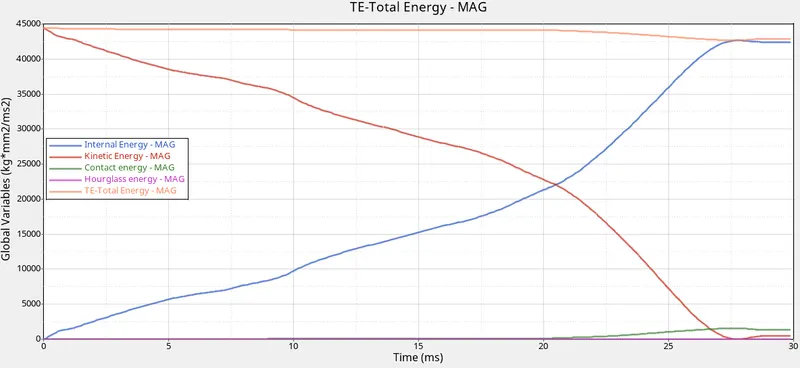
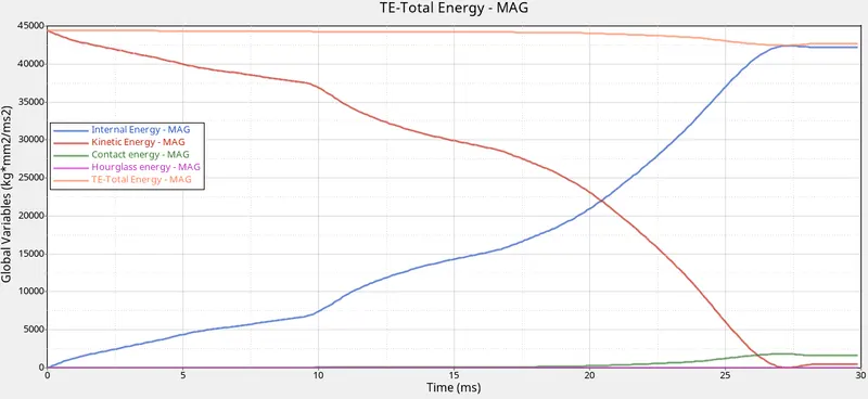
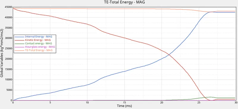
- To plot the graph, go to the Client Selector option in the Tool Bar >> Change it to HyperGraph 2D >> The HyperGraph is opened >> Select the Data File from the respective folder >> Select Global Variable > Internal Energy, Kinetic Energy, Total Energy, Hourglass Energy, Contact Energy > MAG >> Click Apply.
- The method is the same for the other cases.
- Case 1:
- Case 2:
- Case 3:
- Case 4:
- Case 5:
- Case 6:
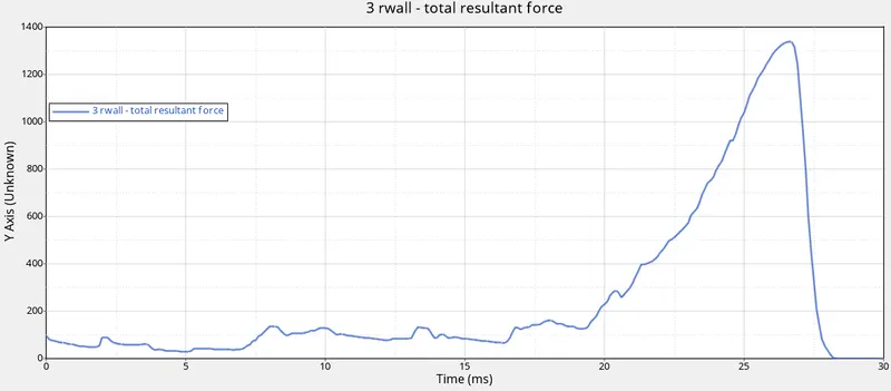
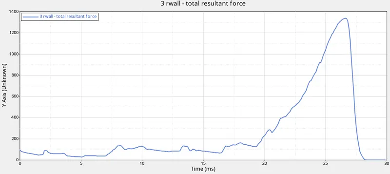
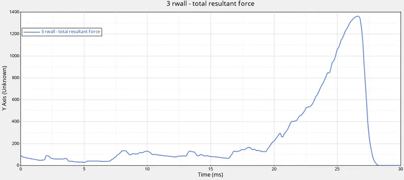
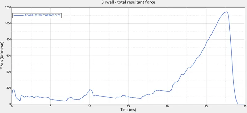
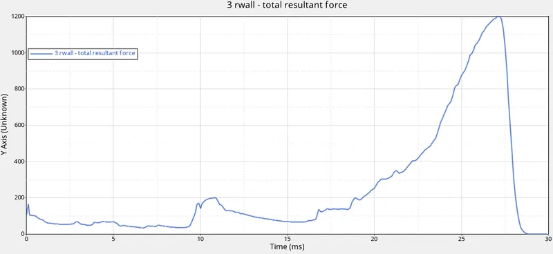
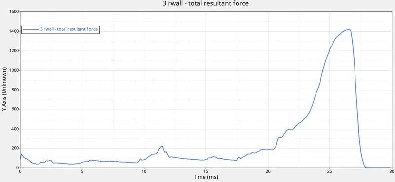
- For the Rigid Wall Forces, Click Rigid wall/ Rigid Wall force >> Click 3 rwall >> Click Total Resultant force >> Click apply.
- Case 1:
- Case 2:
- Case 3:
- Case 4:
- Case 5:
- Case 6:
- The Plots are created.
- Observing the Cases:
- Upon observing all the cases it can be seen that the area near the notch will deform first and then the plane surface gets deformed.
- It can be noted that the notch plays an important role in the deformation of the Tube.
Result:
For Model 1, the mesh is generated and the connections were given to the model.
For Model 2, the cases are simulated with the given tasks completed.
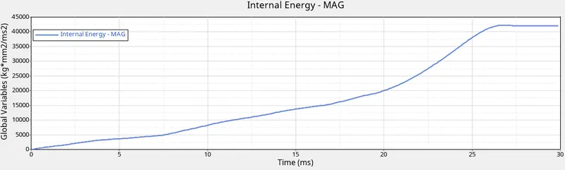
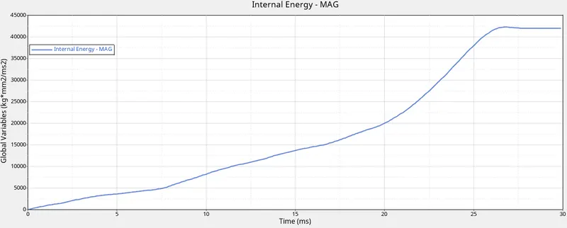
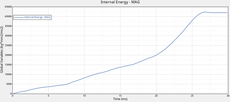
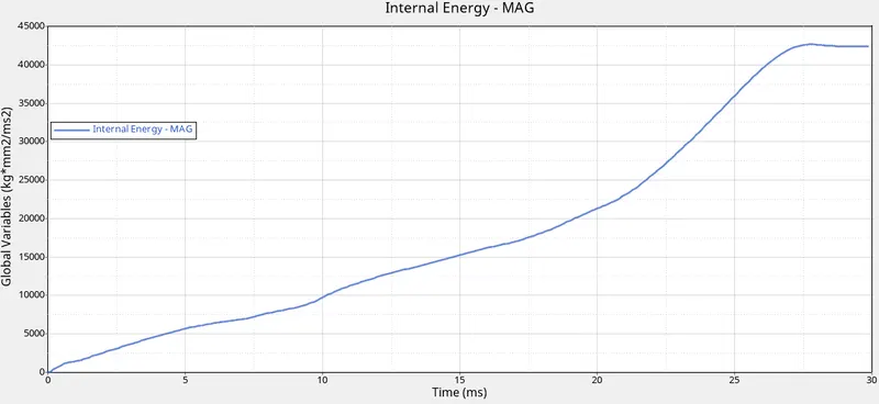
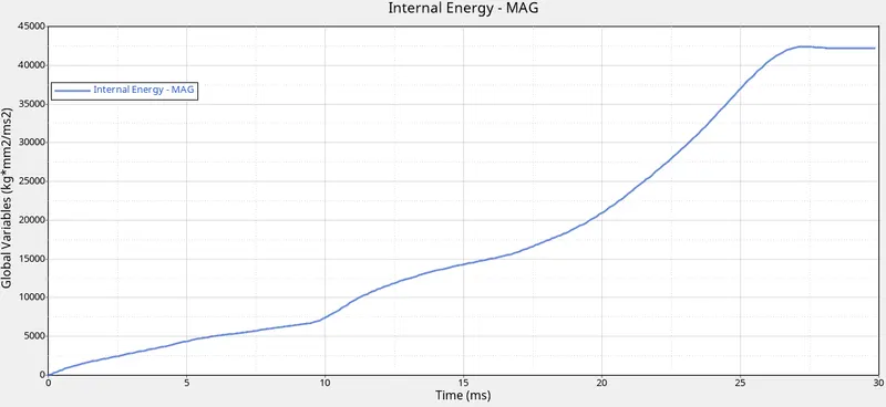
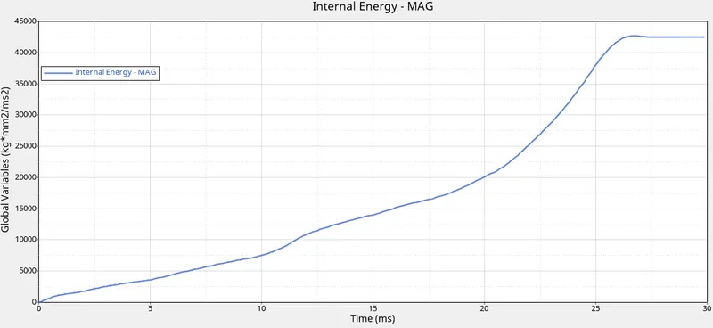
Why there is a change in the internal energies?
The change in the internal energy is due to the notch. With the removal of the notch, the internal energy decreases and hence reduces the energy error as well.
Case 1:
Case 2:
Case 3:
Case 4:
Case 5:
Case 6:
How does the notch affect the results?
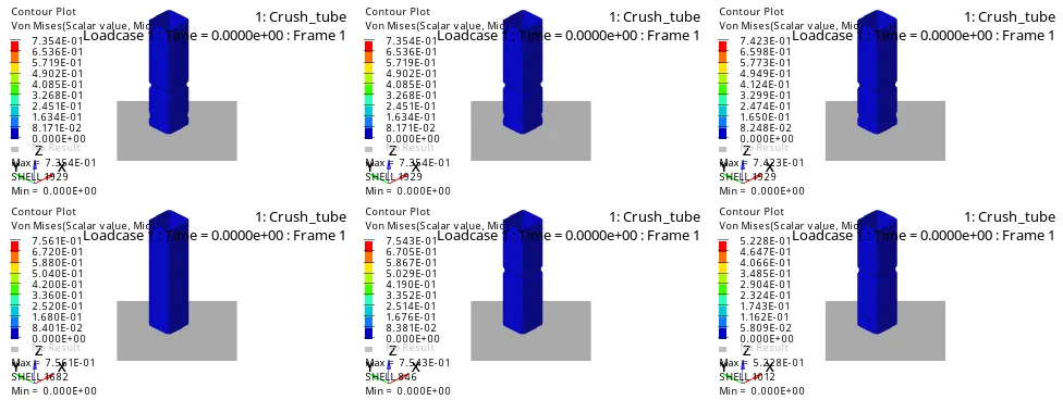
The notch areas have high stresses and deform first. In the plane surface where the notches are removed the stress levels are low. Hence, we can state that by removing the notch helps to reduce the stress acting in the body.
Terms Used:
Type 7:
- Type 7 is a Node to surface type of contact.
- A general-purpose interface and can simulate all types of impact between a set of nodes and a master surface.
- It is a Non-Oriented and Slave nodes can belong to the master surface and hence, auto impact possible.
- Automatic Nodes to surface contact interface using the penalty method with variable stiffness.
Type 11:
- The Type 11 will be an Edge to Edge type of contact.
- In the case of edges crossing, the Type 11 interface can be added to capture the physics correctly.
- It is defined by identifying master and slave lines/edges.
- It works similarly in terms of Type 7 in terms of
- Penalty Formation.
- Gap Definition.
- Search method.
Istf:
It is a Gap for stiffness definition; it is the Interface stiffness which is the maximum of the master and slave stiffness.
Igap:
It is a gap/element option flag. The gap between the master and slave node is not defined in this case.
Idel:
It is the Node and segment deletion flag. The value is set to 0. It is defined as the default values added in the /DEFAULT/INTER/TYPE11
Stmin:
It is the minimum stiffness value and can be used only if the Istf is not equal to 1.
Stmax:
It is the maximum stiffness value and can be used only if the Istf is not equal to 1.
The Default value is `10^30`.
Iform:
It is the Friction penalty formulation type. In this case, it is set to 0 which takes the value defined in the /DEFAULT/INTER/TYPE11.
Fric:
It is a Coulomb Friction and it refers to a simple model of dry friction that is fairly accurate empirically. Specifically, it is a model that helps predict the direction and magnitude of the friction force between two bodies with dry surfaces in contact.
Gapmin:
It is the minimum gap for the impact to activate.
Inacti:
It is the option to deactivate the stiffness. In this case, the Gap is variable with time, but initial penetration is computed as (the node is slightly de-penetrated)
`Gap_0=Gap- P_0-0.05(Gap-P_0)`
Where,
`P_0` = Initial Penetration of the Slave nodes.
`Gap_0` = Initial Gap between master segment and Slave nodes.
Learning Outcomes:
There are many this learned in this project.
- Learned what the flags inside the Groups mean and how they affect the model.
- Learned how the notch elements change the effect of the deformation.
- Learned to use the interfaces better.