CASE STUDY ABOUT TYPE2 , TYPE 7 AND TYPE 11 CONTACT INTERFACES AND THE INFLUENCE OF NOTCH IN THE CRUSH TUBE USING RADIOSS SOLVER.
OBJECTIVE:
- The main aim of this project is to study and compare the contact interface type 2, type 7, and type 11.
- To study how the notch influence the simulation in the crush tube model.
- To mesh the bumper assembly model with a 6mm element size.
BUMPER MESHING:
procedure followed:
- imported the given model (.hm) file into the Hypermesh GUI.
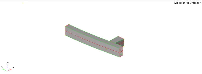
- checked for any geometrical failure in the model as shown below,
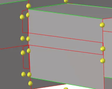
- cleared the topological failures using the tool: geometry-->quick edit (or) key fn+f11.
- Then the surface is meshed surface by surface using the tool:2D-->automesh panel with the mixed type and element size of 6mm.
- checked for the presence of back to back trias, opposite trias, rotational quads, edge trias and cleared by remeshing the elements.
- checked for the presence of free edges between the elements and cleared by increasing the tolerance value and replace option.
- Also created some surfaces using options like reflect, translate options.
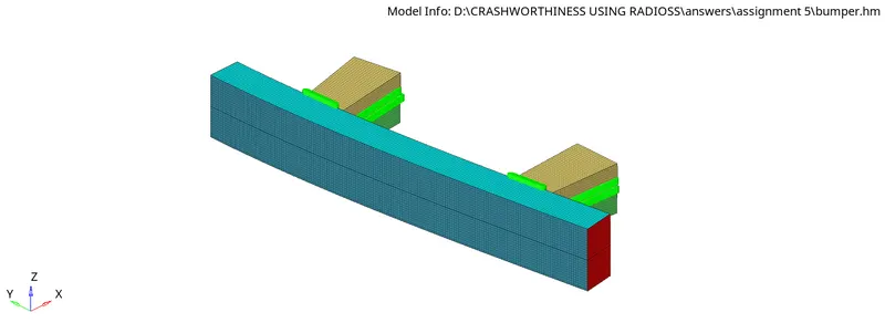
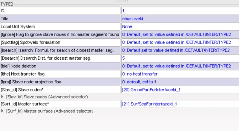
- connections are provided to the model, here seam weld type 2 is used to connect the assembly, as shown below,

model view:
CASE STUDY OF CONTACT INTERFACE TYPE 2, TYPE 7 AND TYPE 11 AND NOTCH APPLICATION:
CASE 1:
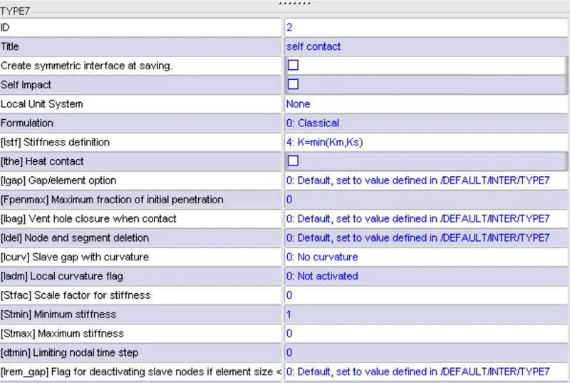
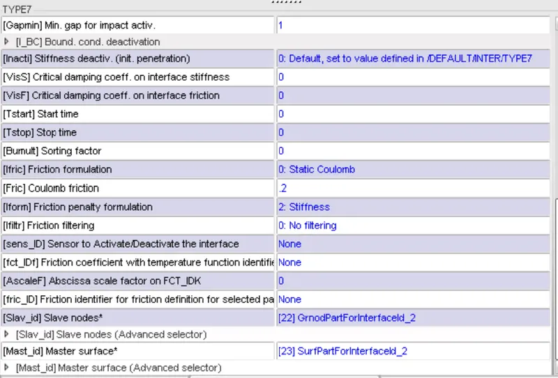
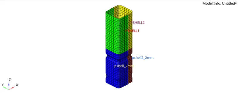
The simulation run is done using the Radioss solver with the contact interfaces type2 and type7 as shown below,
procedure:
- imported the given .rad file in the Hypermesh and simulation run is done with Radioss solver.
- imported the .h3d file and .T01 file in Hyperview and Hypergraph respectively.
- the animation for von mises stress, plastic strain, and displacement is observed and the graph for internal energy, contact energy, rigid wall forces are plotted.
observation:
- Here the buckling starts at the notch and then the down part and then the whole component gets impacted on the rigid wall.
-
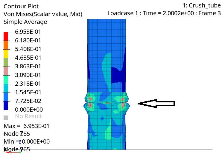
- Also, the element's edges intersect each other, when the whole component get impacted on the rigid wall, this is due to the absence of the type 11 contact interface.
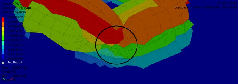
- the number of cycles at the end of the simulation is 83400 and the energy error is -3.8% and the mass error is 0.
In Hyperview:
plastic strain:
- the plastic strain starts at the middle notch edges and it develops all over the edges.
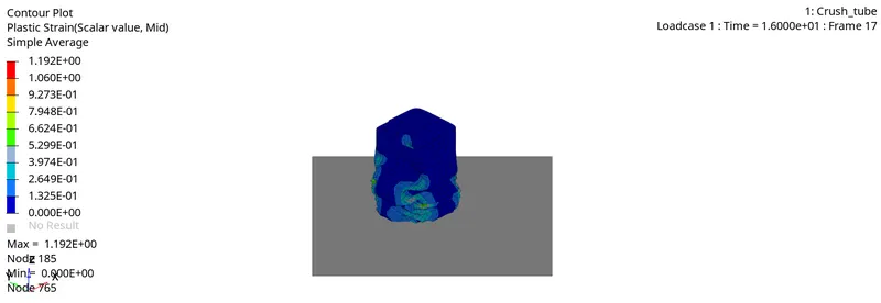
- here the maximum value is 1.192E+00 occurs at node 185.
von mises stress:
- the von mises stress starts at the middle notch.
- the von mises stress is the combination of all normal stresses and shear stress acts in each element, stress is the function of strain, if strain increases then the resistive force per unit area also increases so that less force is transmitted to the other end of load applied.
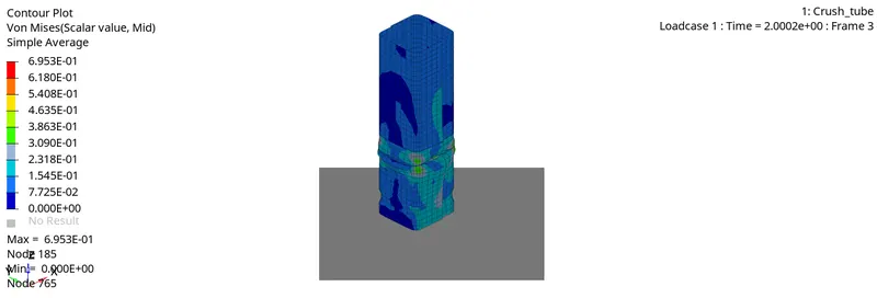
- here the maximum value is 6.953E-01 kN/mm^2 occurs at node 185.
Displacement:
- Here the displacement occurs maximum at the top of the crush tube in the direction of the force applied.
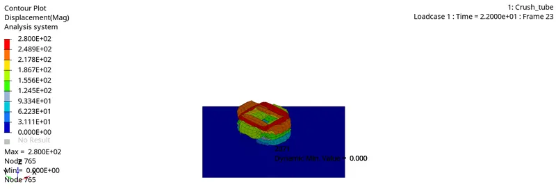
- Here the maximum value is 2.800E+02 mm occurs at node 765 and the minimum value 0 occurs at the same node.
In Hypergraph:
internal energy:
- whenever a body is strained some energy is absorbed in the body and the energy which is absorbed due to the straining effect is called strain energy or internal energy.
- the increase in the internal energy is approximately the same in Pshell 1 and Pshell_2 components having the same thickness of 3mm.
- Pshell_2mm and pshell 2_2mm components having 2 mm thickness also have the same level of increase in internal energy.
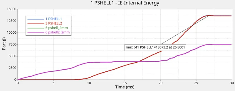
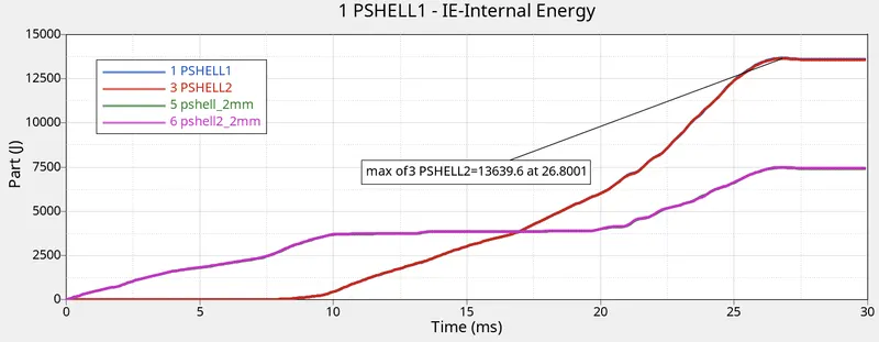
- the component with 3mm thickness has the maximum value of 13673.2 J and 13639.6 J at 26.8001 ms.
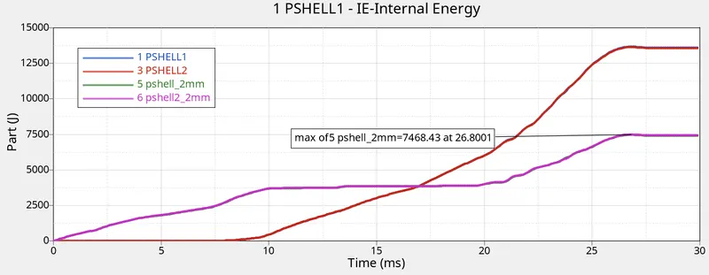
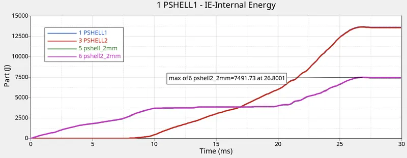
- the component with 2mm thickness has the maximum value of 7468.43 J and 7491.73 J at 26.8001 ms.
- from the I.E graph, the internal energy increases in P shell_2mm and Pshell2_2mm when the deformation below the middle notch occurs until the notch is impacted against the rigid wall, while internal energy in Pshell 1 and Pshell_2 remains constant, due to further deformation the internal energy in all parts reaches its maximum values as shown above.
contact energy:
- when two-component come in contact with each other, the interface force/ the resistive force is applied to the slave nodes in order to keep them outside the gap of the master surface elements. so the energy which is spent to avoid penetration is the contact energy.
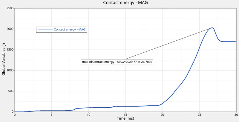
- the maximum value is 2029.77 J at 26.7002 ms.
rigid wall forces:
- the forces which are acting against the rigid wall are calculated here.
- the resultant normal force is the force that acts perpendicular to the rigid wall.
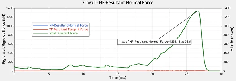
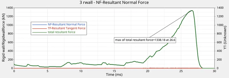
- it reaches its maximum value of 1338.18 KN at 26.6 ms.
- the tangent force is the force that acts parallel to the rigid wall eg: frictional forces, i,e. when the body is impacted completely on the rigid wall.
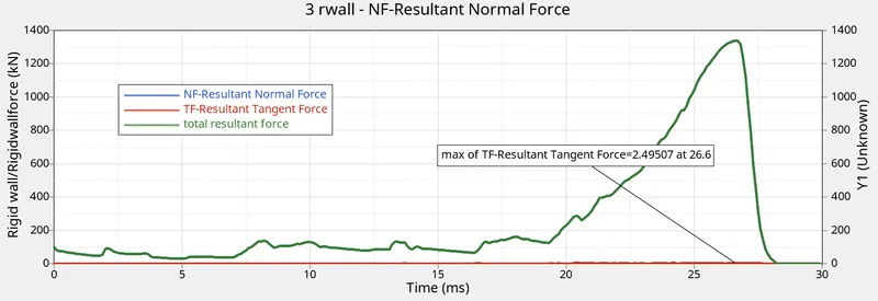
- the maximum value of the tangent force is 2.49507 KN at 26.6 ms.
- the total resultant forces trace the same path as the normal forces, reach its maximum value of 1338.18 KN at 26.6 ms.
CASE 2:
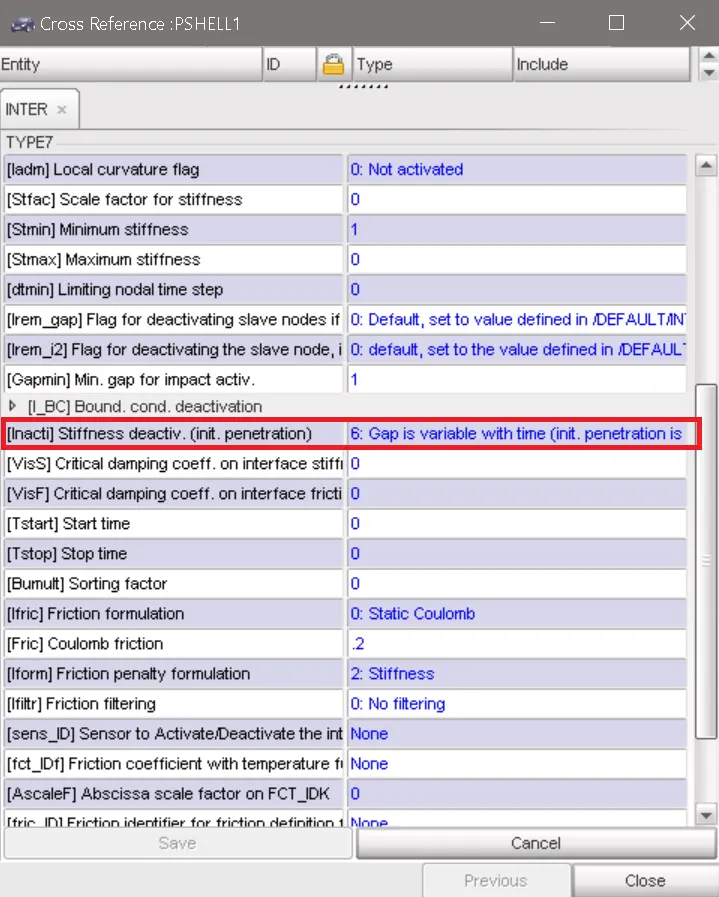
The simulation run is done using the Radioss solver with the contact interfaces type2 as the before the case and type7 with inacti=6 as shown below,
procedure:
- imported the given .rad file in the Hypermesh and simulation run is done with Radioss solver.
- imported the .h3d file and .T01 file in Hyperview and Hypergraph respectively.
- the animation for von mises stress, plastic strain, and displacement is observed and the graph for internal energy, contact energy, rigid wall forces are plotted.
observation:
- the number of cycles at the end of the simulation is 83400 and the energy error is -3.8% and the mass error is 0.
In Hyperview:
plastic strain:
- the plastic strain starts at the middle notch edges and it develops all over the edges.
- here the maximum value is 1.192E+00 occurs at node 185.
von mises stress:
- the von mises stress starts at the middle notch.
- the von mises stress is the combination of all normal stresses and shear stress acts in each element, stress is the function of strain, if strain increases then the resistive force per unit area also increases so that less force is transmitted to the other end of load applied.
- here the maximum value is 6.953E-01 kN/mm^2 occurs at node 185.
Displacement:
- Here the displacement occurs maximum at the top of the crush tube in the direction of the force applied.
- Here the maximum value is 2.800E+02 mm occurs at node 765 and the minimum value 0 occurs at the same node.
In Hypergraph:
internal energy:
- whenever a body is strained some energy is absorbed in the body and the energy which is absorbed due to the straining effect is called strain energy or internal energy.
- the increase in the internal energy is approximately the same in Pshell 1 and Pshell_2 components having the same thickness of 3mm.
- Pshell_2mm and pshell 2_2mm components having 2 mm thickness also have the same level of increase in internal energy.
- the component with 3mm thickness has the maximum value of 13673.2 J and 13639.6 J at 26.8001 ms.
- the component with 2mm thickness has the maximum value of 7468.43 J and 7491.73 J at 26.8001 ms.
- from the I.E graph, the internal energy increases in P shell_2mm and Pshell2_2mm when the deformation below the middle notch occurs until the notch is impacted against the rigid wall, while internal energy in Pshell 1 and Pshell_2 remains constant, due to further deformation the internal energy in all parts reaches its maximum values as shown above.
contact energy:
- when two-component come in contact with each other, the interface force/ the resistive force is applied to the slave nodes in order to keep them outside the gap of the master surface elements. so the energy which is spent to avoid penetration is the contact energy.
- the maximum value is 2029.77 J at 26.7002 ms.
rigid wall forces:
- the forces which are acting against the rigid wall are calculated here.
normal force:
- the resultant normal force is the force that acts perpendicular to the rigid wall.
- it reaches its maximum value of 1338.18 KN at 26.6 ms.
tangent force:
- the tangent force is the force that acts parallel to the rigid wall eg: frictional forces, i,e. when the body is impacted completely on the rigid wall.
- the maximum value of the tangent force is 2.49507 KN at 26.6 ms.
total resultant forces:
- the total resultant forces trace the same path as the normal forces, reach its maximum value of 1338.18 KN at 26.6 ms.
CASE 3:
The simulation run is done using the Radioss solver with the contact interface type11 as shown below,
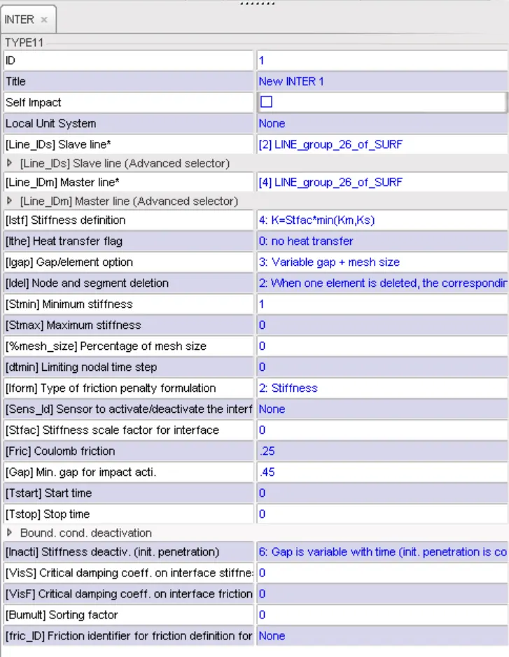
Here all 4 components are selected as master and slave.
procedure:
- imported the given .rad file in the Hypermesh and simulation run is done with Radioss solver.
- imported the .h3d file and .T01 file in Hyperview and Hypergraph respectively.
- the animation for von mises stress, plastic strain, and displacement is observed and the graph for internal energy, contact energy, rigid wall forces are plotted.
observation:
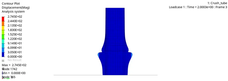
- Here without using the type 2 contact interface, the components get separated during the impact, also there are not element edges intersecting each other this is due to the usage of type 11 contact interface.
- the number of cycles at the end of the simulation is 99900 and the energy error is -5.9% and the mass error is 0.
In Hyperview:
plastic strain:
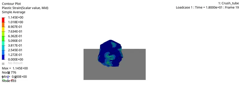
- here the maximum value is 1.145E+00 occurs at node 776.
von mises stress:
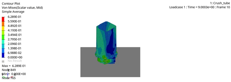
- here the maximum value is 6.289E-01 kN/mm^2 occurs at node 849.
Displacement:
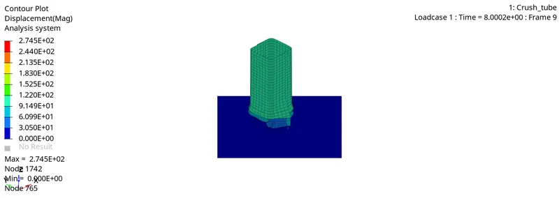
- Here the maximum value is 2.745E+02 mm occurs at node 1742.
In Hypergraph:
internal energy:
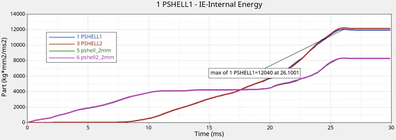
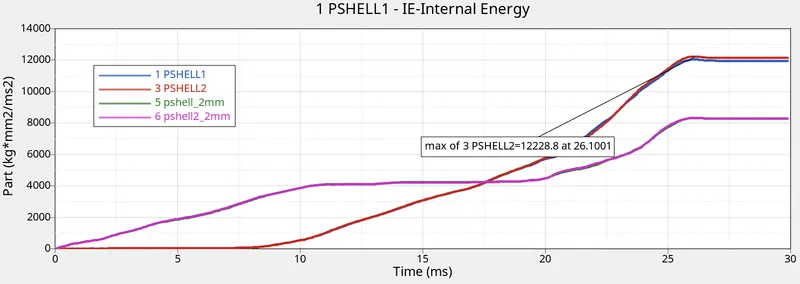
- the component with 3mm thickness has the maximum value of 12040 J at 26.1001 ms and 12228.8 J at 26.1001 ms.
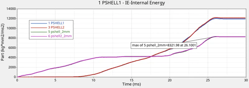
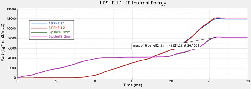
- the component with 2mm thickness has the maximum value of 8321.98 J at 26.1001 ms and 8321.23 J at 26.1001 ms.
contact energy:
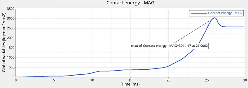
- the maximum value is 3044.47 J at 26.0002 ms.
- since the edge to edge contact interface produce interface forces when there is an edge to edge contact of the master and slave component.
rigid wall forces:
normal force:
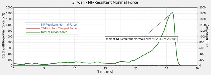
- it reaches its maximum value of 1823.66 KN at 25.9002 ms.
tangent force:
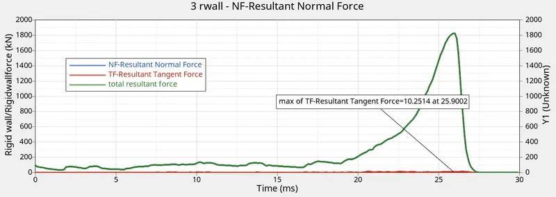
- the maximum value of the tangent force is 10.2514 KN at 25.9002 ms.
total resultant forces:
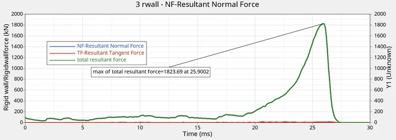
- the total resultant forces trace the same path as the normal forces, reach its maximum value of 1823.69 KN at 25.9002 ms.
CASE 4:
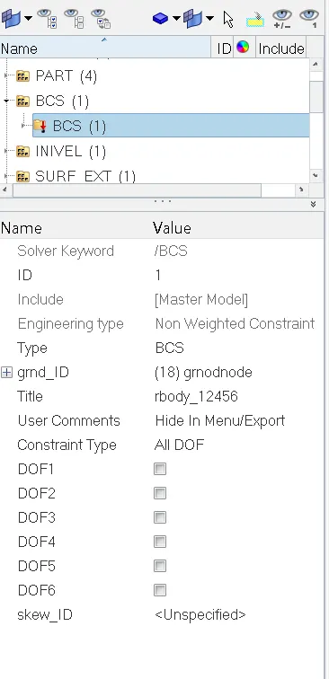
The simulation run is done using the Radioss solver with the contact interfaces type2 and type7 as shown in case 1 with no notch and no boundary condition applied to the Rigid body as shown below,
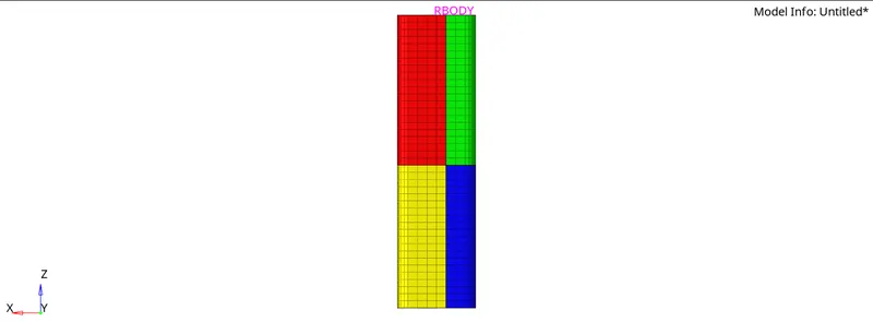
procedure:
- imported the given .rad file in the Hypermesh, using the (shift+f8) node edit-->align node option removed the notch.
- The simulation run is done with Radioss solver.
- imported the .h3d file and .T01 file in Hyperview and Hypergraph respectively.
- the animation for von mises stress, plastic strain, and displacement is observed and the graph for internal energy, contact energy, rigid wall forces are plotted.
observation:
- Here the deformation starts at the bottom of the component and then the whole body gets impacted against the rigid wall.
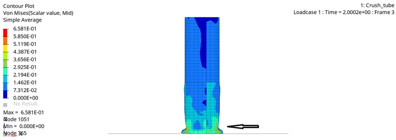
- the number of cycles at the end of the simulation is 77300 and the energy error is -2.9% and the mass error is 0.
In Hyperview:
plastic strain:
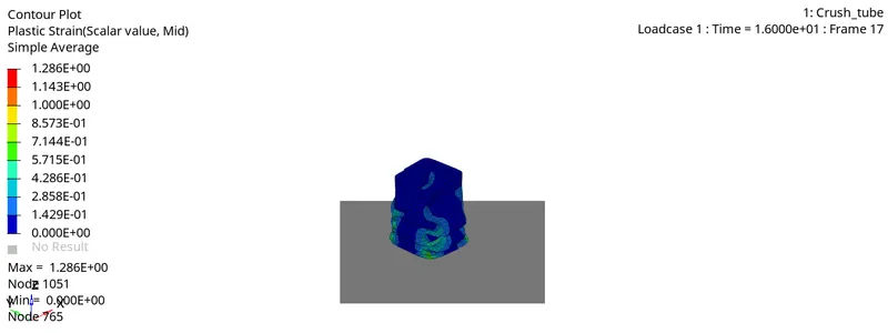
- here the maximum value is 1.286E+00 occurs at node 1051.
von mises stress:
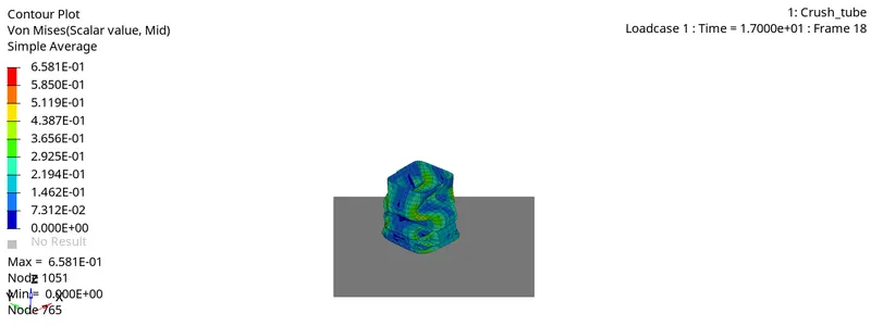
- here the maximum value is 6.581E-01 kN/mm^2 occurs at node 1051.
Displacement:
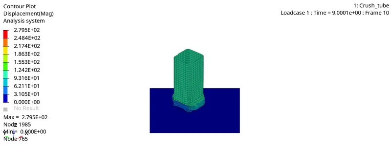
- Here the maximum value is 2.795E+02 mm occurs at node 1985.
In Hypergraph:
internal energy:
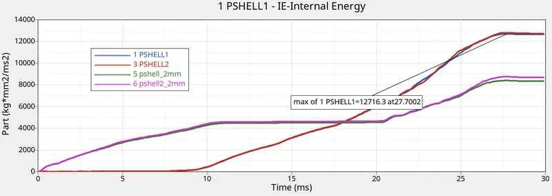
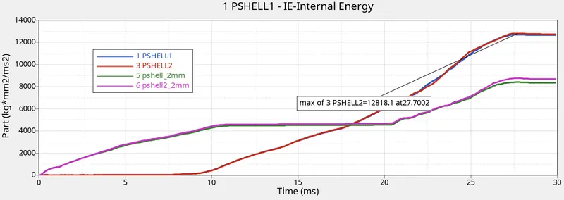
- the component with 3mm thickness has the maximum value of 12716.3 J at 27.7002 ms and 12818.1 J at 27.7002 ms.
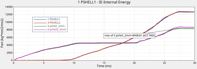
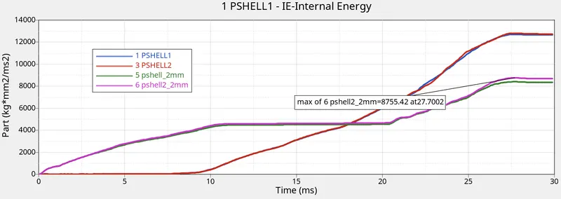
- the component with 2mm thickness has the maximum value of 8408.81 J at 27.7002 ms and 8755.42 J at 27.7002 ms.
contact energy:
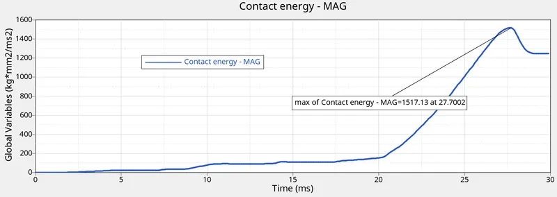
- the maximum value is 1517.13 J at 27.7002 ms.
rigid wall forces:
normal force:
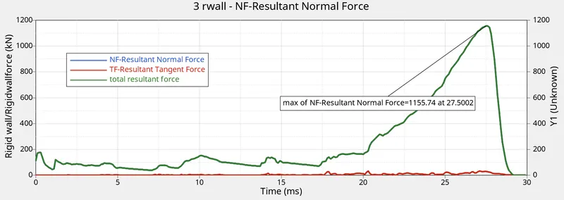
- it reaches its maximum value of 1155.74 KN at 27.5002 ms.
tangent force:
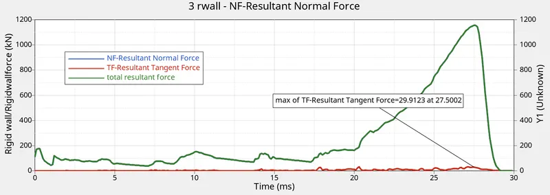
- the maximum value of the tangent force is 29.9123 KN at 27.5002 ms.
total resultant forces:
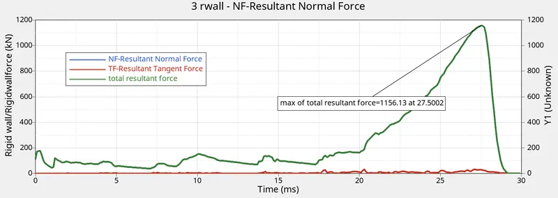
- the total resultant forces trace the same path as the normal forces, reach its maximum value of 1156.13 KN at 27.5002 ms.
CASE 5:
The simulation run is done using the Radioss solver with the contact interfaces type2 and type7 as shown in case 1 with a notch at the middle of the component as shown below,
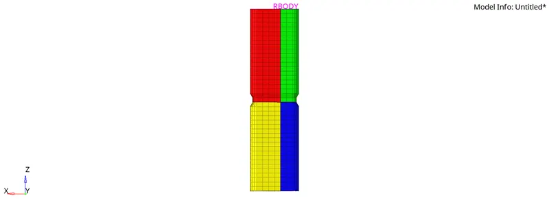
- created a notch at the middle of 4.038 mm as per the notch in the given model.
procedure:
- imported the given .rad file in the Hypermesh.
- using the options such as geom--> surface-->from FE, surface edit-->offset (shift+f9), tools-->project(shift+f7), created the notch at the middle of the component.
- a simulation run is done with Radioss solver.
- imported the .h3d file and .T01 file in Hyperview and Hypergraph respectively.
- the animation for von mises stress, plastic strain, and displacement is observed and the graph for internal energy, contact energy, rigid wall forces are plotted.
observation:
- the deformation starts right at below the notch area when compared with case 1, as shown below,
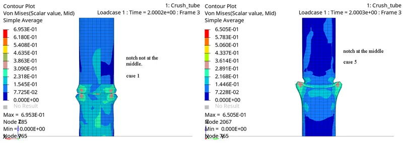
- the number of cycles at the end of the simulation is 111900 and the energy error is -3.3% and the mass error is 0.
In Hyperview:
plastic strain:
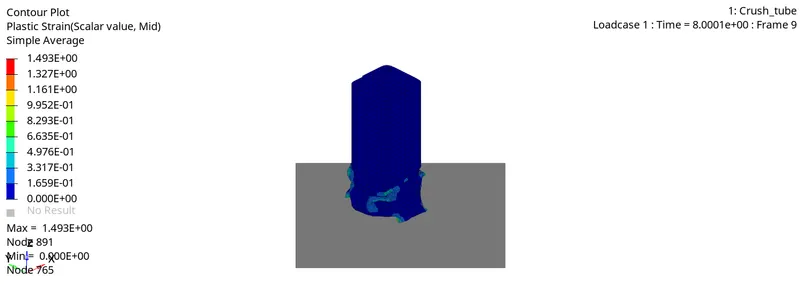
- here the maximum value is 1.493E+00 occurs at node 891.
von mises stress:
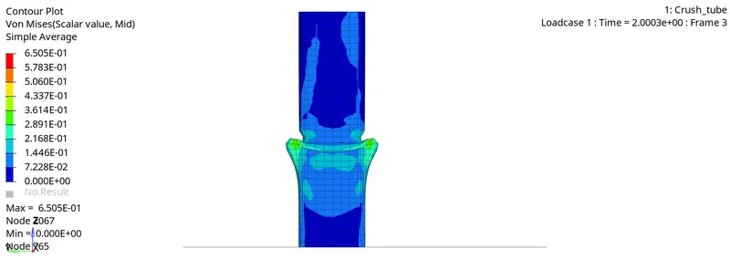
- here the maximum value is 6.505E-01 kN/mm^2 occurs at node 2067.
Displacement:
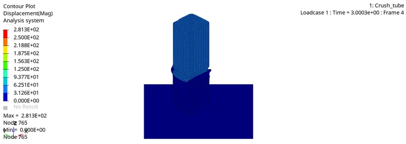
- Here the maximum value is 2.813E+02 mm occurs at node 765.
In Hypergraph:
internal energy:
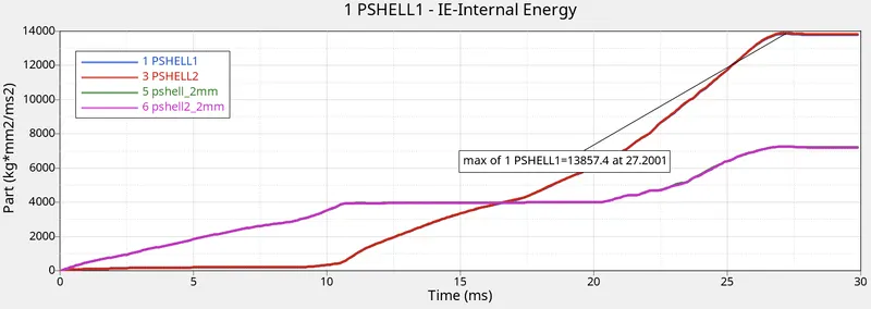
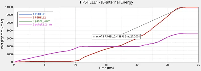
- the component with 3mm thickness has the maximum value of 13857.4 J at 27.2001 ms and 13896.3 J at 27.2001 ms.
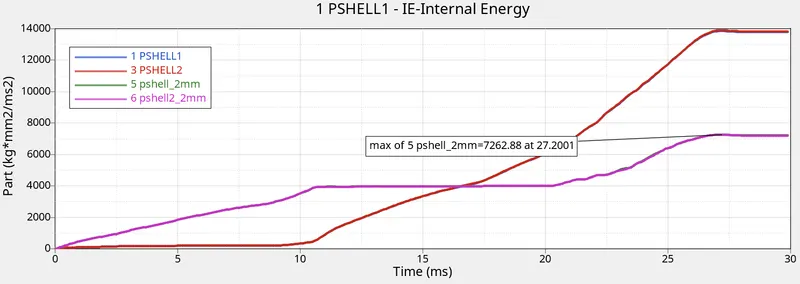
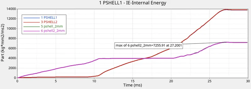
- the component with 2mm thickness has the maximum value of 7262.88 J at 27.2001 ms and 7255.91 J at 27.2001 ms.
contact energy:
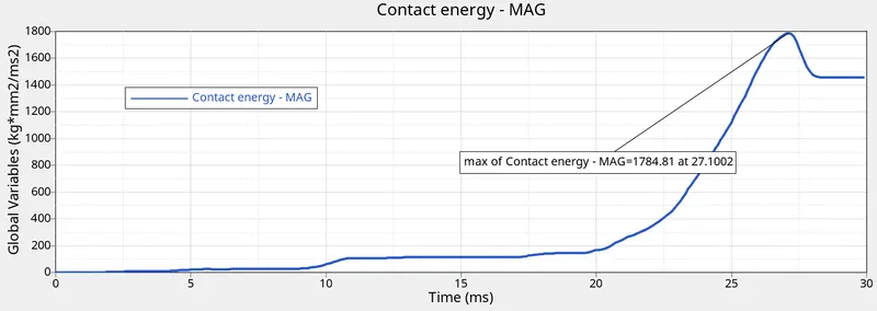
- the maximum value is 1784.81 J at 27.1002 ms.
rigid wall forces:
normal force:
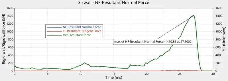
- it reaches its maximum value of 1410.81 KN at 27.1002 ms.
tangent force:
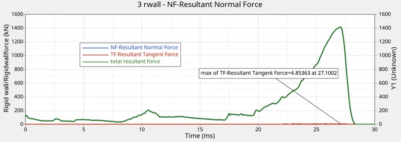
- the maximum value of the tangent force is 4.85363 KN at 27.1002 ms.
total resultant forces:
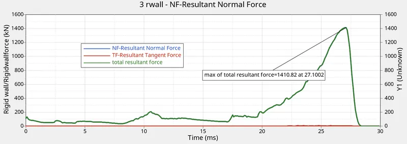
- the total resultant forces trace the same path as the normal forces, reach its maximum value of 1410.82 KN at 27.1002 ms.
CASE 6:
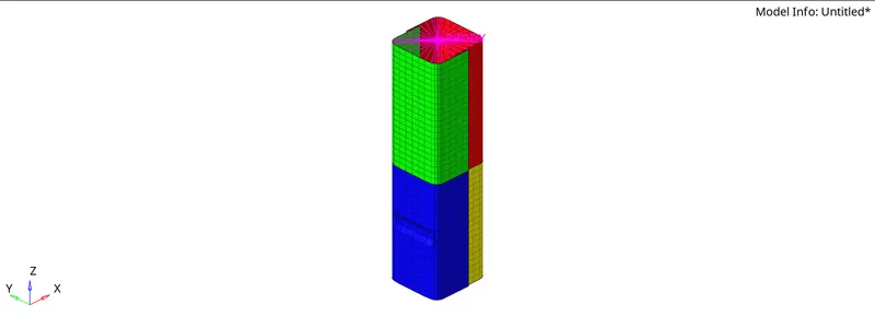
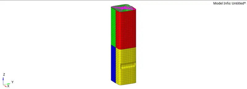
The simulation run is done using the Radioss solver with the contact interfaces type2 and type7 as shown in case 1 with the notches on the opposite faces of the component as shown below,
procedure:
- imported the given .rad file in the Hypermesh and simulation run is done with Radioss solver.
- using the options such as geom--> surface-->from FE, surface edit-->offset (shift+f9), tools-->project(shift+f7),created the notches on the opposite faces of the component.
- imported the .h3d file and .T01 file in Hyperview and Hypergraph respectively.
- the animation for von mises stress, plastic strain, and displacement is observed and the graph for internal energy, contact energy, rigid wall forces are plotted.
observation:
- Here the buckling occurs at the notch area, then the deformation develops throughout the component until it is impacted on the rigid wall.
- the number of cycles at the end of the simulation is 75500 and the energy error is -4.0% and the mass error is 0.
In Hyperview:
plastic strain:
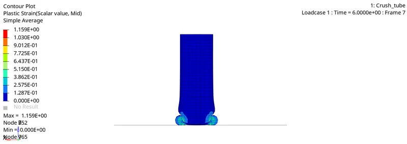
- here the maximum value is 1.159E+00 occurs at node 952.
von mises stress:
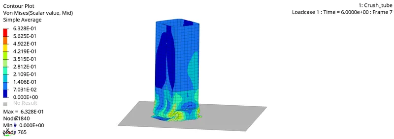
- here the maximum value is 6.328E-01 kN/mm^2 occurs at node 1840.
Displacement:
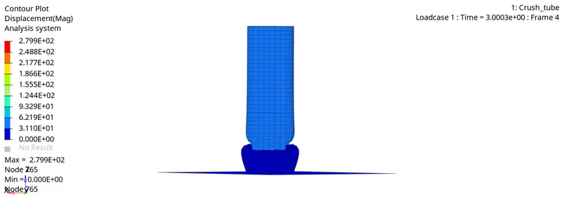
- Here the maximum value is 2.799E+02 mm occurs at node 765.
In Hypergraph:
internal energy:
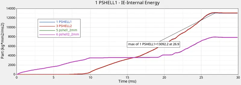
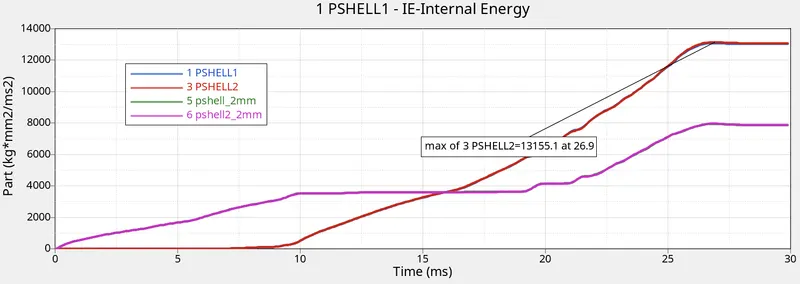
- the component with 3mm thickness has the maximum value of 13092.2 J at 26.9 ms and 13155.1 J at 26.9 ms.
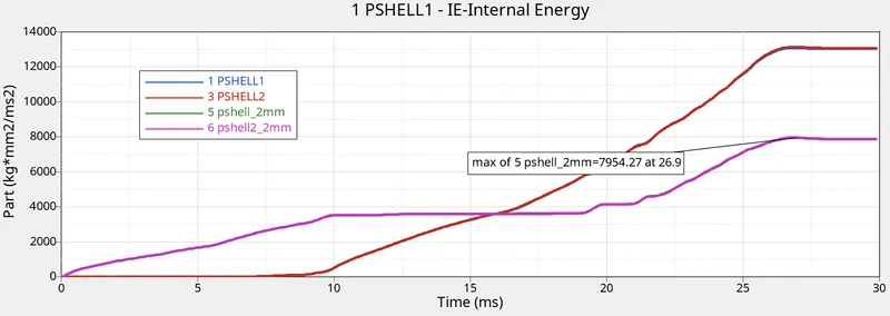
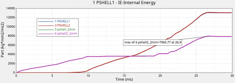
- the component with 2mm thickness has the maximum value of 7954.27 J at 26.9 ms and 7965.77 J at 26.9 ms.
contact energy:
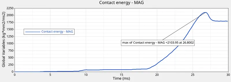
- the maximum value is 2103.95 J at 26.8002 ms.
rigid wall forces:
normal force:
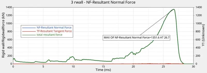
- it reaches its maximum value of 1351.6 KN at 26.7 ms.
tangent force:
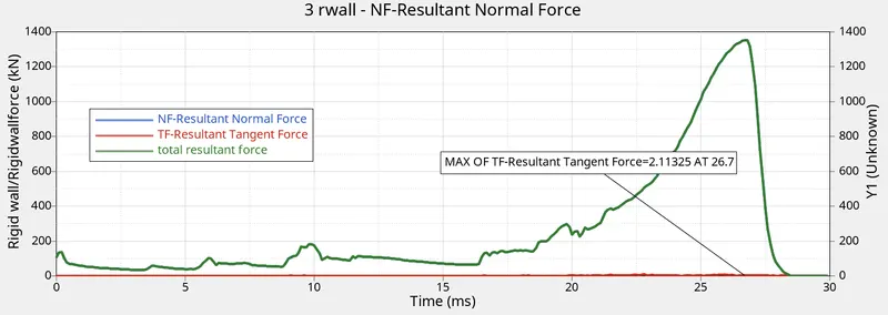
- the maximum value of the tangent force is 2.11325 KN at 26.7 ms.
total resultant forces:
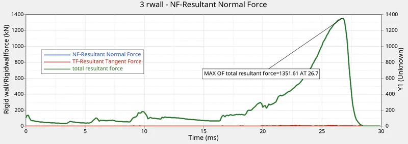
- the total resultant forces trace the same path as the normal forces, reach its maximum value of 1351.61 KN at 26.7 ms.
COMPARISION:
- Here case 1 and case 2 have similar results, but in case 2 the initial penetration is taken care of by the inacti option.
- In case 4 the deformation starts at the bottom of the component, whereas in case 1 the deformation starts at the notch.
- when comparing the results with the notch and without the notch, Case 4 has less energy dissipation of 2.9% than the case 1 of 3.8%.
- In case 1, the contact energy reaches 2029.77 J greater than case 4 is 1517.13 J.
- The total resultant force which acts on the rigid wall is less in case 4 than case 1.
- With no boundary condition case 4 has the tangent force of 29.9123 J is greater than case 1 is of 1338.18 J.
- In case 1, the number of cycles at the end of the simulation is greater than in case 4.
- When comparing the results with the type of contact interface, in case 3 with type 11, the components get separated during the impact whereas in case 1 the components tied up due to type 2.
- Case 3 has a high energy dissipation of 5.9% than case 1 and case 2 of 3.8%.
- In case 3, the number of cycles at the end of the simulation is 99900 whereas in case 1 and 2 is 83400.
- In type 11, the tangent force is 10.2514 J is greater than type 2 and type 7.
- The contact energy in case 3 reaches 3044.47 J is greater than all cases with type 2 and type 7.
- The total resultant rigid wall forces reach 1823.69 J than all other cases.
- Case 3 has the highest energy dissipation of 5.9 % than all other cases.
- The mass error remains Zero in all cases.
- Case 5 has the highest number of simulation cycles than all other cases.
result:
internal energy:
- when a body strained, some energy will get stored in the body and that energy is the strain energy or internal energy. That straining effect can be due to gradually applied load or suddenly applied load or load with an impact.
- the strain energy stored in the body is equal to the work done by the applied load in compressing the body.
In General, According to the formula, strain energy U=`sigma`^2 * A*L/2E
so, the strain energy depends on the area of the cross-section and the length of the body. so, from the results, Pshell 1 and Pshell_2 components having a thickness of 3mm has high strain energy when compare to Pshell_2mm and pshell 2_2mm components having 2 mm thickness.
The notch is the area where the deformation starts to develop all through the body. so change in the internal energies /work done by load varies with the location of the notch in the body. The buckling starts at the notch and then the down part and then the whole component gets impacted on the rigid wall.
Effect of the notch in the component:
The notch is the area where the deformation starts to develop all through the body. This can be proved from case 4, where the deformation starts at the bottom of the component. Also, the total internal energy, contact energy, rigid wall forces all depends on the presence of notch and location of the notch in the component, because it provides stiffness to the component so that is the reason we get the less resultant normal force on the rigid wall in case 4 when compare to other cases with the notch.
CONCLUSION:
Hence,
- The bumper assembly model is meshed with a 6mm element size.
- The study and comparison of the contact interface type 2, type 7, and type 11 are done.
- The study is made over the influence of notch in simulation.