Assignment 5
OBJECTIVE - Create the mesh for bumper assembly with element size 6mm and to analyze or compare the different case of interface 7, interface 11 and with or without notch model.
PROCEDURE -
- first open the bumper system model by import geometry. It will appear in wireframe mode , then click on shadow mode to appear surface.
- Then go for automesh and mesh the model with the given element size of 6mm.
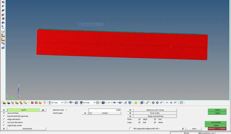
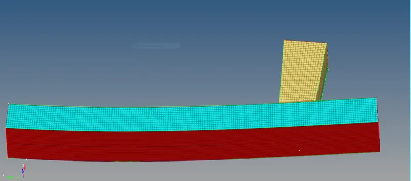
- then give spot or seam weld connection to the component where two surfaces overlap or meet.
Model setup -
The component of the crush box are of different thickness. The part of closer to rigid wall are of 2mm thickness whereas the part away are of 3mm thickness. Due to overlapping component, the 3mm component will have initial penetration pre-defined. To check for penetration, a penetration check perform on model.
There is one material card defined by M2 plastic johnson card with the properties of a steel material and initial velocity is -13.3 m/s in Z axis direction. The boundary condition of the rigid body are defined and only Z axis translation is permitted all other motion are restricted.
Case 1 - Run the crash tube model as it is and type 7 contact defined to prevent initial penetration and other parameters are set default.
The model is run with default setup using radioss solver
check the energy or mass error %.
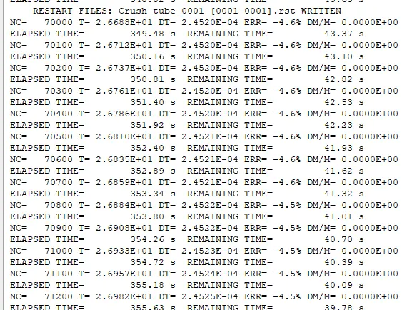
Energy error is - 4.6% which is acceptable range
mass error is 0.
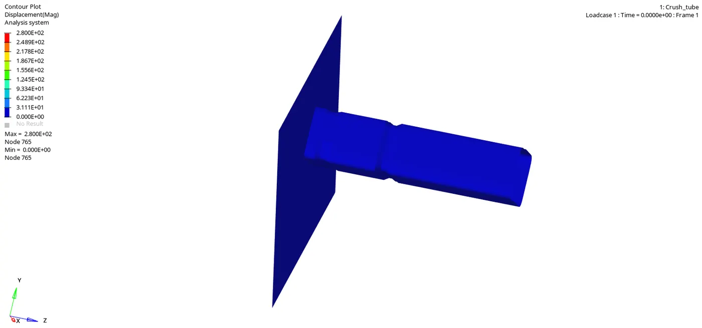
From the animation it is seen that the notch cause stress concentration and buckling of tube start from notch area. Once the lower part is deformed then area only above the notch start to deform
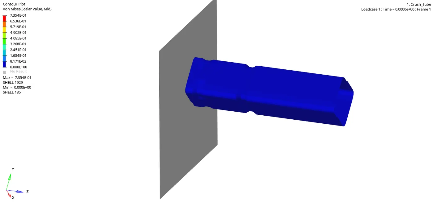
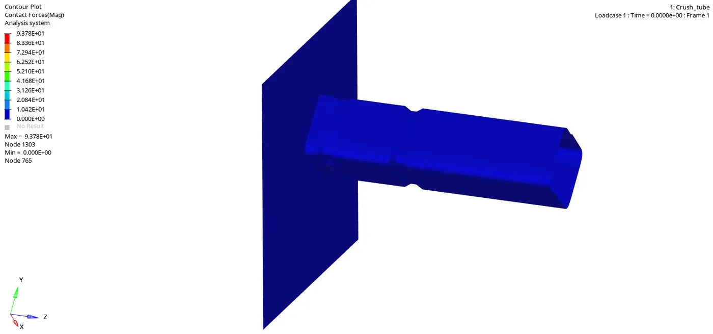
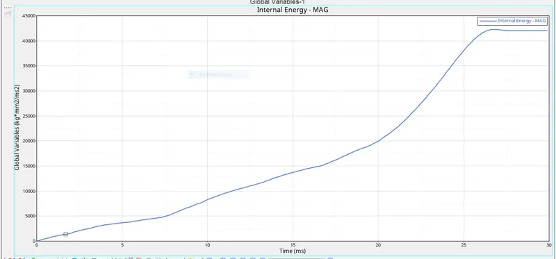
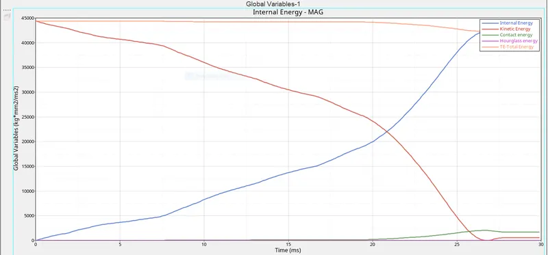
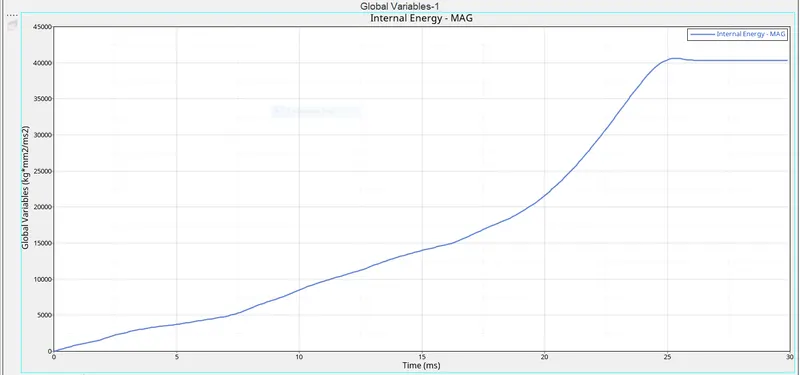
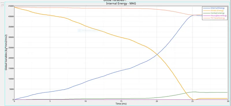
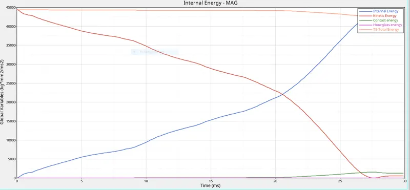
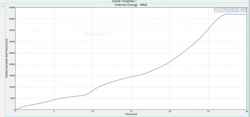
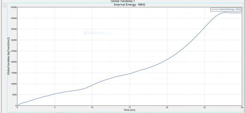
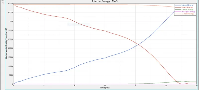
Internal energy is indication of energy absorbed by the tube as internal strain energy. So as the crushing begins Internal energy increase till 26 ms, at this point the tube has absorbed maximum energy .Thus the energy applied to the tube is not completely tansfer to the rigid wall and major part is converted into internal strain energy.
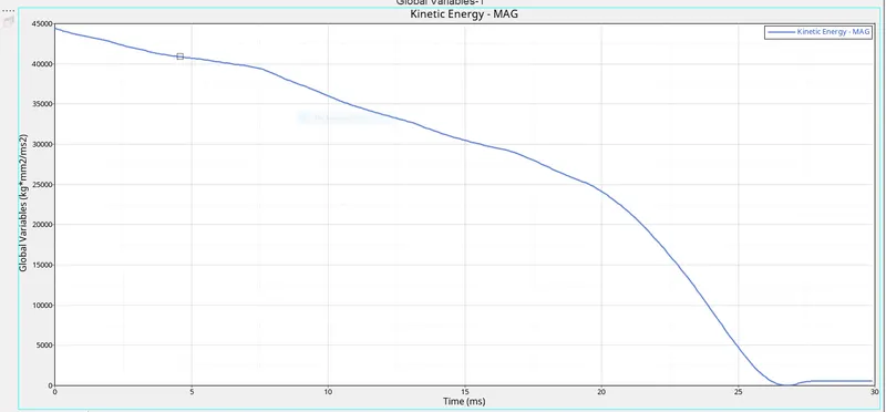
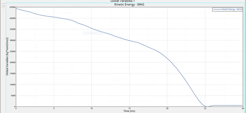
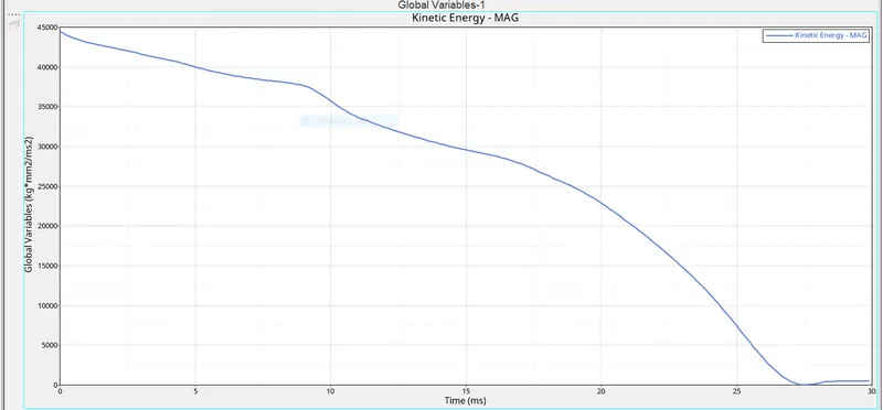
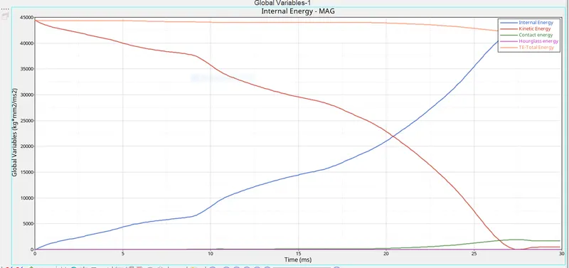
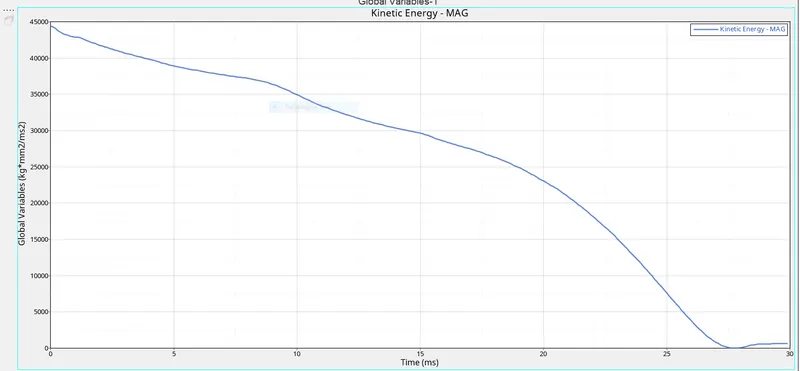
The kinetic energy decreased with time as expected and at the end slightly increase is seen due to rebound of the tube due to normal reaction force. Total energy is the sum of kinetic and internal energy.
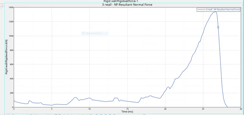
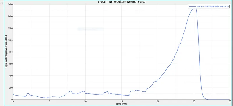
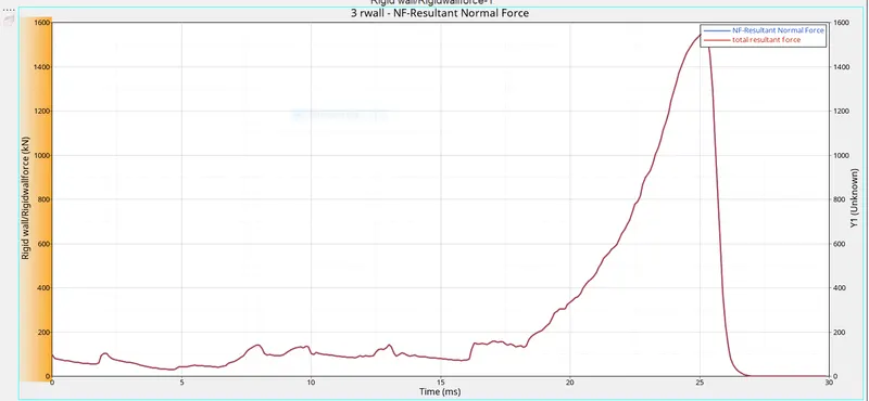
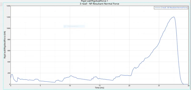
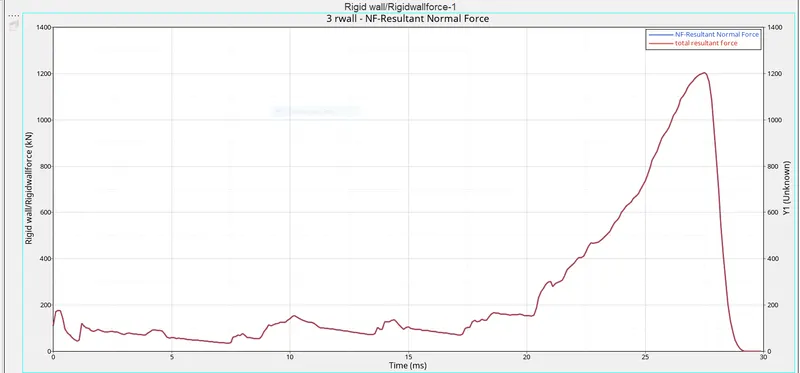
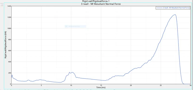
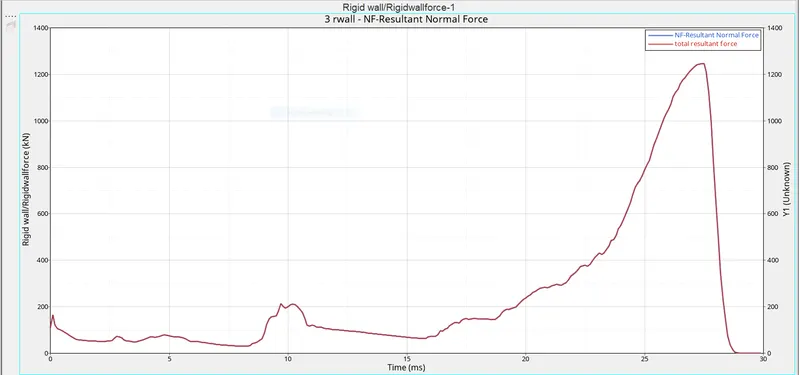
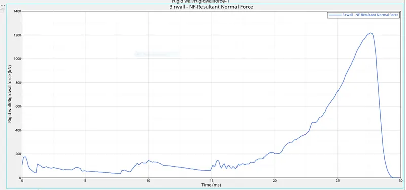
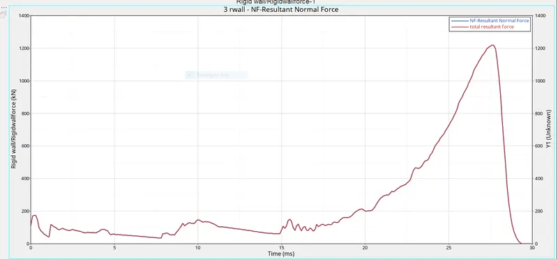
The rigid wall forces are peak at after 25ms because at that time the tube has been completely crushed
Case 2 - Change the inacti into 6 and run the model.
In type 7 contact , The value of Inacti is change to 6.
Inacti 6 is recommended to prevent initial penetration if exist.
Then model is run with setup using radioss solver
check the energy or mass error %.
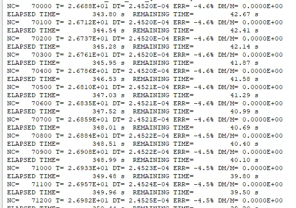
Energy error is - 4.6% which is acceptable range
mass error is 0.
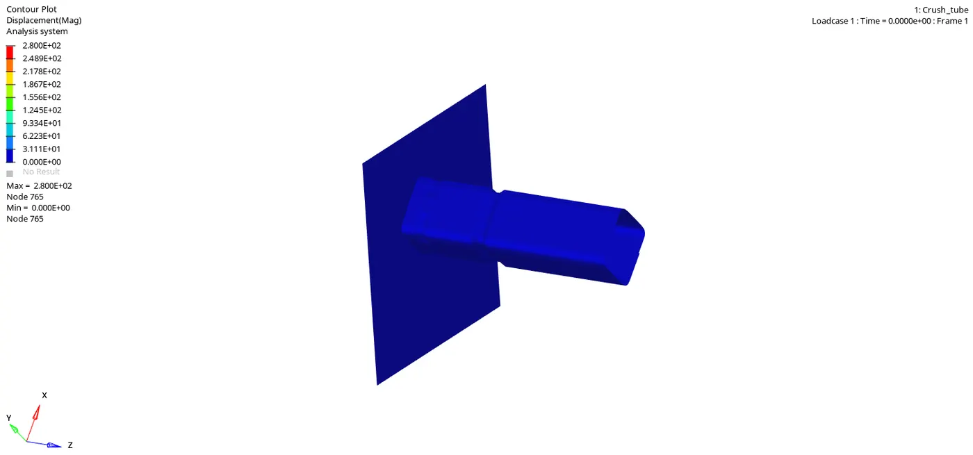
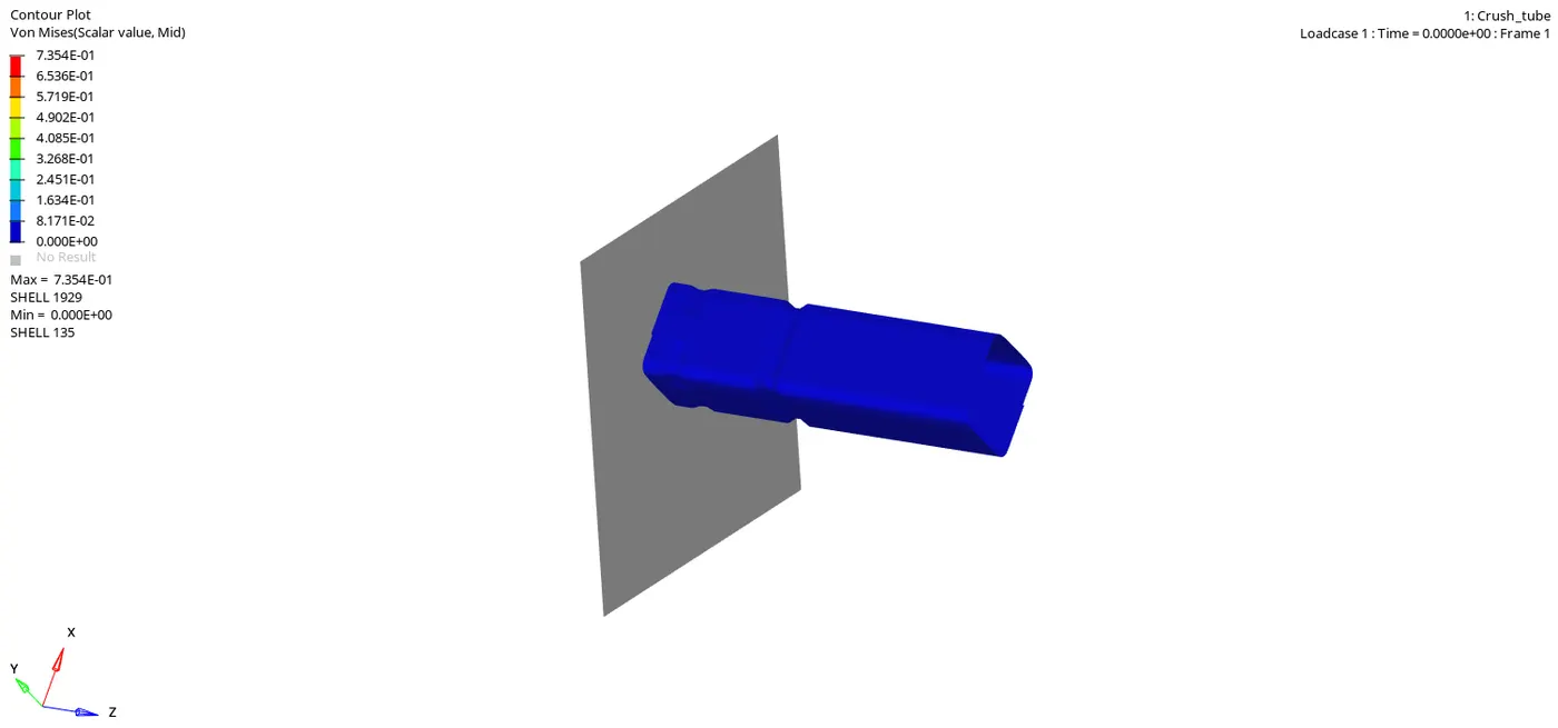
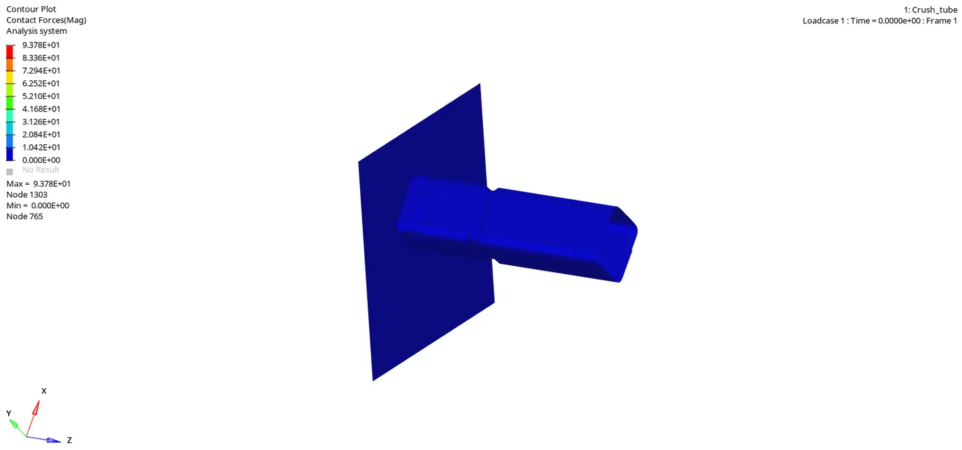
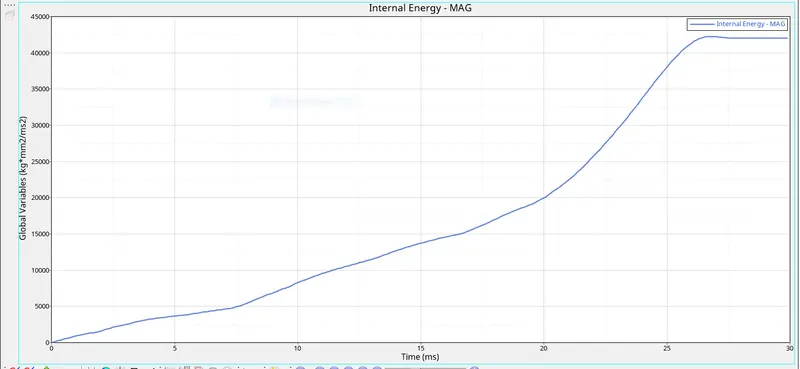
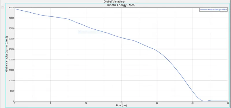
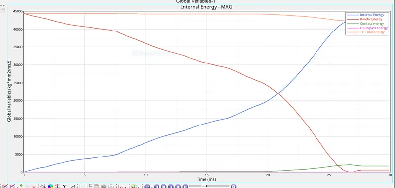
The energy curve of case 2 is similar as case 1. This indicate that there are no initial penetration in the model.
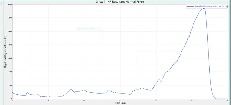
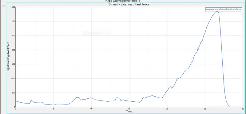
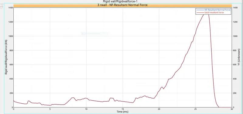
The rigid wall forces are not affected by the inacti value change.
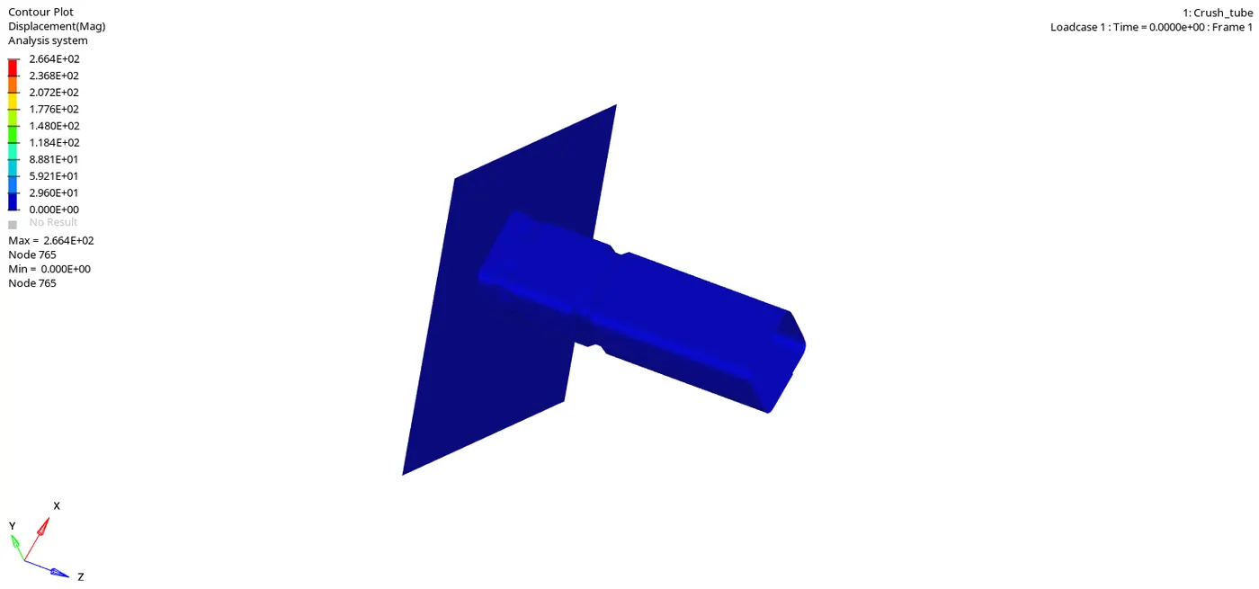
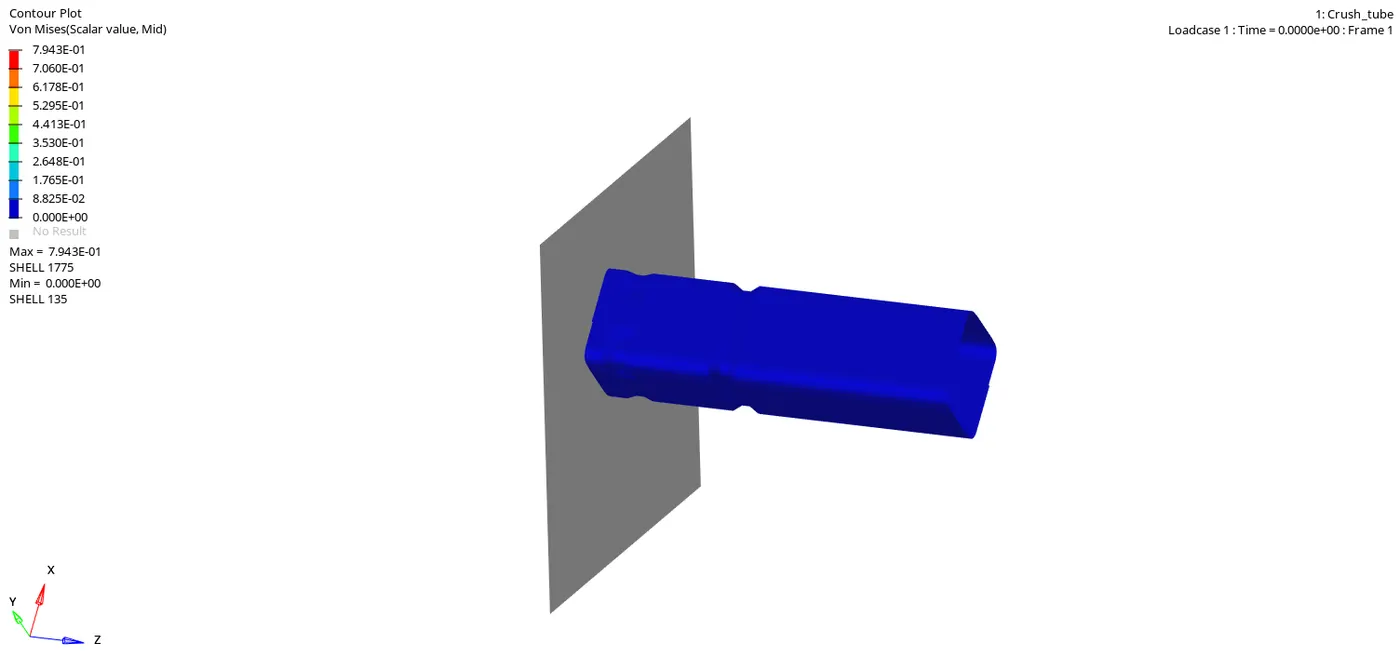
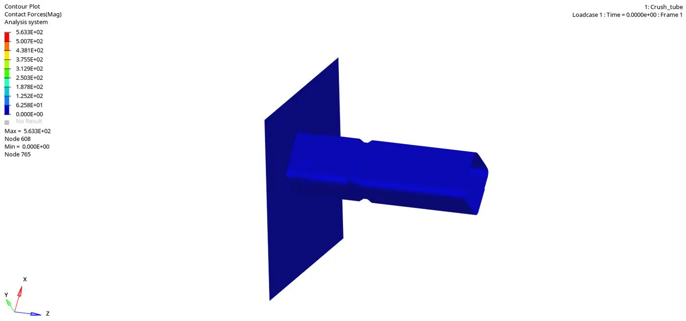
Case 3 - Create the type 11 contact and run.
In this case Edge to Edge contact is defined .
Type 11 contact parameter are
Igap = 3
inacti = 6
stiffness = 4
stmin = 0
Idel = 2
Gap min = 0.5
coulomb friction = 0.2
Then model is run with setup using radioss solver
check the energy or mass error %.
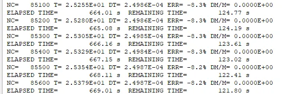
Energy error is - 8.2% which is acceptable range
mass error is 0.
Case 4 - Remove both notches and remove boundary condition on rigid body node then run.
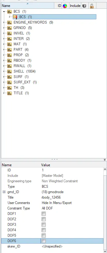
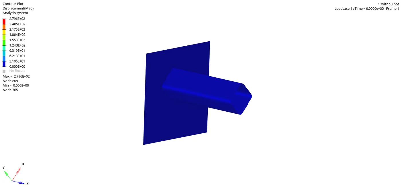
In this case , The notches are removed by using a option of translate or align node . A notch free model is obtained now and also remove the boundary condition of rigid wall and rest of the conditions stay the same.
Now run the model in radioss.
Then model is run with setup using radioss solver
check the energy or mass error %.
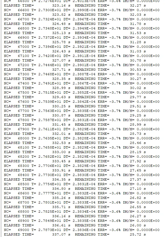
Energy error is - 3.7% which is acceptable range
mass error is 0.
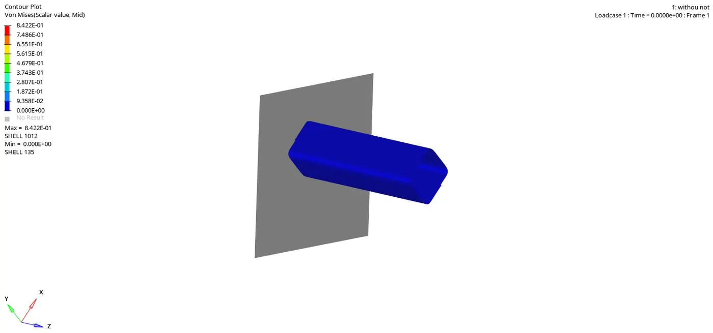
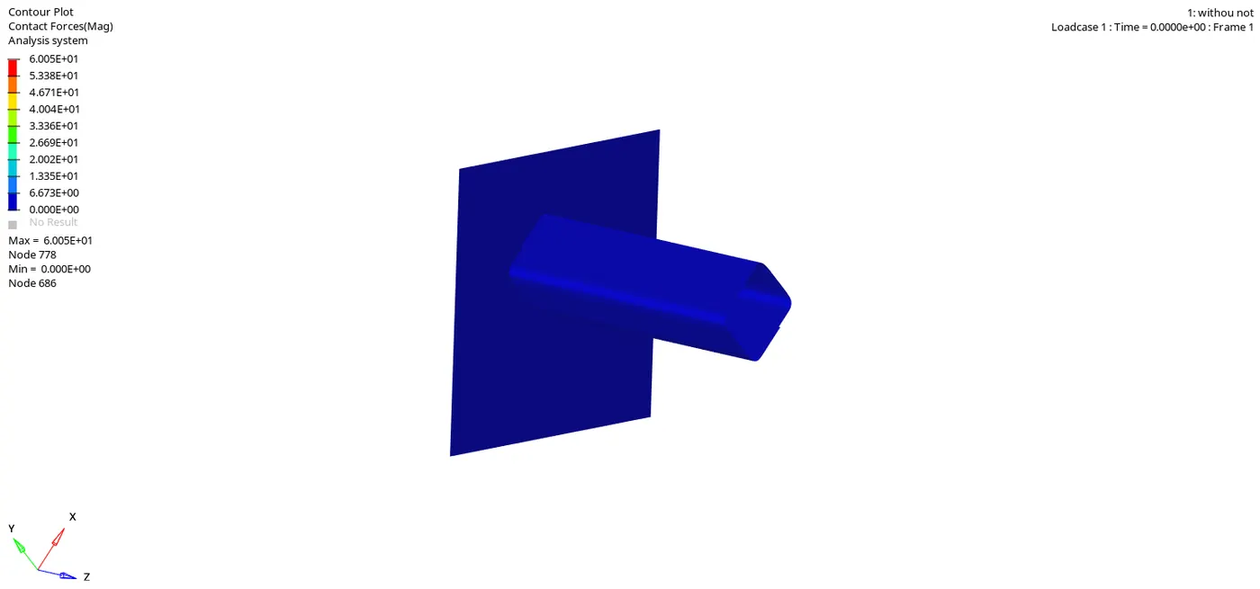
Due to removal of boundary condition the rigid body can has all 6 degree of freedom and can translate or rotate along all three axis.
The removal of notch causes the deformation to start from the bottom of the tube. In previous three cases the deformation start from notch area due to high stress concentration factor.
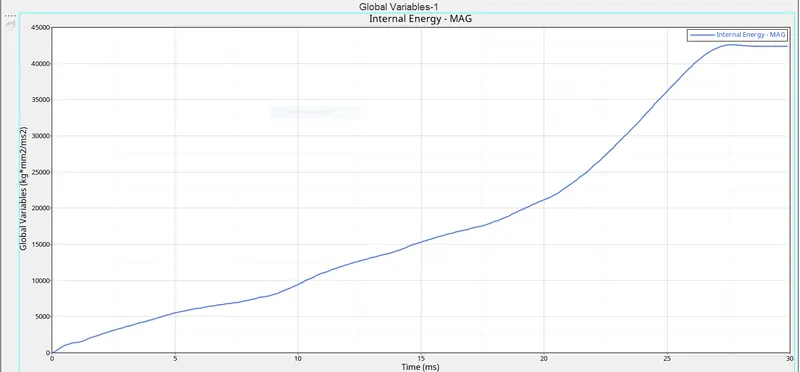
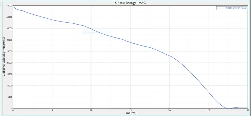
As kinetic energy decrease , the internal energy increase. The total energy decrease in the end as some amount of energy is lost as contact energy. Thus there is a situation at the end of simulation where the part of tube is pressed against another part of tube , this increase the contact energy in the end.
Case 5 - Create a new notch in the middle ,select the whole section and run.
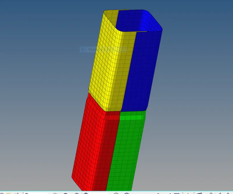
In this case we created a notch at the middle of the tube.
Then model is run with setup using radioss solver
check the energy or mass error %.
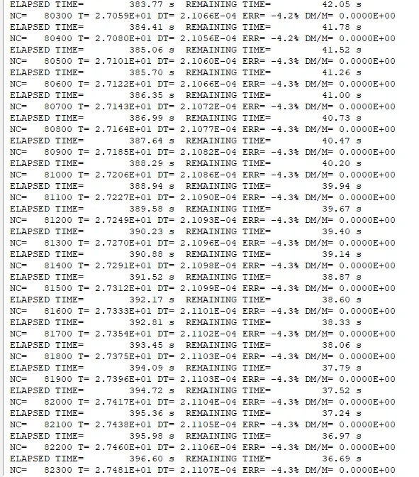
Energy error is - 4.3% which is acceptable range
mass error is 0.
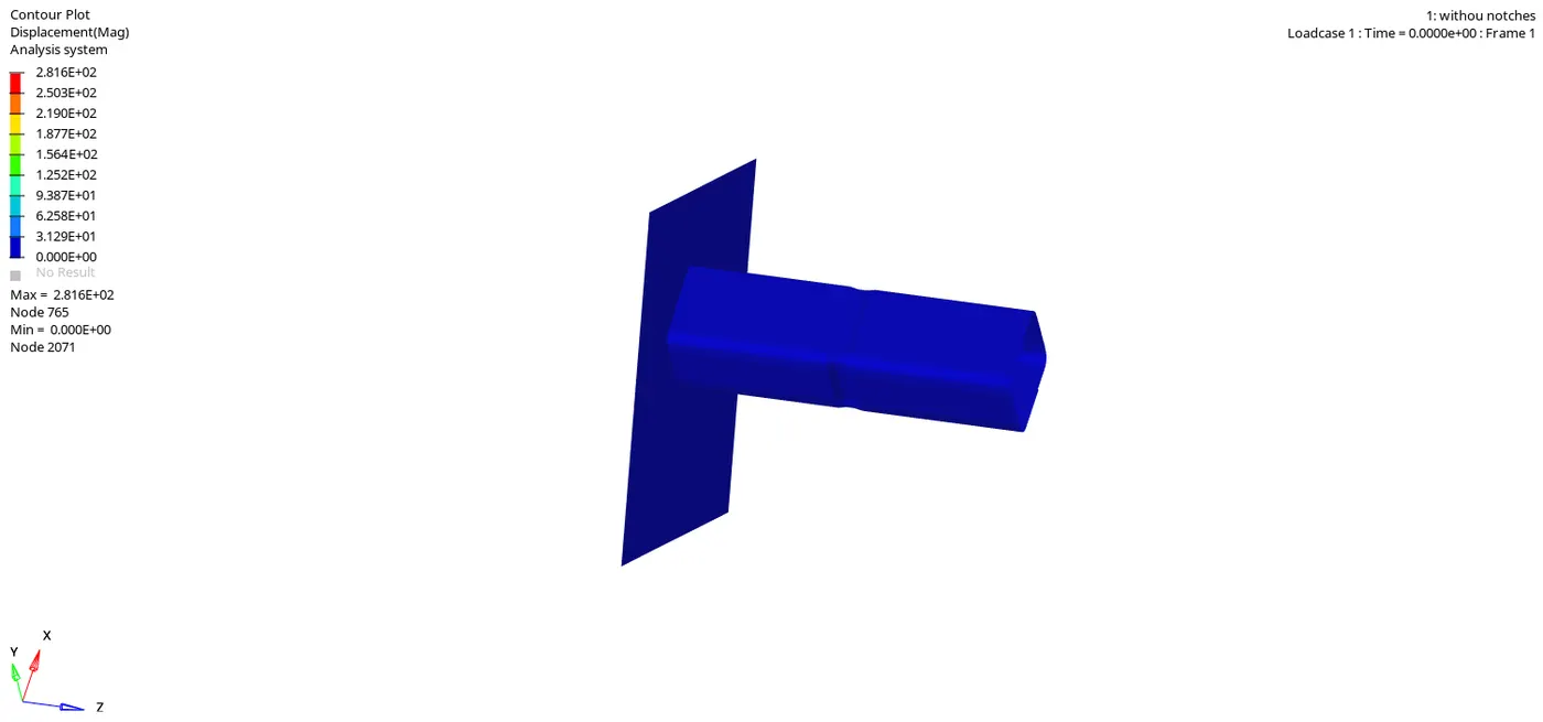
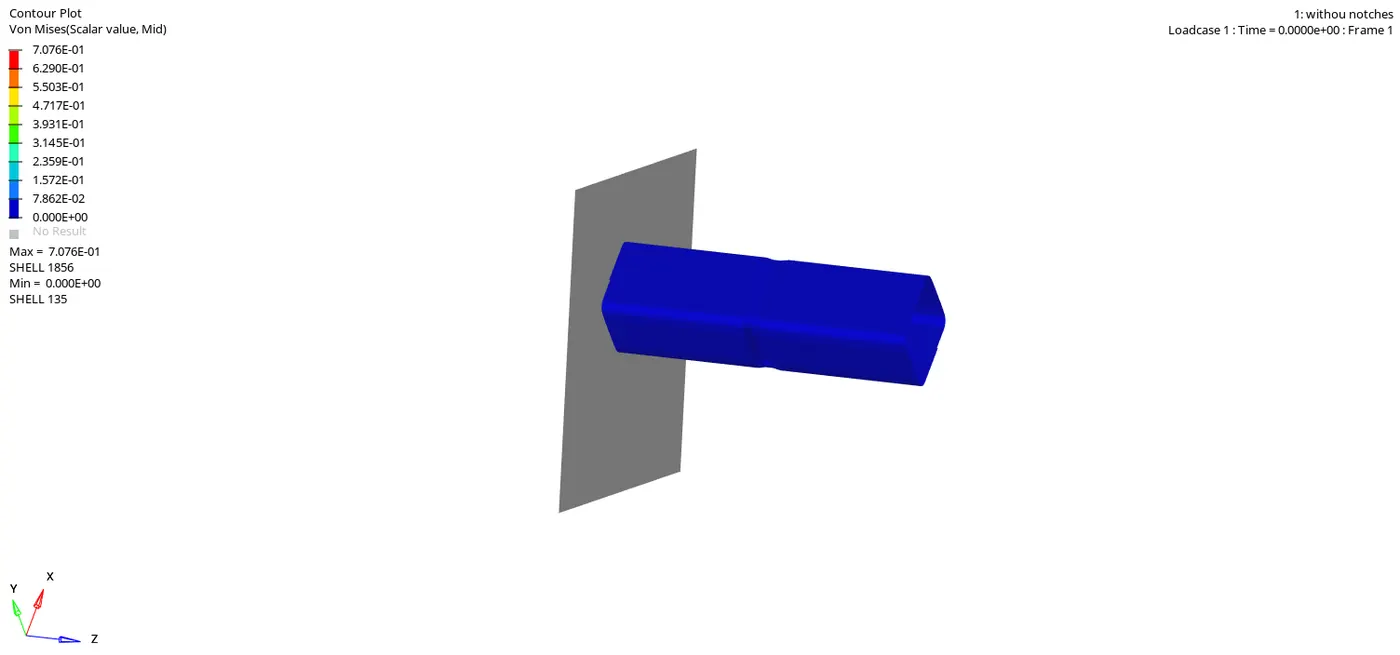
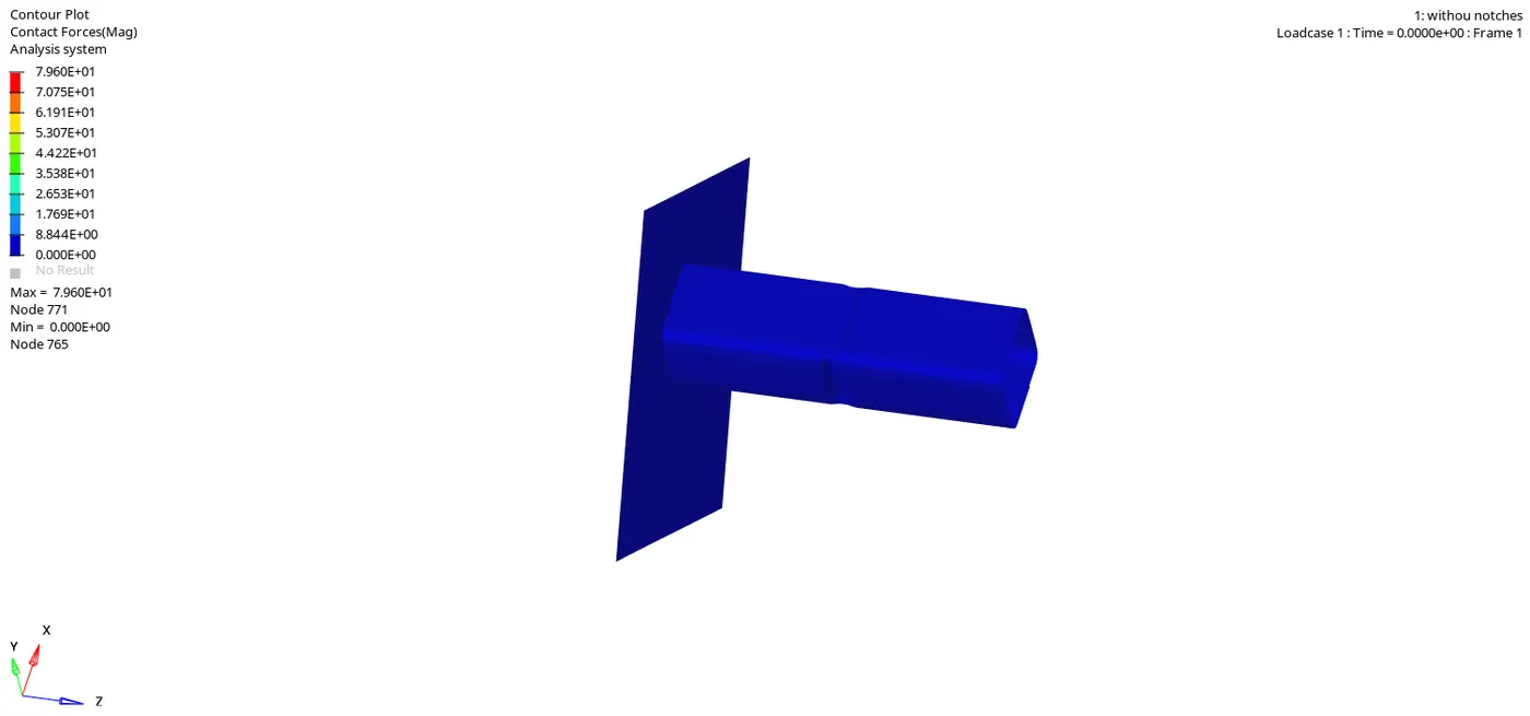
Similar to first three case ,Here also the deformation start from the notch area. Once the part below the notch is deformed then only top part of tube is deformed.
Case 6 - Create a new notch with nodes only from opposing 2 faces and run.
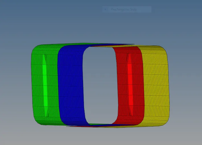
In this case two oppsite face notch kept in middle of the tube.
Then model is run with setup using radioss solver
check the energy or mass error %
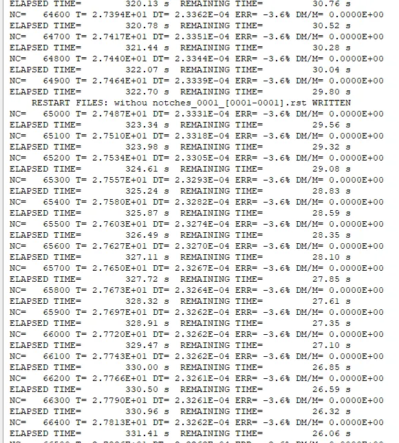
Energy error is - 3.6% which is acceptable range
mass error is 0.
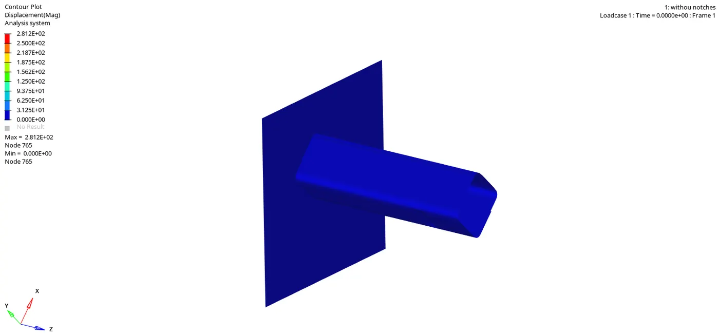
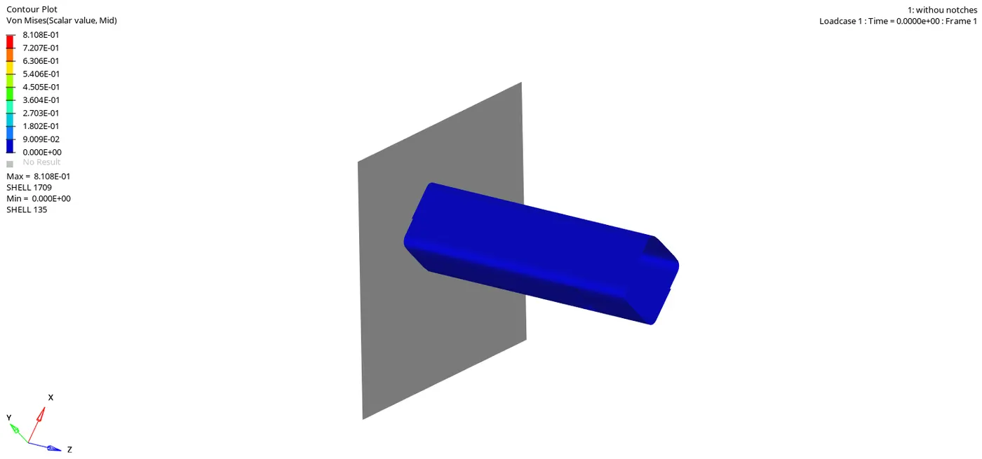
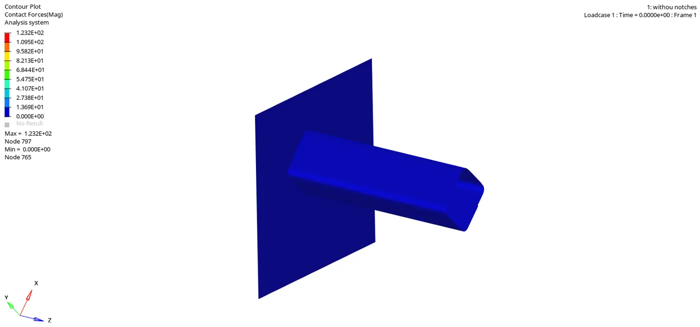
Due to reduction of notch area, the buckling effect induce by notch in case 6 is lesser than as compared to case 5 which have notch all four side.
Thats why there is decrease of rigid wall forces as compared to case 5 rigid wall force plot.
In this case only the side with notches buckle and buldge outward but in case 5 all 4 side deform outward.
Comparison and result -
Vonmises stress
Cases
The position and the presence of notch have an impact on the amount of stress generated . Notches are placed so that they can take up maximum amount of stress. Notches at the middle result in consume higher stress as compared to the notches at the end. A complete rebound action can also be seen after the tube crashes into rigid wall.hence Least stress is seen in case 5
Rigid wall forces
cases
A similar profile of rigid wall was seen in all the cases. There is no changes in rigid wall forces to change inacti value from 0 to 6 . Presence or absence of notches in the model affect the way in which rigid wall react to crash. Highest amount of forces in the rigid wall seen in case 3 wherein notches are present in of both oppsite side and minimum is seen in case 4 which is free from notches.
It is also seen that force keep increasing with a few decrement in between. this can be due to few element crashing while the crash is happening. A peak is observed in model which indicate that the whole tube has crashed. The rigid wall force then comes down to zero.
Contact energy
cases
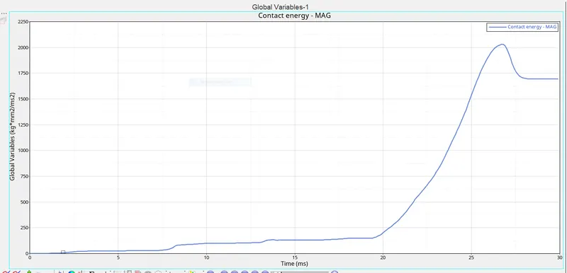
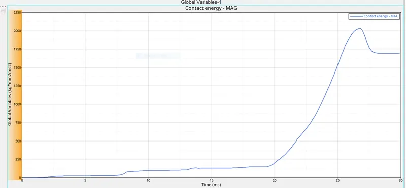
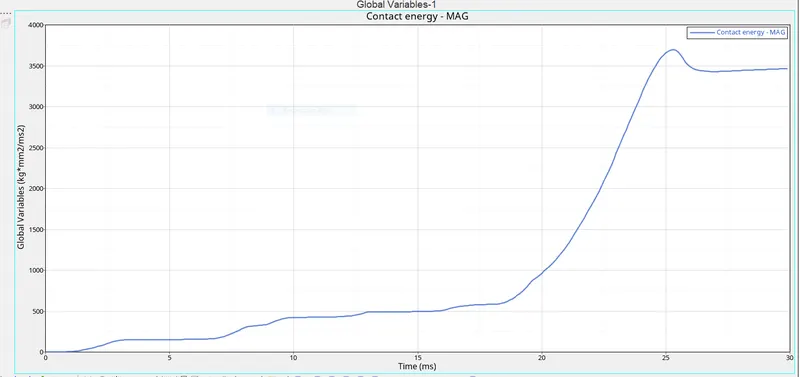
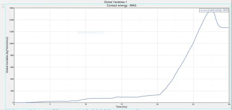
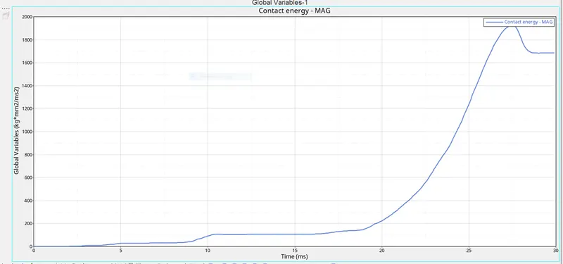
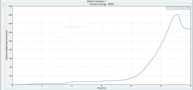
As seen above , all the cases show an increase in contact energy till the tube crashes in the rigid wall. A sligth decrease follow after the tube has completely crashed . Maximum contact energy seen in case 3 while minimum contact energy is seen in case 4.
Internal energy
Cases
Most of the vehicle kinetic energy is converted into potential or internal energy when the crash happens. This is seen in all cases as the energy reaches their maximum values toward the end of simulation. However, the time at which the system reaches its peak internal eneregy is different for all cases. When the notch are present in the model ,they are the one who absorb internal energy most. so if notches are present near the rigid wall, the peak of internal energy is reached early.
The profile of internal energy is very similar in all cases. The parts which come into contact with the rigid wall at a later stage have high internal energy as compared to parts which come in contact with the wall early in simulation. The model which have notch present experience the peak internal energy at an early stage.
Kinetic energy
Cases
At peak of crash when the velocity is effectively zero , the car acts like a compressed spring , storing potential energy . On rebounding ,Car regain a smaller amount of kinetic energy ,This time travelling backward . This small increase in kinetic energy is what we see at the end of simulation .So in overall process Kinetic energy becomes heat and spring potential energy .
Hourglass energy
Hourglass energy is zero for all cases.
Effect of notches on the simulation - Notches are the first one to get crushed in the simulation . The amount of energy absorbed by them ,its effect they have on the rigid wall as their effect on the interfaces are all dependent on position of the notch in model. Its seen that if notch present they tend to increase the buckling effect and causing the tube to deform with less amount of force. They also help in predicting the nature of deformation of a component. The disadvantage of notch is that the component fail much sooner due to stress concentration effect.
CONCLUSION - when we remove the notch we get minimum contact force and maximum von mises stress