Assignment 4-RADIOSS Material Laws Challenge
OBJECTIVE: Through this challenge, we will study different material laws in Radioss and will select the best material law for the given scenario by simulating and plotting graph.
PHYSICAL PROBLEM DESCRIPTION:-
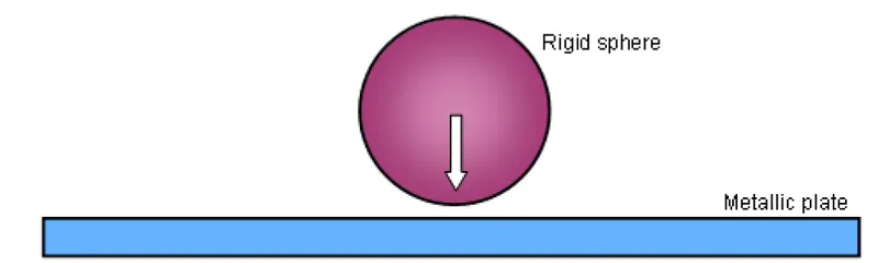
STEPS
- CASE1: Changing the model name from FAILURE_JOHNSON_0000 to Law2_epsmax_failure.Running the model as it is, without changing shell properties and modification in a material card. An optional failure model, FAIL_JOHNSON card was also used. This card is used for developing a crack in a model before element deletion.
- CASE2:Changing model name from Law2_epsmax_failure_0000 to Law2_epsmax_crack_0000. In this case we will modify ifail_sh=1,Dadv=1 and Ixfem =1. Now we will compare case1 and case2. This comparison will be based on stress generation, internal energy, crack formation, and kinetic energy
- CASE3: In this case, we will delete FAIL-JOHNSON card and run a model with new name Law2_epsmax_nofail.
- CASE4: In this case, we will assign zero value for EPS_p_max and run the model with the model name Law2.Now we will compare case 3 and case 4 on the same parameters as above.
- CASE5: In this case, we will change the material model from Law 2 to Law1.This is an independent case and will see the behavior of elastic material.
- CASE6: In this case, we will open a new model named as LAW27_0000.We will first change shell properties to recommended properties. In this case, we will find a change in material properties for brittle material.
- CASE7: Finally we will change the material model to Law36(plas_tab) and compare results with a user-defined curve and the standard curve.
CASE 1:-DEFAULT PARAMETERS
- The starter file is imported using Radioss Solver_Deck.
- the card values are shown below without changing the parameters in material card and failure card.
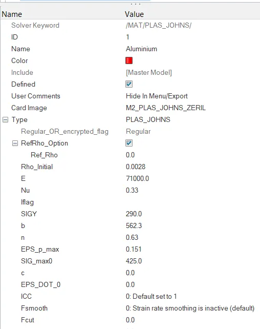
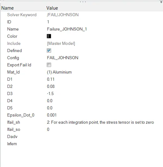
material card Failure Card
- The model is run with the Radioss Solver and saved as Law2_epsmax_faluire.
POST PROCESSING:-
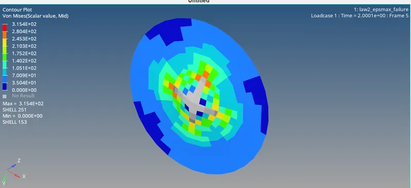
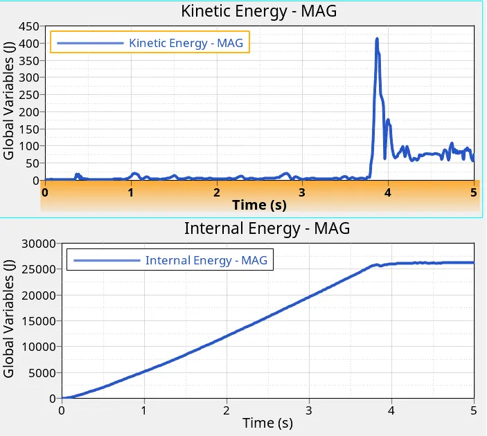
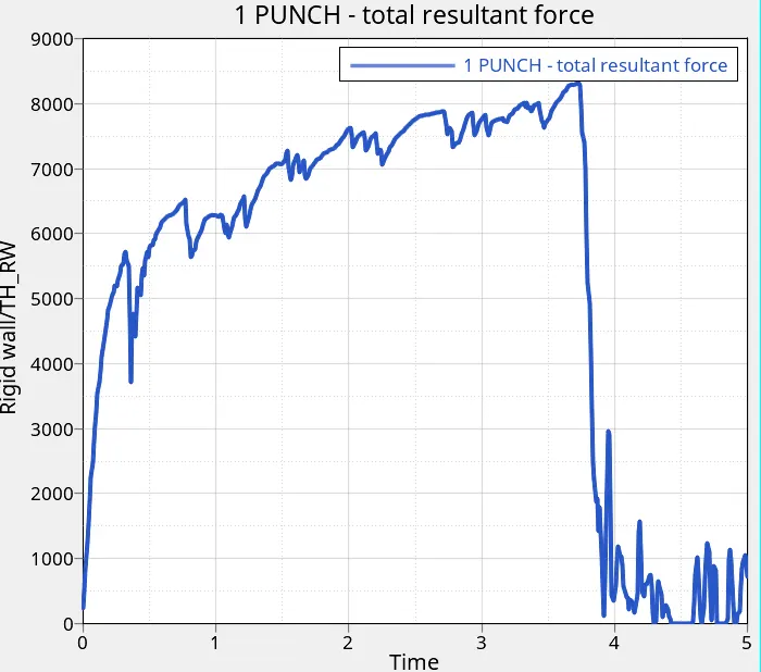
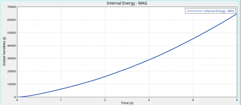
- The internal energy increases as the time increases because of elements absorbing the forces act on them .
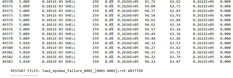
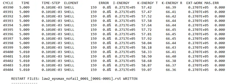
- The energy error is 0.8% and well within the allowed limit of 5% in the positive region and mass error is 0.
CASE 2:-FAIL/JOHNS card modified to crack plate
- The following modifications are made to the fail card.
-Ifail_sh =1 (Shell failure flag)
This means Shell is deleted or cracked when D=∑Δεpεf≥1">D=∑Δεpεf≥1D=∑Δεpεf≥1 for one integration point or layer. (default)
- Ifail_so is neglected because it is for solid failure
- Dadv = 1 for crack advancement (default)
- Ixfem = 1 with XFEM formulation
The model is run again using radioss solver with the file name as law2_epsmax_crack.
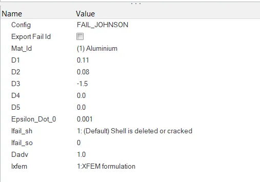
- here Ifail_sh is Shell failure flag set to 1 which will generate crack in the shell element when Ixfem is set to 1, Dadv is the criterion for the crack advancement.
POST PROCESSING:-
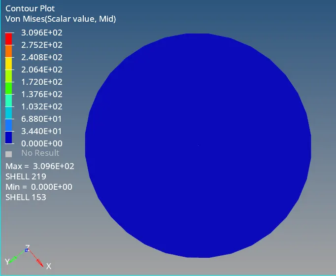
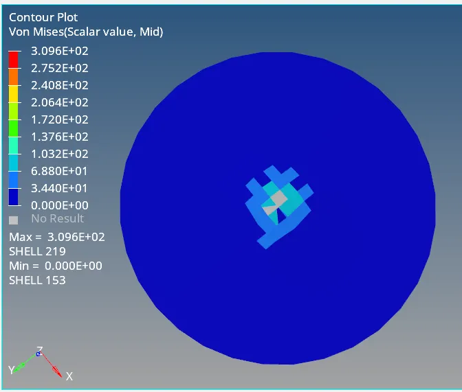
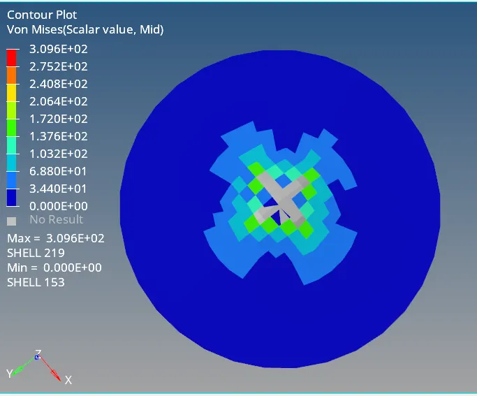
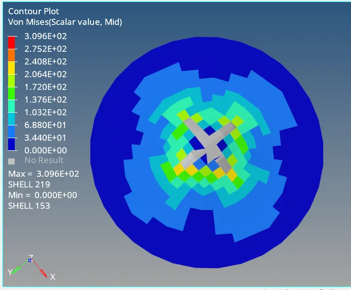
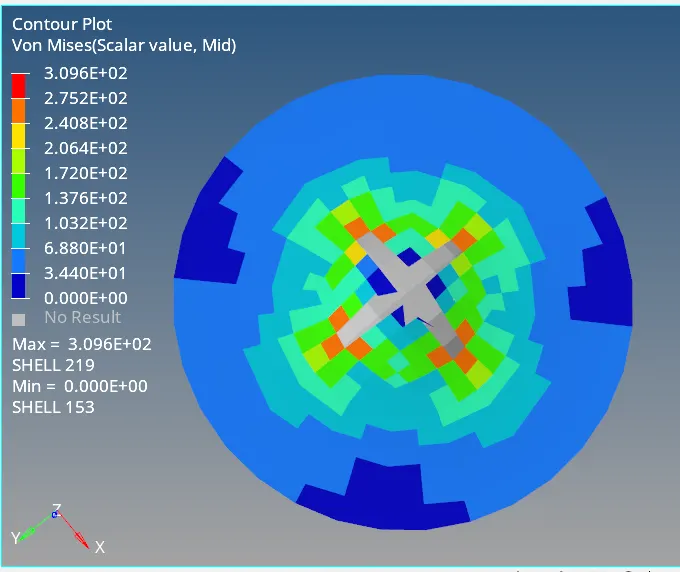
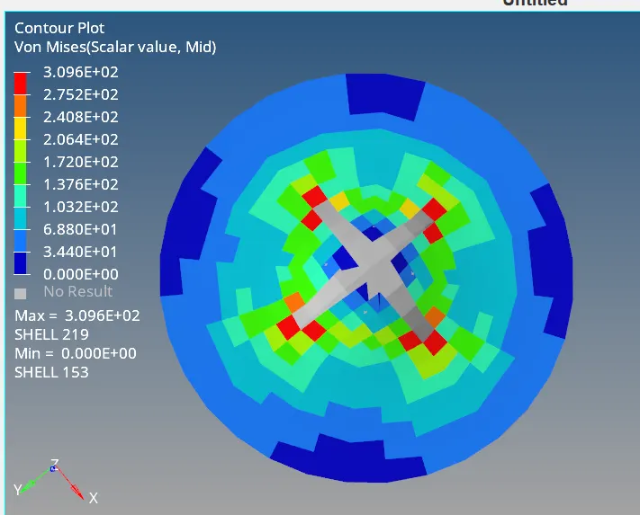
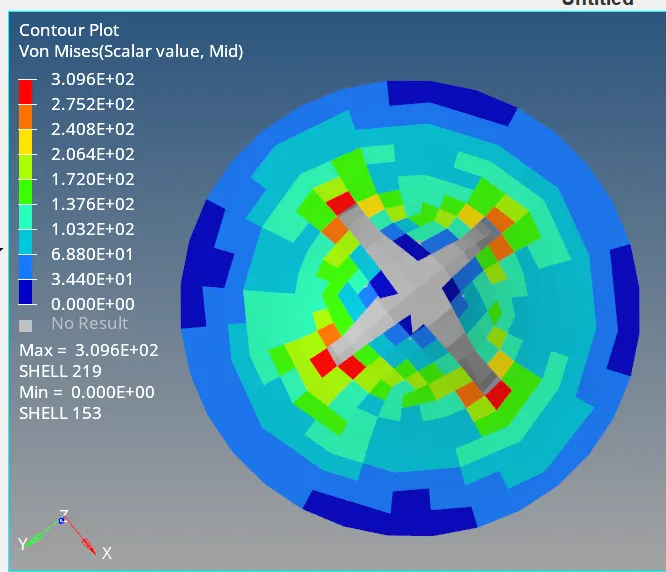
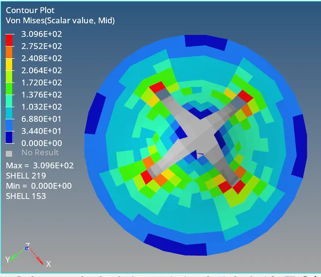
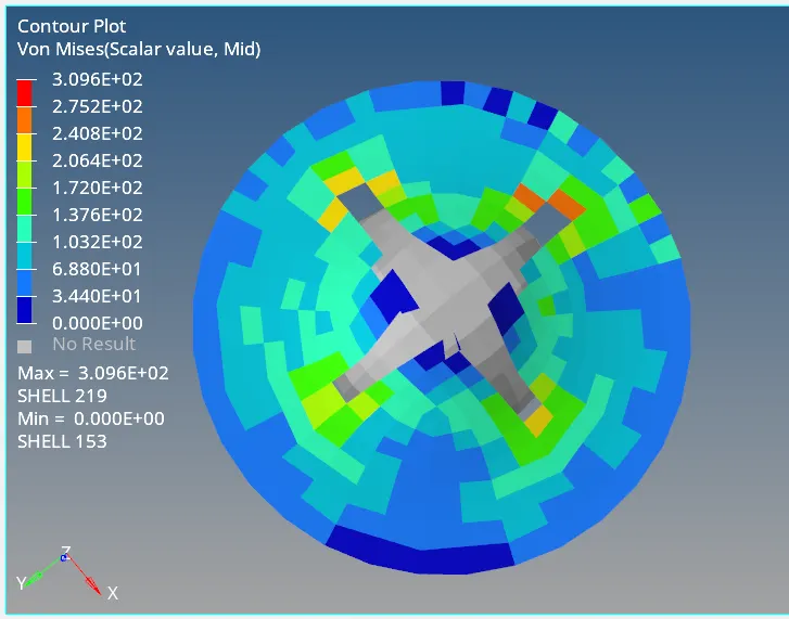
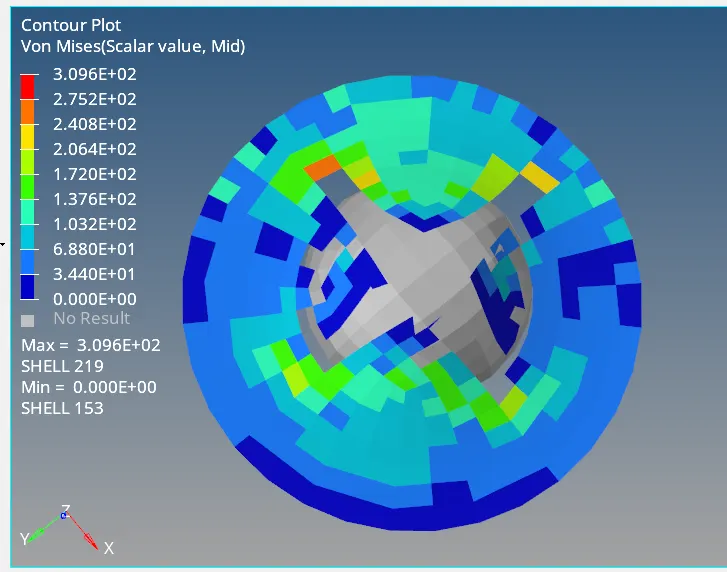
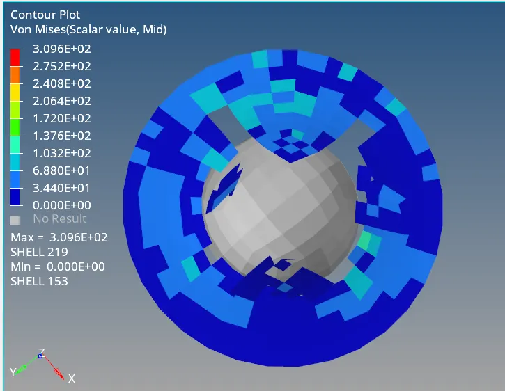
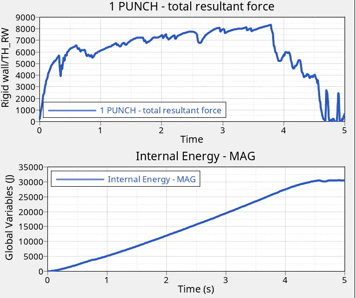
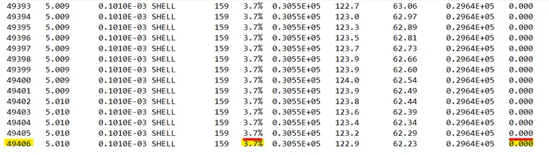
- The energy error is 3.7% and well within the allowed limit of 5%.
CASE1 and CASE2 COMPARISON
Here both model has Johnson cook material model. Both model also has an optional Failure model.
Johnson Cook Material model: This law represents an isotropic elastic-plastic material. This model expresses material stress as a function of strain,strain rate and temperature. A built-in criterion based on the maximum plastic strain is available.
In case1 Ixfem=0 and dadv=0.In case2 Ixfem =1 and Dadv=1.Ixfem decides how we want to fail the material. Default(0) will delete the whole element without cracking element.Ixfem(1) will first crack the element and then deletes.
Dadv is for crack advancement. This is only active when Ixfem =1.
Ixfem is available only for failure card. For using Ixfem material model has to be very accurate.Ixfem is best for small deformations.
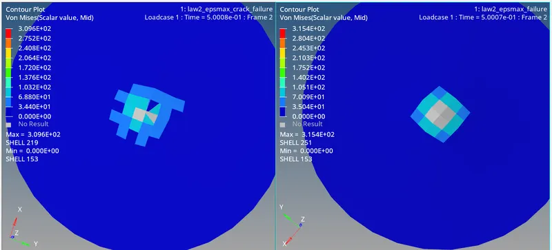
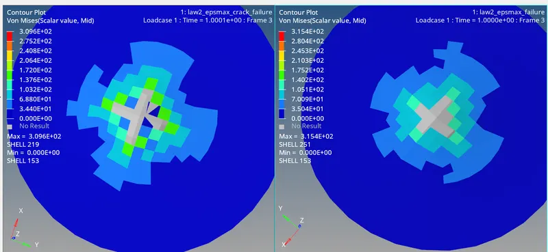
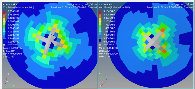
In case1 elements are deleted without crack formation. In case2 first element are cracked and then deleted. Due to this, there is delay in element deletion in case2.
Stress generation in case1 is less compared to case2.In case2 the element is first cracked and then deleted.
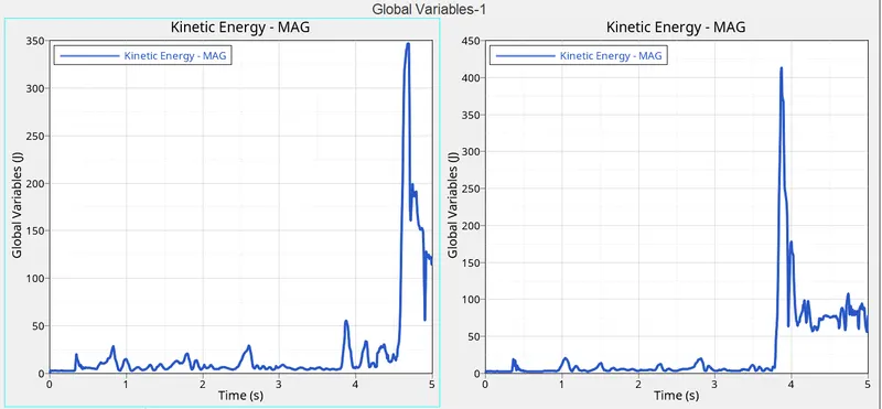
CASE2 CASE1
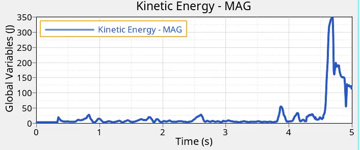
As elements are deleted first in case1, we see hike earlier than case2. Since elements are deleted slowly in case2, the graph is smoother than case1.
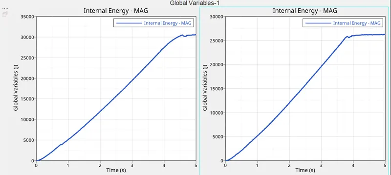
CASE 2 CASE 1
Before element deletion, internal energy increases linearly. This increase is due to the formation of strain energy in both cases.
Due to the QEPH element with inbuilt hourglass stabilization, HG energy is zero. The total energy is almost equal to internal energy.
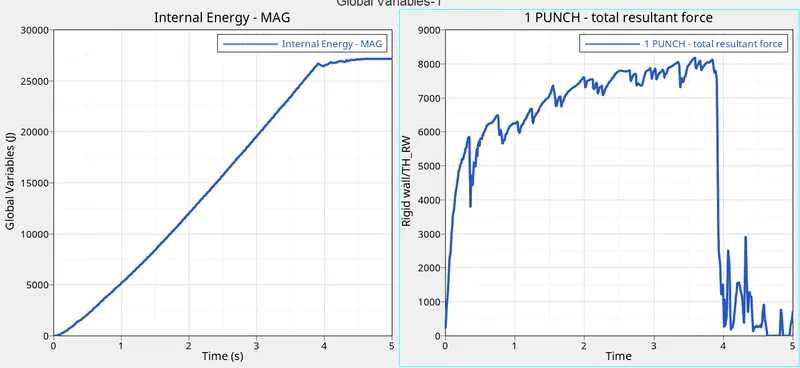
CASE 3:Delete/FAIL/JOHNS card:-
The failure card is deleted .This implies the Johnson Failure model is not applied during rupture.
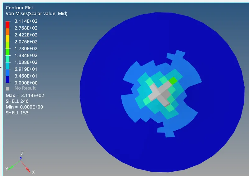
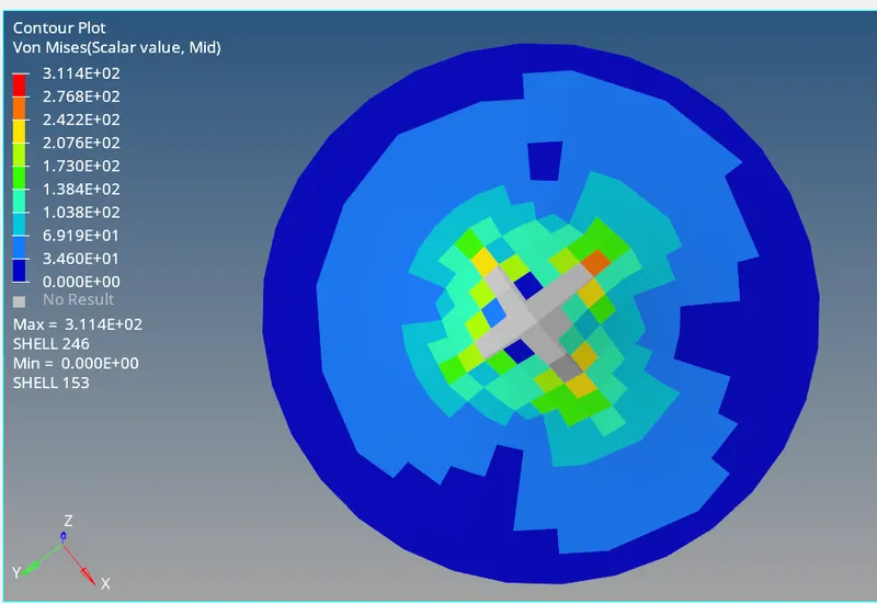
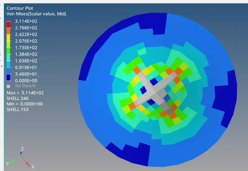
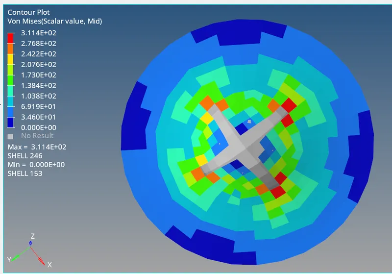
POST PROCESSING:-
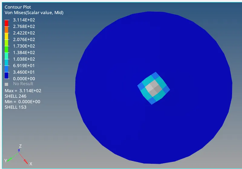
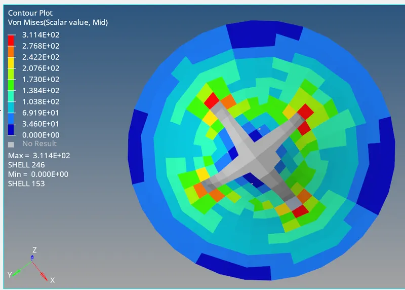
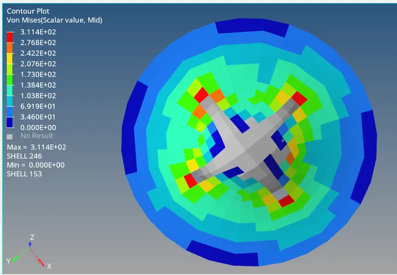

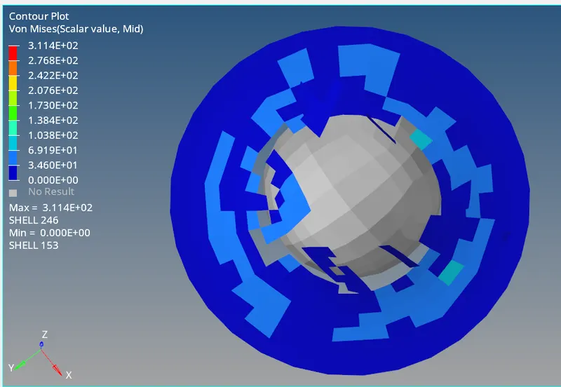
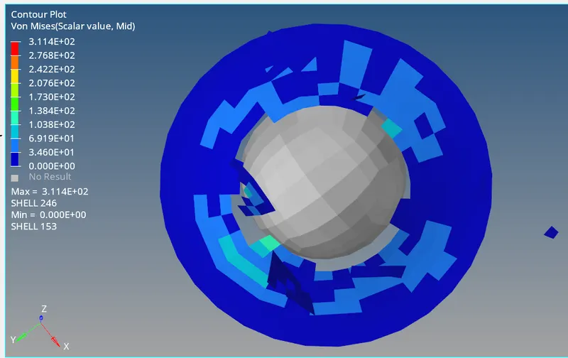
CASE 4: Delete Eps_max parameter
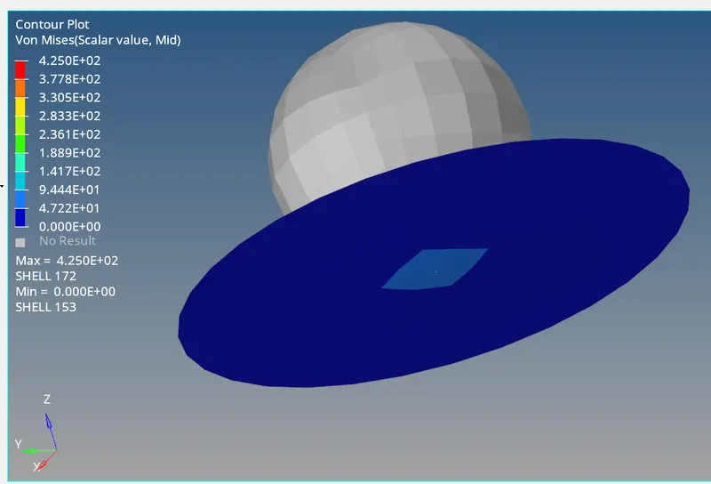
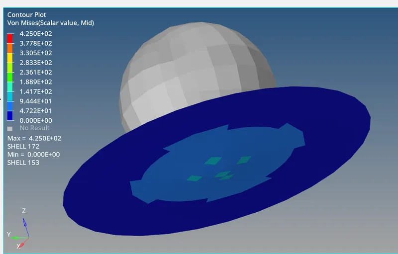
The Eps_max param which defines the plastic failure strain due to tension, compression, shear.
POST PROCESING:-
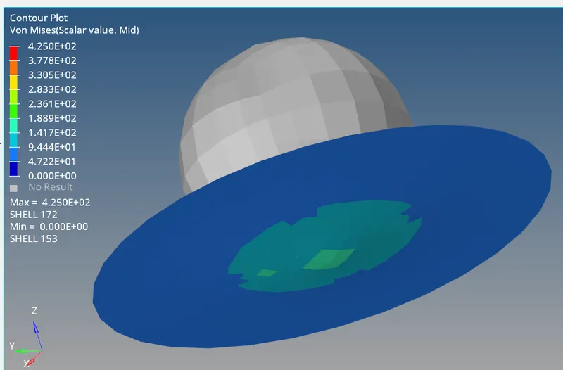
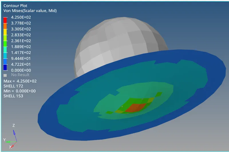
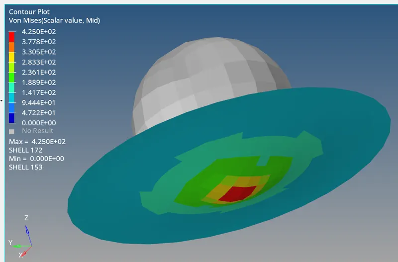
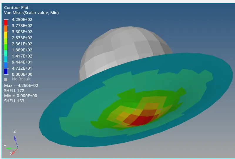
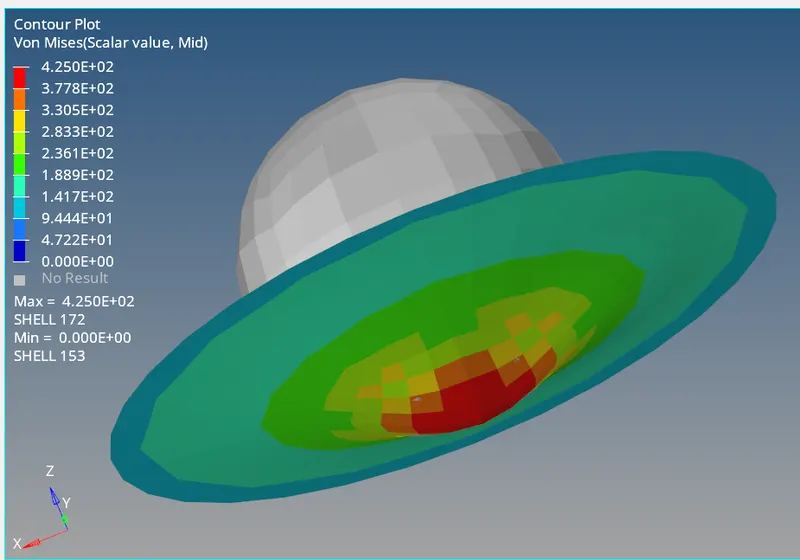
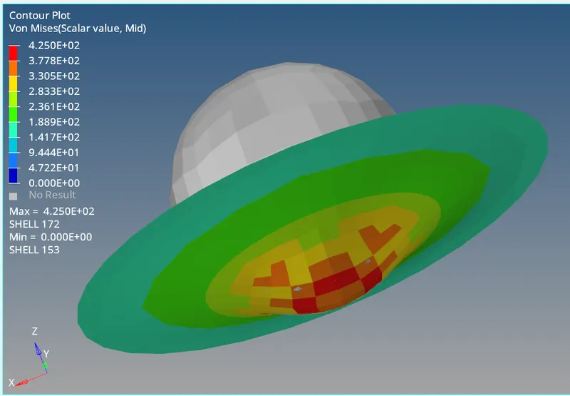
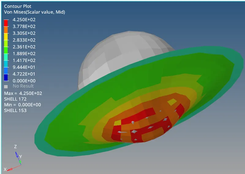
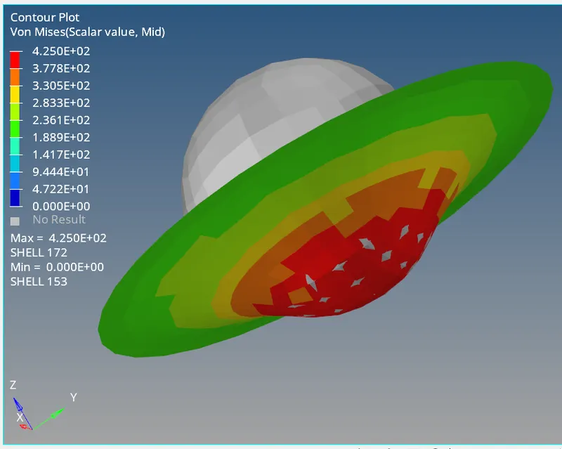
The energy and mass error is shown below
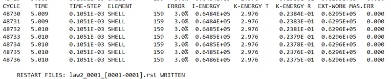
The energy error is high in this case however it is still within the acceptable limit (<5%).
CASE 3 AND CASE 4 COMPARISON:
In this case, first, we deleted Fail Johnson card.In case 3 eps_p_max was 0.151.This means the element will fail when any element reaches a strain of 15% of plastic strain.
In case 4 eps_p_max was set to 0 (default value).
case3 and case4 material card
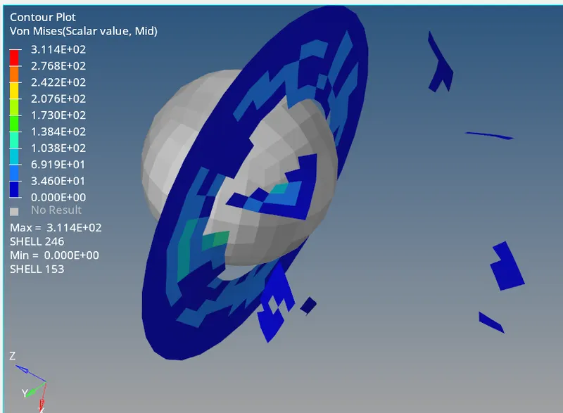
(FRAME 11)
In case4 since eps_p_max is zero, there is no deletion of the elements. Elements can go an infinite amount of deformation.
Since elements are deleted, there is less stress generated in case 3 compared to case4.
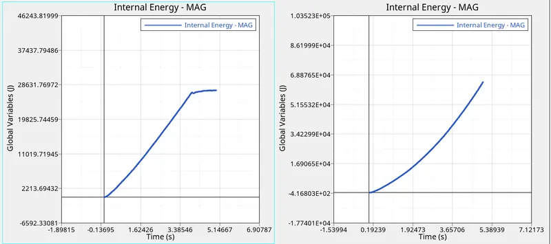
case3 and case4
In both cases there is an exponential increase of IE, but in case3 IE almost becomes constant once middle elements are deleted. After that, there is a very small increase in IE. In case 4, IE will increase until the defined runtime.
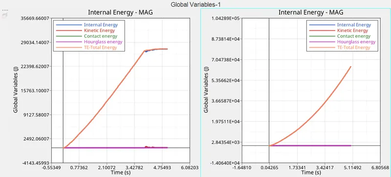
For kinetic energy plot, we see in case 4 it is almost constant and in case3 when there is deletion of elements, there is a sudden incraese in kinetic energy.
CASE 5:-Change Mat to Law_1
To define elasticity(Law1), we have to define three parameters:
`rho,E,nu`
Here density = 0.0027;
Youngs modulus= 71000;
poission ratio= 0.33;
unit system is g mm ms
Law 1 should not be used for parts undergoing large deformation.
For crash analysis, elastic material should be avoided.
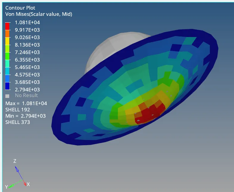
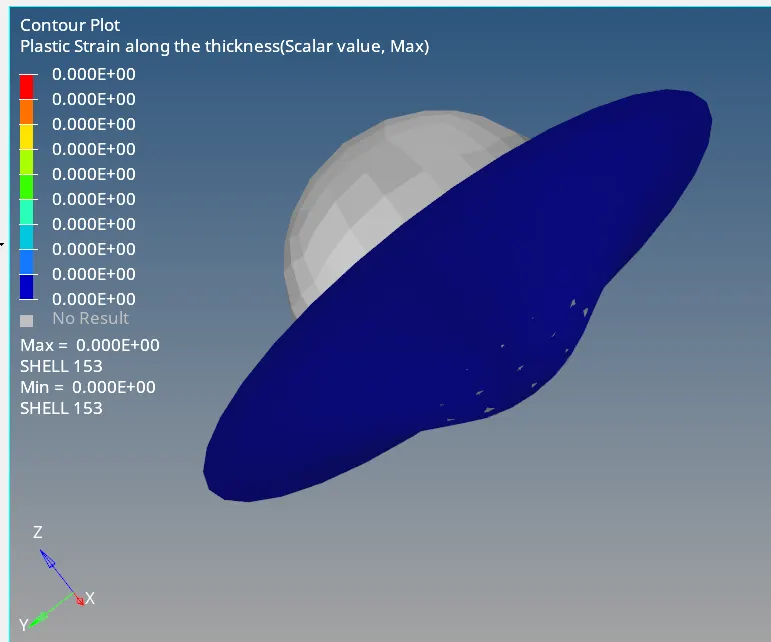
The elastic deformation is temporary and is fully recovered when the load is removed.that is why the plastic starin developed throughout the model is zero.
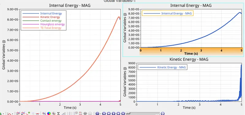
In ductile material, there is extensive deformation and energy absorption before fracture. This energy is stored in the form of internal energy which will be removed as the material goes to its original form.
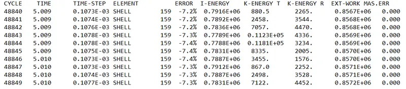
- the energy error is in acceptable limit.
CASE6: LAW27 (PLAS_BRIT)
This law combines an isotropic elastoplastic Johnson-Cook material model with an orthotropic brittle failure model. Material damage is accounted for prior to failure. Failure and damage occur only in tension. This law is applicable only for shells.
In this model, the material behaves as a linear-elastic material when the equivalent stress is lower than the plastic yield stress. For higher stress values, the material behavior is plastic and the stress is calculated using plastic strain and strain rate.
EPS_t1 >tensile plastic strain in material =0.14,stress will start to come down to zero.
EPS_m1=0.15>tensile stress comes down to zero at this plastic strain value.
EPS_f1=0.15> when plastic strain reaches this value, elements are deleted.
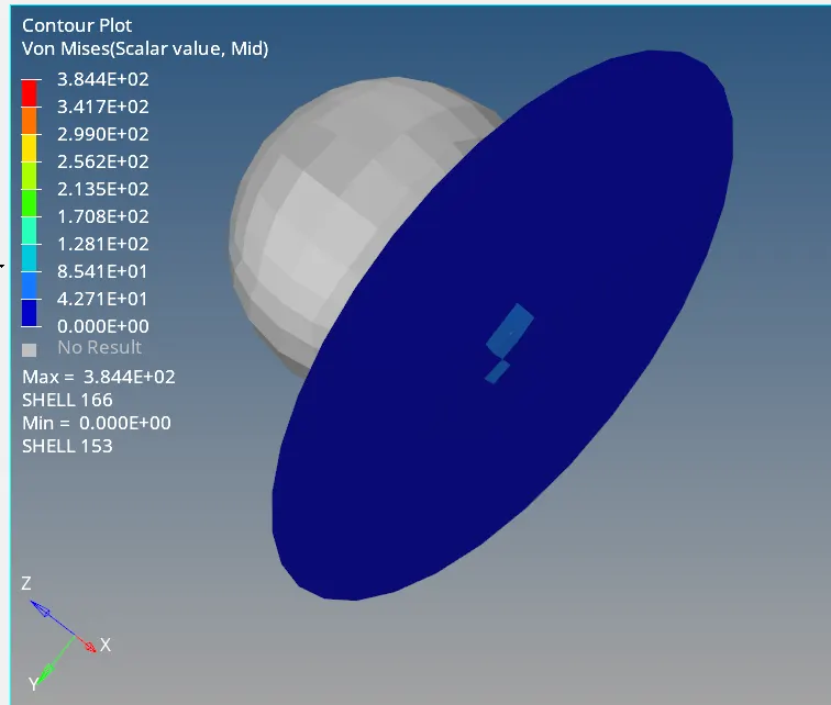
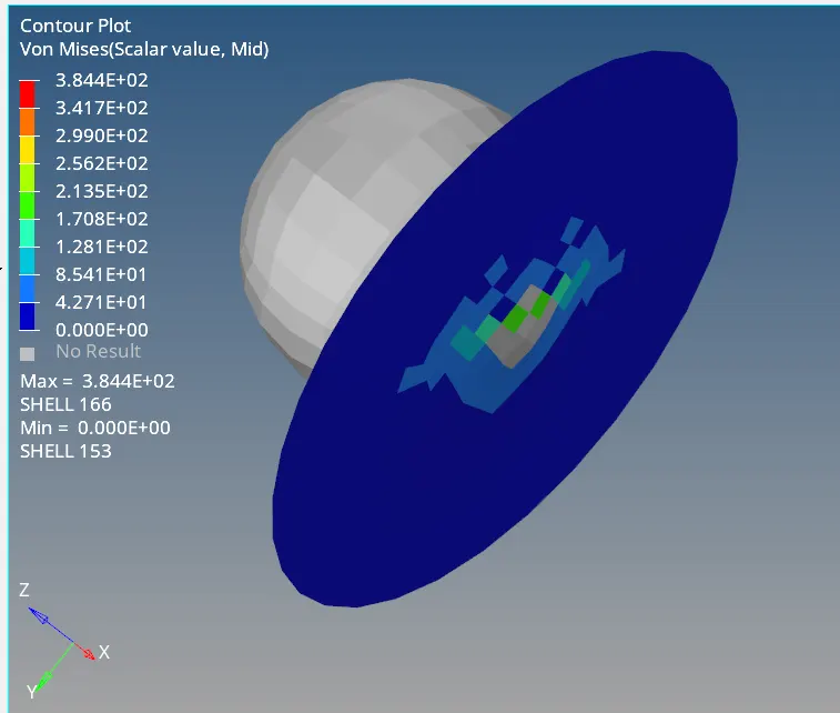
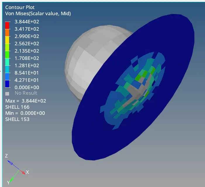
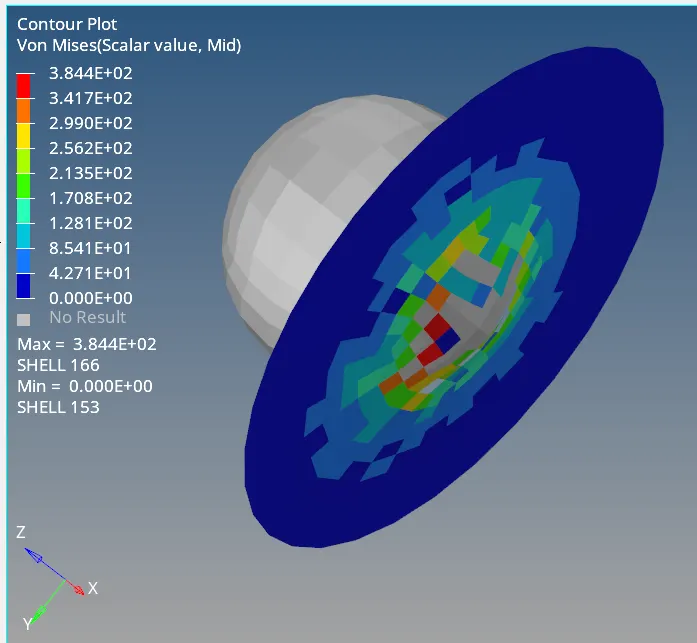
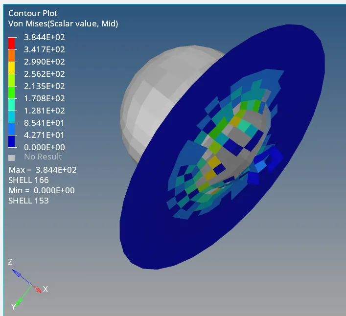
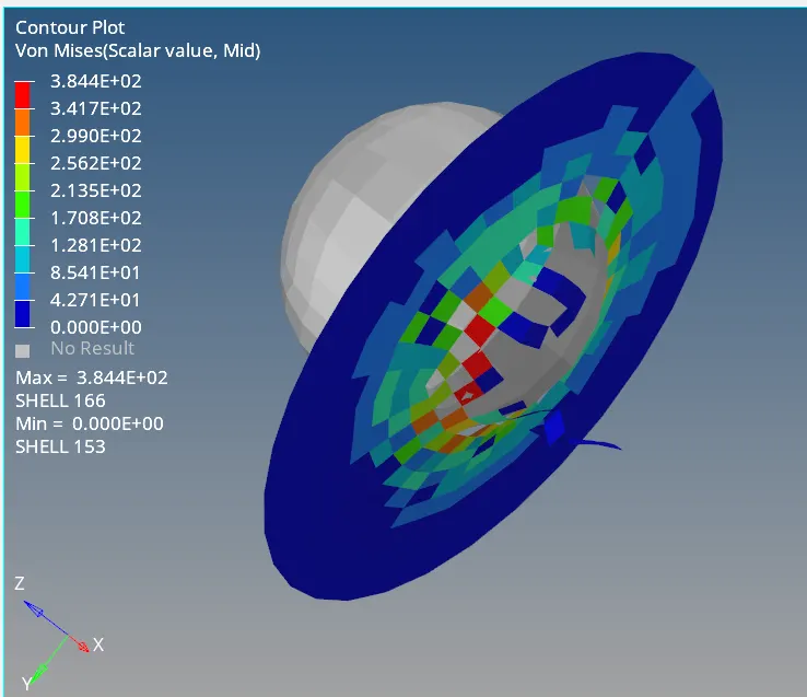
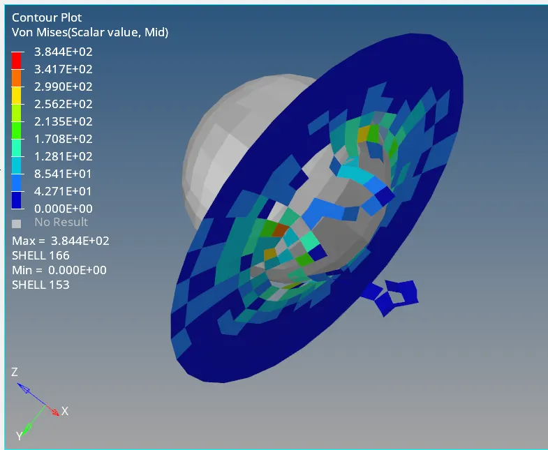
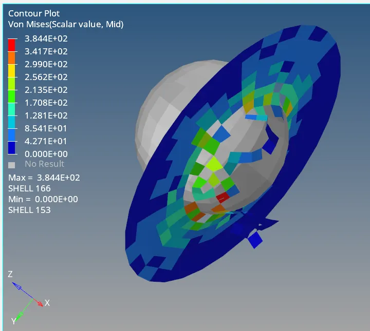
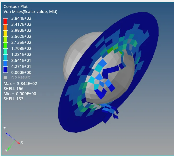
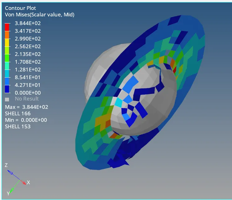
The material breaks once EPS_F1=0.151 and this breaking take place like breaking of glass.
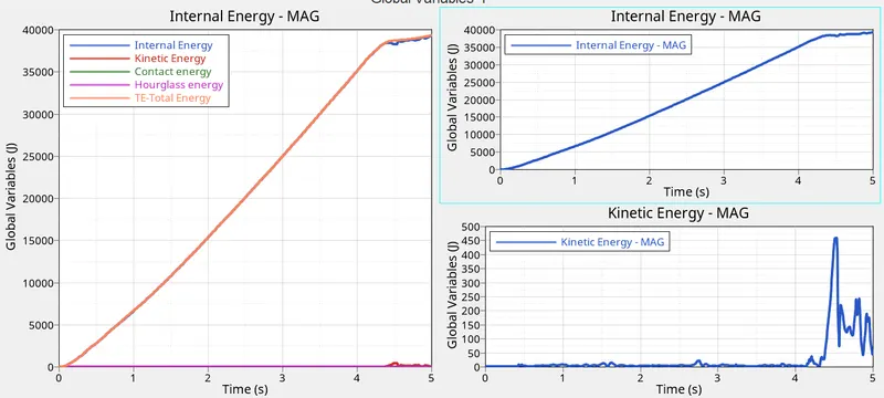
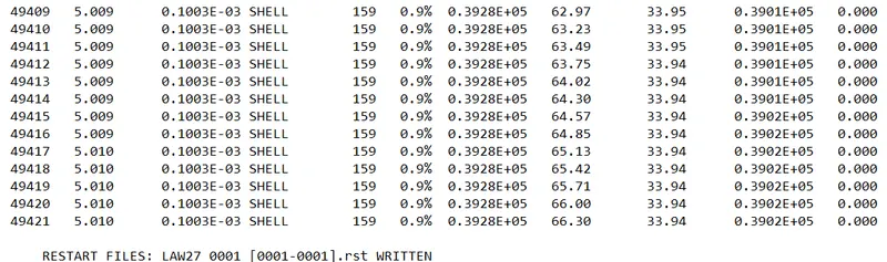
Total energy is almost equal to internal energy and HG energy is zero due to QEPH elements.
CASE7:LAW36(PLAS_TAB)
This law models an isotropic elastoplastic material using user-defined functions for the stress-strain curve (for example, stress vs. plastic strain) for different strain rates.
Available for both shell and brick elements.
Elastic portion is defined by Young's modulus, Poisson ratio, and density. We need this law because, in a real-time model, we don't know the actual yield point.
Before doing simulation, the material was created using a user-defined function.
Law 36 which is a isotropic elasto-plastic material using user-defined functions (curve).
create a curve with to apply in the material model N_funct.
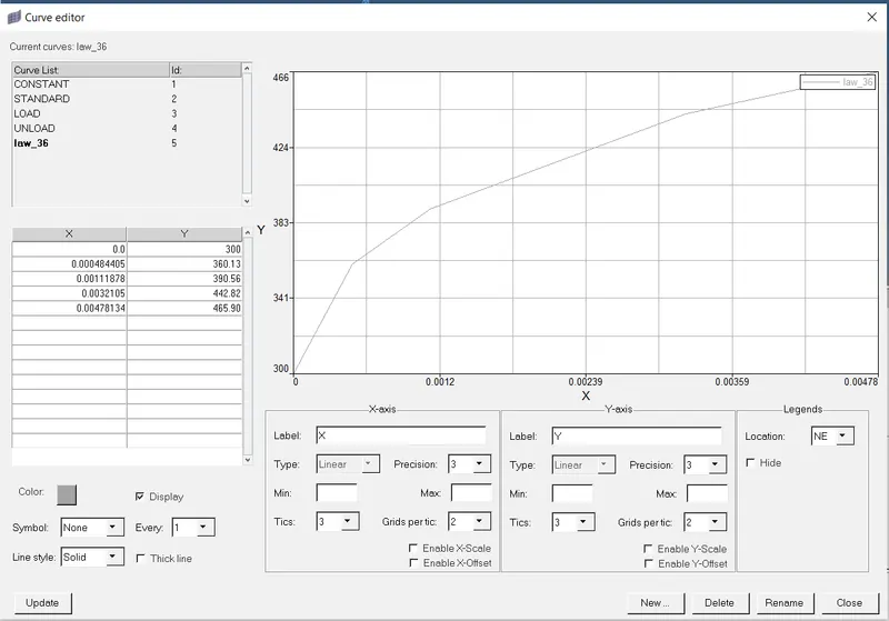

Material card selection and curve selection.
N_funct is Number of functions which can be between 1 and 100 depending on the requirments of the simulation.
Fscale default value is 1.
Once the EPS_p (plastic strain) reaches EPS_p_max , in one integration point, the element is deleted.
EPS_p_max:0.16> elements are deleted when strain reaches this value.
EPS_t:0.10 > plastic failure strain for tension, compression and shear.
EPS_m:0.11 >when tensile plastic strain in material is 0.11, stress in element become zero.
User-defined curve:
After assigning material, simulation is performed.
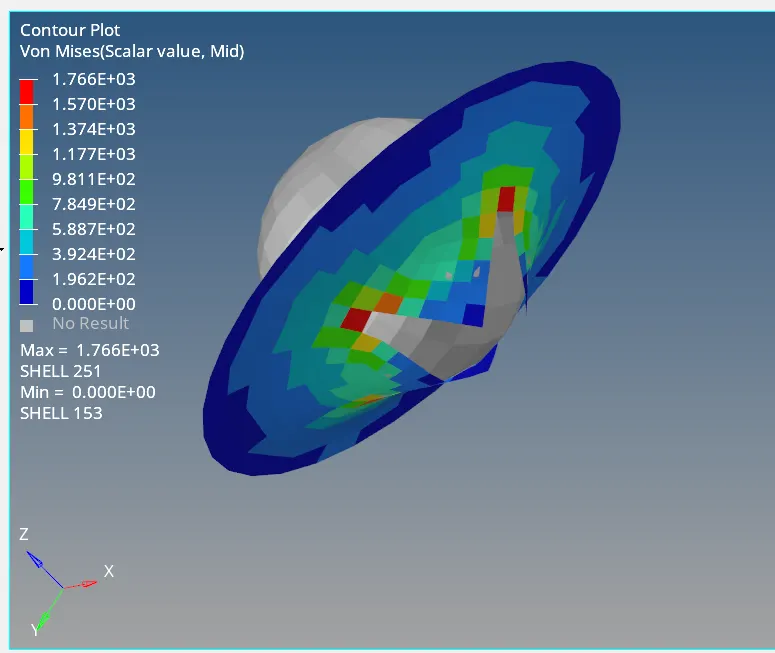
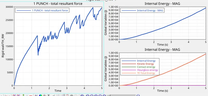
COMPARISON OF ALL SEVEN CASES
Here we studied seven cases and noticed animation, plotted internal energy, kinetic energy von mises stresses and total energy for all cases.
|
CASE |
MATERIAL MODEL/MATERIAL LAW |
NUMBER OF CYCLE |
ENERGY ERROR (%) |
MASS ERROR (%) |
SIMULATION TIME(SECONDS) |
REMARKS |
|
CASE1 |
FAIL JOHNSON, JOHNSON COOK MM(LAW2) |
49384 |
0.8 |
0 |
74.34 |
Elements are deleted without crack formation. |
|
CASE2 |
FAIL JOHNSON, JOHNSON COOK MM(LAW2) |
49407 |
3.7 |
0 |
109.79 |
First cracked are formed and then element deletion occurs. |
|
CASE3 |
JOHNSON COOK MATERIAL MODEL(LAW2) |
49405 |
0.8 |
0 |
107.91 |
eps_p_max was 0.151. The element was deleted when the plastic strain was 15% .material failed for the least amount of stress among all cases |
|
CASE4 |
JOHNSON COOK MATERIAL MODEL(LAW2) |
48737 |
3.0 |
0 |
127.60 |
eps_p_max was set to zero. No deletion of elements. |
|
CASE5 |
ELASTIC PLASTIC MODEL(LAW1) |
48850 |
-7.3 |
0 |
59.67 |
No deletion of elements but stress generated was very high. |
|
CASE6 |
PLAS_BRIT(LAW27) |
49422 |
0.9 |
0 |
144.18 |
Material was brittle and failure occurred when EPS_f1=0.15 |
|
CASE7 |
PLAS_TAB(LAW36) |
52032 |
0.9 |
0 |
63.64 |
Isotropic elastoplastic material. Elements deleted when EPS_p_max=0.16 |
CONCLUSION:
RADIOSS material library contains several distinct material laws.
Selecting a correct material model plays a very important role in simulation. Selecting the wrong material model and doing simulation will also give result but it will not represent the actual situation.
Law 1 is used to model purely elastic materials or materials that remain in the elastic range. To model this we require Poisson's ratio and Young's modulus. This law represents a linear relationship between stress and strain.
Law 2: In this law, the material behaves as linear elastic when equivalent stress is lower than the yield stress. For a higher value of stress, the material behaves like plastic. Failure can be captured better with the help of an optional Fail_Johnson card.
Law 27: Used for brittle materials.
Law 36:The elastic-plastic behavior of isotropic material is modeled with user-defined functions. The stress-strain curve is modeled using E and Poisson's ratio. The hardening behavior of the material is defined in the function of plastic strain for a given strain rate.