Assignment 4
OBJECTIVE - To analyse different type of material properties and compare the result of 7 cases with the given material properties and conditions.
PROCEDURE -
CASE 1 - Law 2 - M2 plas johns zeril - Elasto-plastic (johnson- cook material) :
It is an elasto- plastic material model that includes strain rate and temperature effect with true stress and strain output but we neglect temperature and heat change during crash test.
Failure of element happen when 1 integration point reaches EPS_MAX value.
so we import the Failure_johnson_0000.rad. file where input parameter are Eps_P_max, a,b,c,n are already filled.
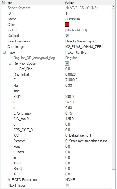
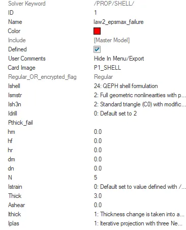
As per input parameter now we can run the file as it is
After radioss run first we open FAilure_johnson_0001.rad in notepad and check energy error and mass error.
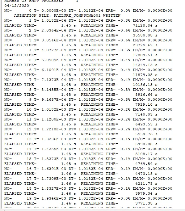
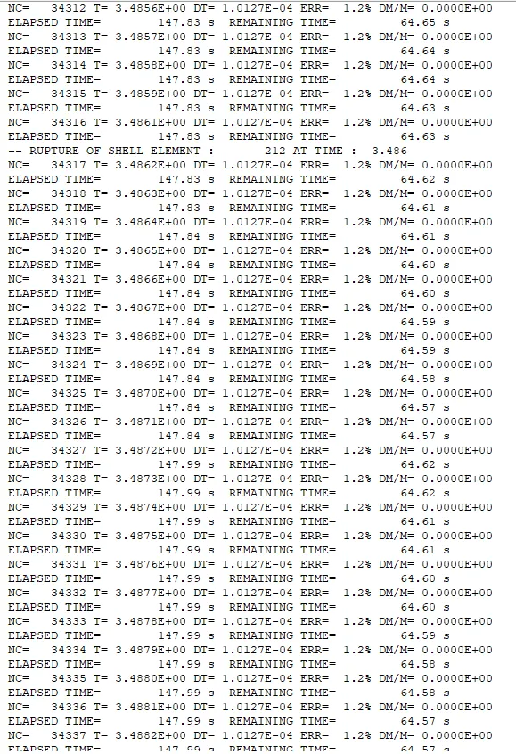
Here energy error in the basic simulation case is min. - 0.6% to max. 1.2% .
energy error is accepted upto 15%
mass error - 0%
simulation time - 5.01ms
total number of cycle - 49379
now move to hyperview for run the simulation select h3d file and open .
click contour and resultant type as displacement and click on apply
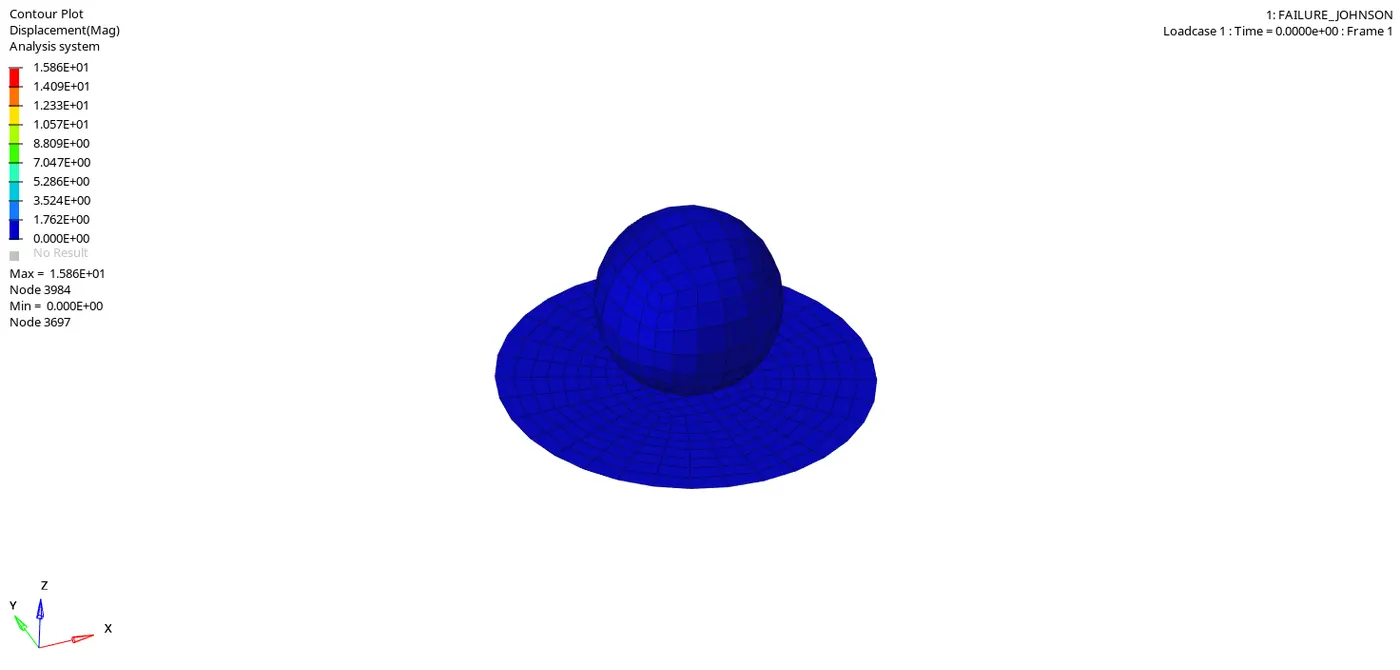
Here we found a maximum displacement at node 3984 - 15.86
now instead of displacement select vonmises stress and click apply.
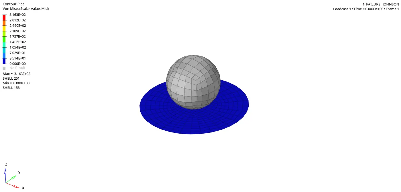
Here we found a maximum vonmises stress at node 251 which is 316.
In this we can observed that the circular plate is going to fail for the material because when the plate is stressed by rigid body it moves from elastic limit to plastic limit. here failure takes place because of the failure limit exceeds the EPS_MAX value
now next move to hypergraph 2D for plot the graph. Load the T01 file and select X type - time , Y type - Global variable, Y request - Kinetic energy, internal energy, contact energy, hourglass energy or total energy.
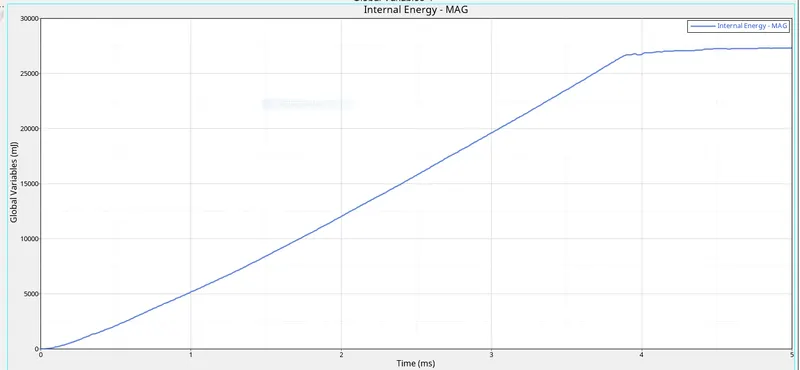
here internal energy increases with the increase of time because during collosion energy is dissipiate in the form of heat which increase the internal energy.
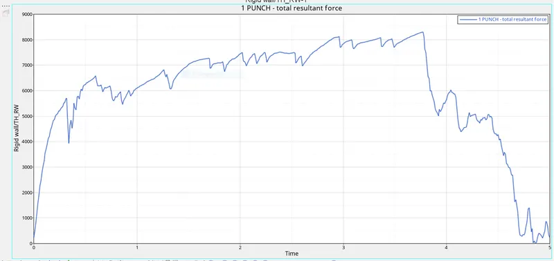
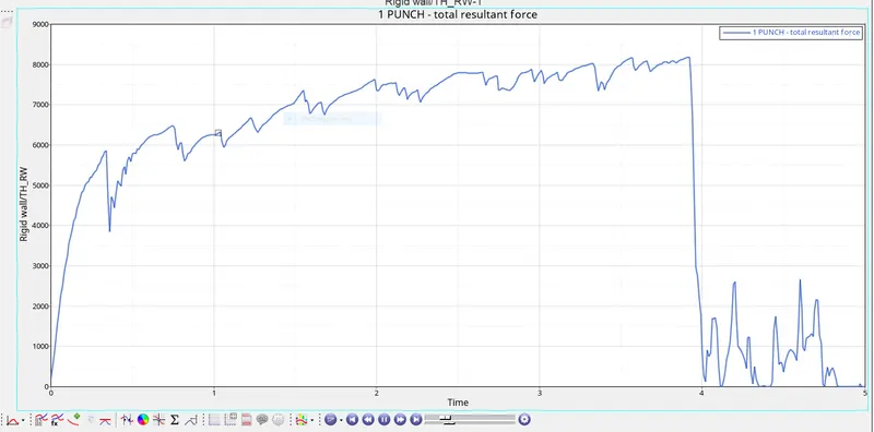
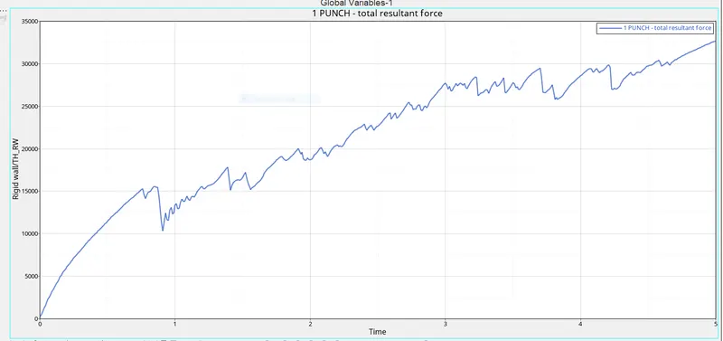
now plot the resultant force graph ,for this we go to Rigid wall - 4 rigidwall - Resultant force.
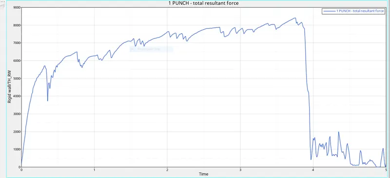
In rigid wall graph it can be seen that element are deleted perodically as when the reach to EPS_P_MAX and in around 4ms there may be sudden drop of force because at that time element resisting the wall get deleted in huge amount .
CASE 2 - Law 2 with changes of properties in Fail _johnson and crack visualization -
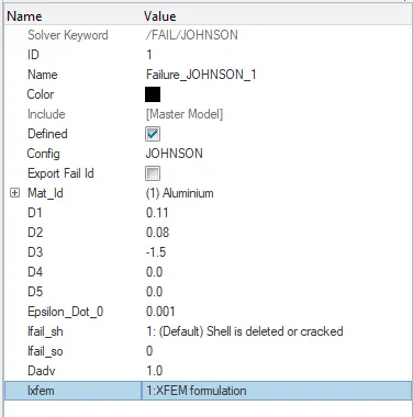
In failure johnson card changes the ifail_sh=1, dadv=1 and Ixfem=1 and run the model using radioss, the material card and properties card are as follows by previous step
Now run the model in radioss and check the energy and mass error.
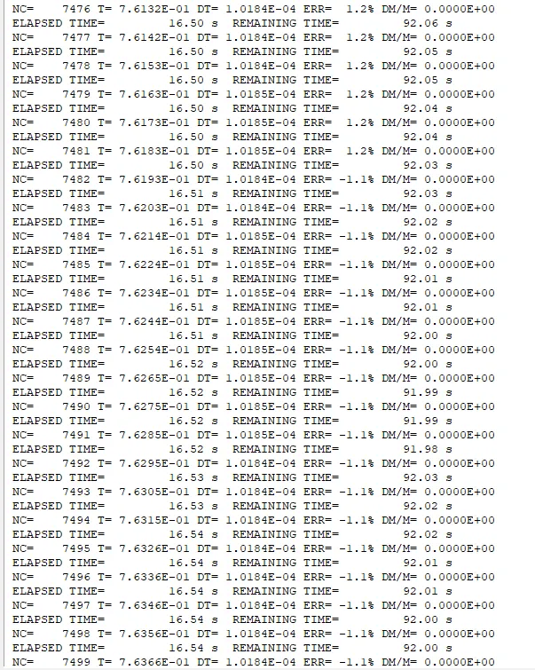
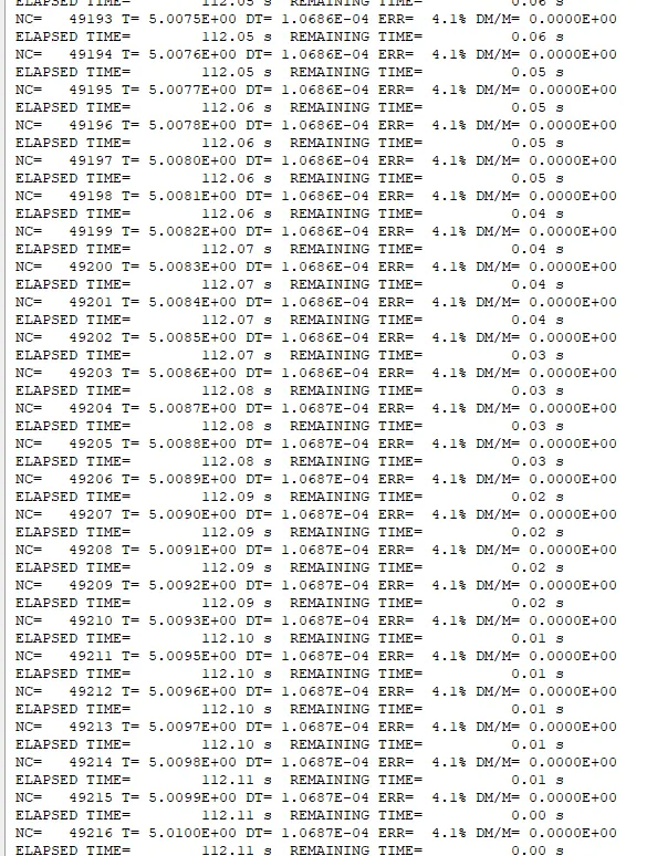
Here energy error in the basic simulation case is min. - 1% to max. 4.1% .
energy error is accepted upto 15%
mass error - 0%
simulation time - 5.01ms
total number of cycle - 49216
now move to hyperview for run the simulation select h3d file and open .
click contour and resultant type as displacement and click on apply
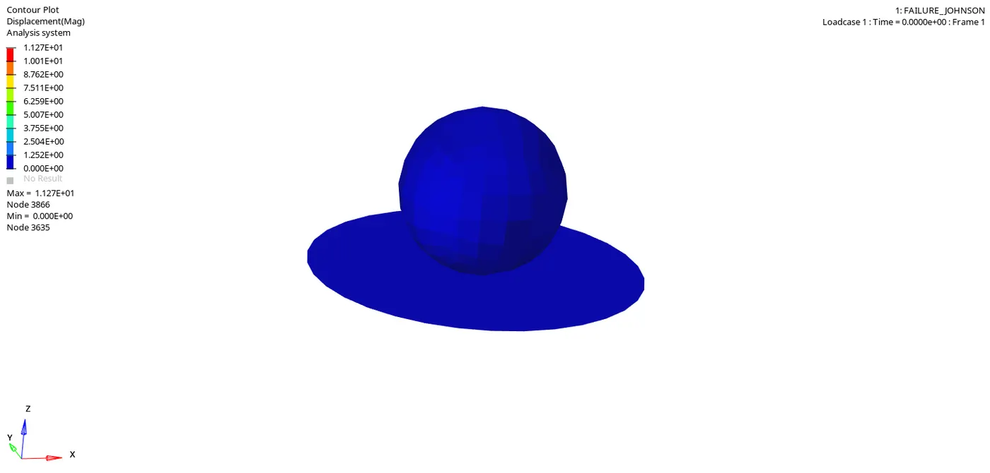
Here we found a maximum displacement at node 3866 - 11.27
now instead of displacement select vonmises stress and click apply.
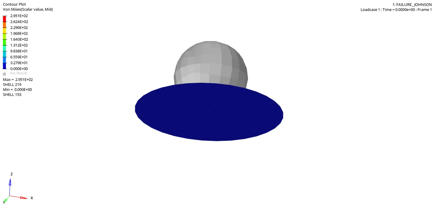
Here we found a maximum vonmises stress at node 219 which is 295.
The element over here are getting cracked as it is very poor element formulation property.
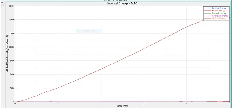
now next move to hypergraph 2D for plot the graph. Load the T01 file and select X type - time , Y type - Global variable, Y request - Kinetic energy, internal energy, contact energy, hourglass energy or total energy.
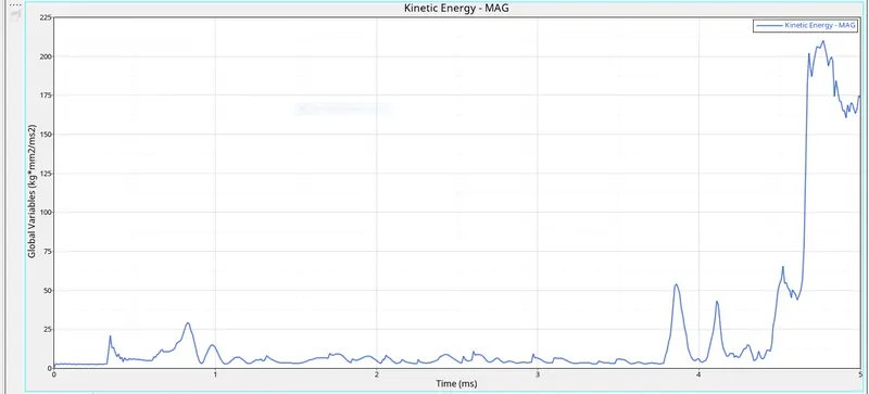
so, Kinetic energy goes zigzag way not to much deflection at starting because the element get cracked in smoothing way and at the end there may some spike because the more element get deleted at that time.
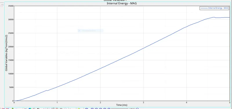
So ,Internal energy increases linearly because there may be some absorption of kinetic energy during impact .
CASE 3 - Delete fail johnson card and run the model -
so in this case the material is same as the electroplastic but here the failure model card has been removed to findout different results.
here the plastic_johns_zeril has deleted and the material card and property card properties are same as previous.
Now run the model in radioss and check the energy and mass error.
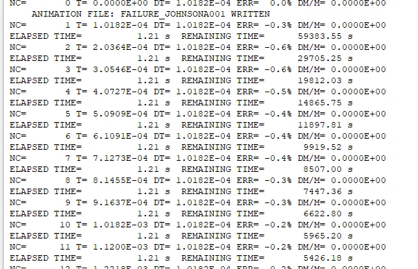
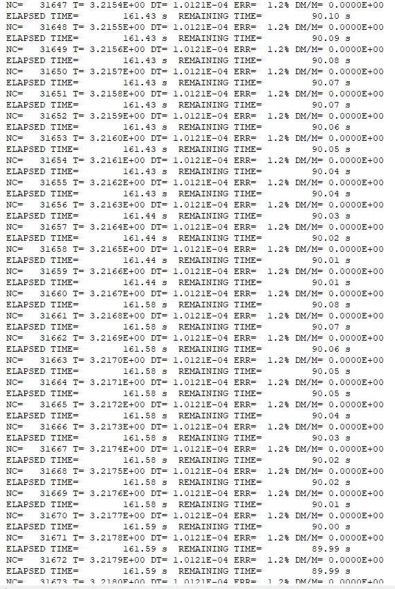
Here energy error in the basic simulation case is min. - 0.6% to max. 1.2% .
energy error is accepted upto 15%
mass error - 0%
simulation time - 5.01ms
total number of cycle - 49407
now move to hyperview for run the simulation select h3d file and open .
click contour and resultant type as displacement and click on apply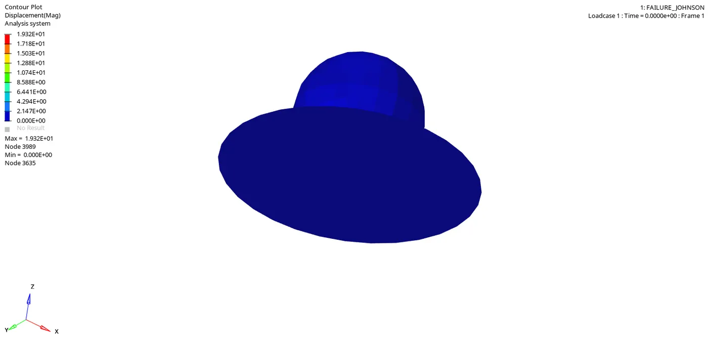
Here we found a maximum displacement at node 3989 - 19.32
now instead of displacement select vonmises stress and click apply.
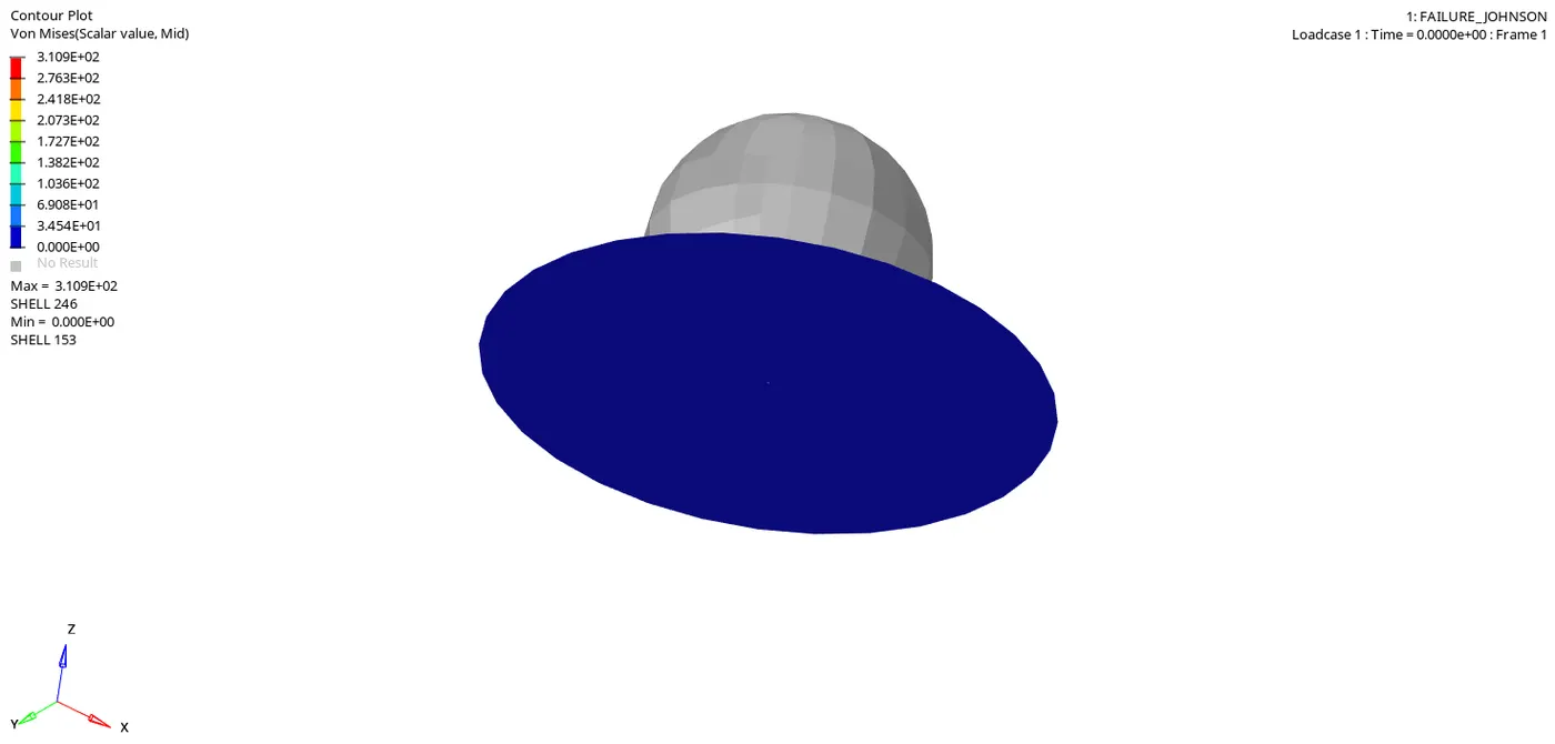
Here we found a maximum vonmises stress at node 246 which is 311
now next move to hypergraph 2D for plot the graph. Load the T01 file and select X type - time , Y type - Global variable, Y request - Kinetic energy, internal energy, contact energy, hourglass energy or total energy.
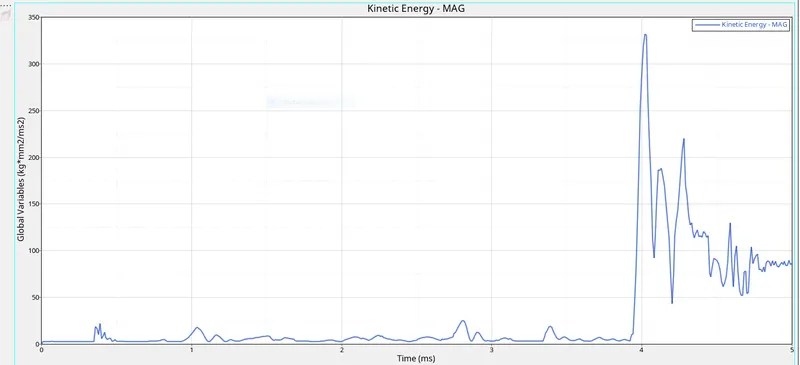
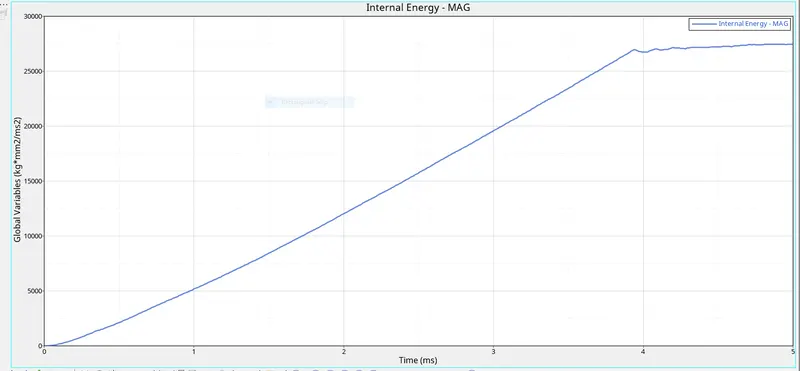
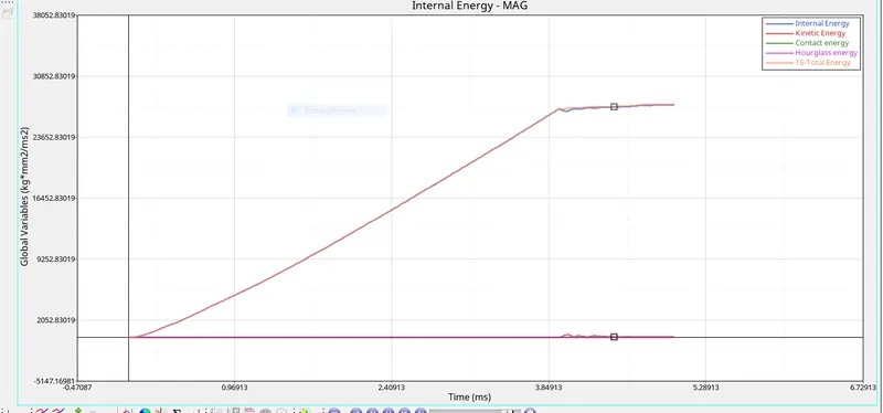
now plot the resultant force graph ,for this we go to Rigid wall - 4 rigidwall - Resultant force.
CASE 4 - Law 2 with the deletion of EPS_P_MAX VALUE -
In this case ,the Eps_p_max which is defined as the Plastic Strain beyond this will cause element deletion is deleted, where default value is set.
This make the material behave electroplastic such that This option is to use the failure criteria based on the maximum principal strain. When the principal strain of the model reaches Eps_f value (maximum tensile failure strain), the element is deleted.
This material model provides an elastic-plastic material option that allows stress vs. strain curve input and strain rate dependency. Failure is based on effective plastic strain or the major principal in-plane strain component.
For EPS_t is the tensile failure strain at which stress starts to reduce.
For EPS_m, when the principal strain is more than EPS_m the stress is reduced to 0,but the element is not deleted.
For EPS_f, failure criteria based on the maximum principal strain. The element is deleted once when the principal strain of the model reaches Eps_f value.
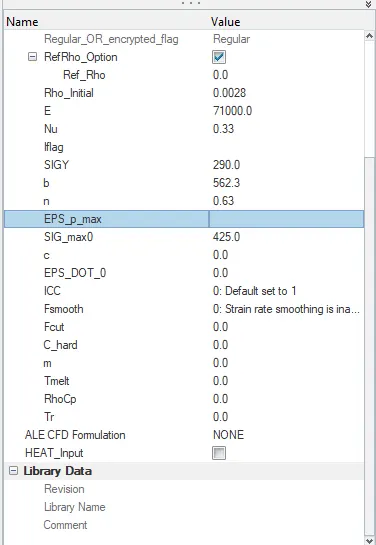
the material card and property card properties are same as previous.
Now run the model in radioss and check the energy and mass error.
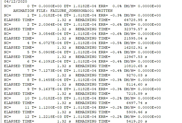
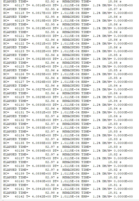
Here energy error in the basic simulation case is min. - 0.6% to max. 1.2% .
energy error is accepted upto 15%
mass error - 0%
simulation time - 5.01ms
total number of cycle - 49303
now move to hyperview for run the simulation select h3d file and open .
click contour and resultant type as displacement and click on apply.
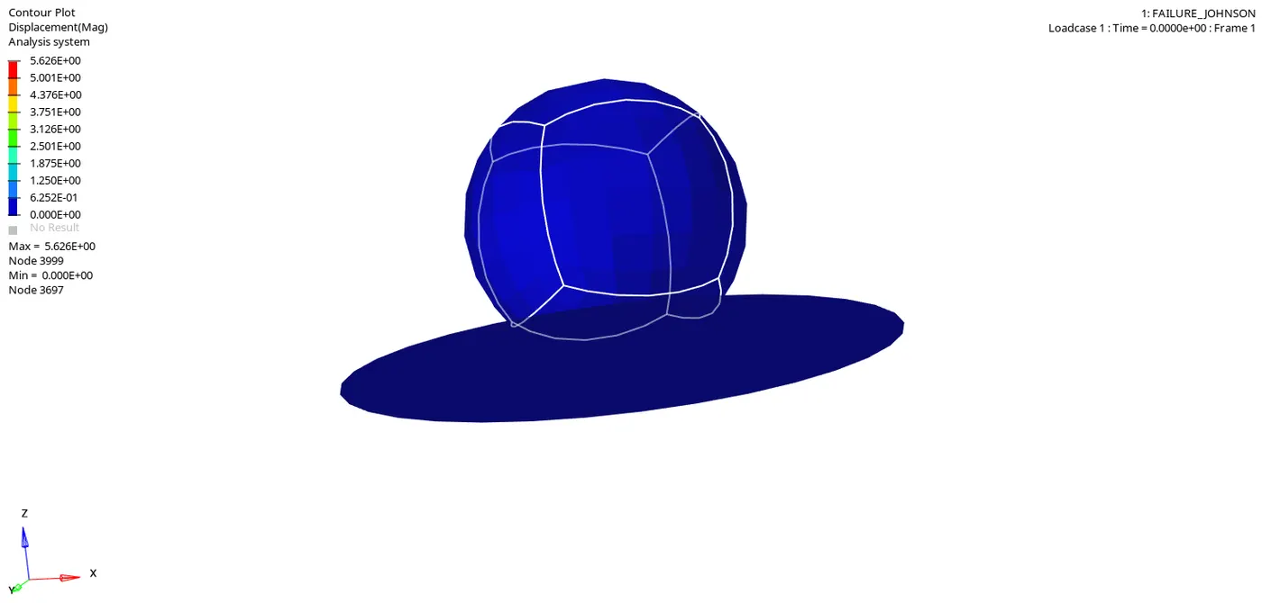
Here we found a maximum displacement at node 3999 - 5.62
now instead of displacement select vonmises stress and click apply.
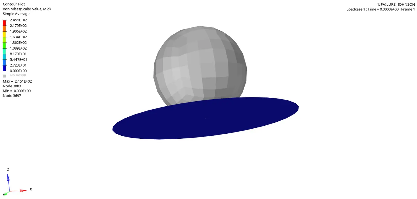
Here we found a maximum vonmises stress at node 3803 which is 245.
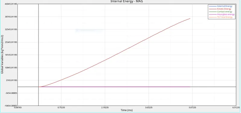
now next move to hypergraph 2D for plot the graph. Load the T01 file and select X type - time , Y type - Global variable, Y request - Kinetic energy, internal energy, contact energy, hourglass energy or total energy.
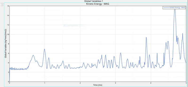
here kinetic energy is not periodically smooth because the element of plate is showing plastic strain before deletion.
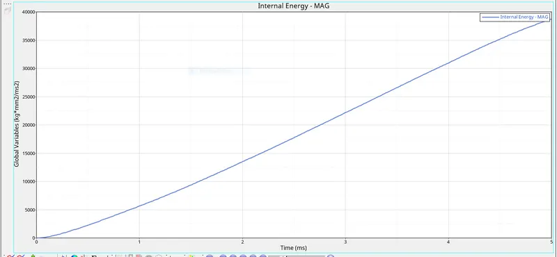
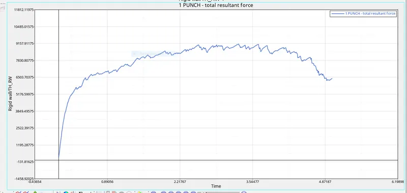
now plot the resultant force graph ,for this we go to Rigid wall - 4 rigidwall - Resultant force.
CASE 5 - Law 1 Elastic material -
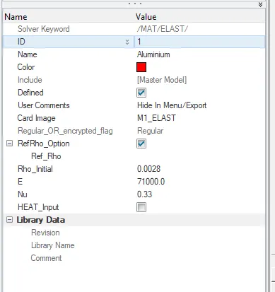
Here convert the material model into Law 1 elastic with same density, E, nu and run the model.
In this case material is elastic which behaves linear follow hooks law upto elastic limit , when material undergoes a plastic stage throughout the strain. here element are following linear elastic curve they will keep on expanding as the load progress and return back to its original shape . its good for component that they never cross elastic zone but in crash application not a good idea
Now run the model in radioss and check the energy and mass error.
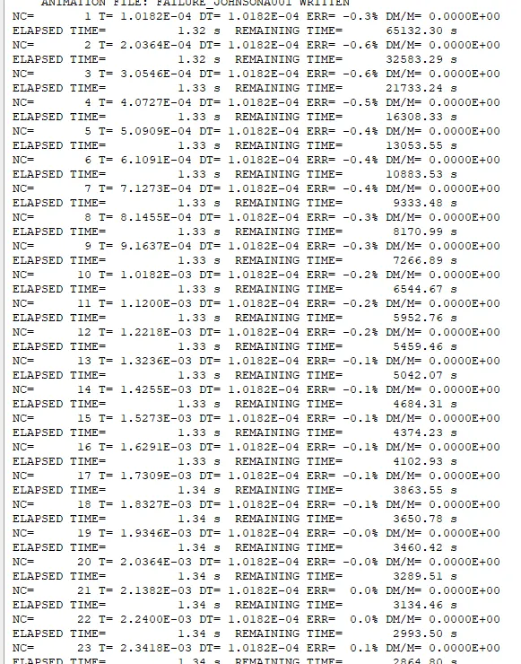
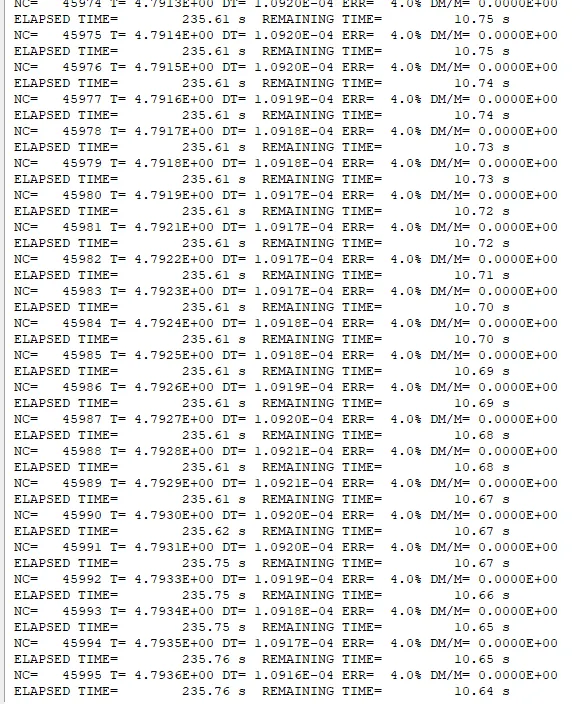
Here energy error in the basic simulation case is min. - 0.6% to max. 4% .
energy error is accepted upto 15%
mass error - 0%
simulation time - 5.01ms
total number of cycle - 47968
now move to hyperview for run the simulation select h3d file and open .
click contour and resultant type as displacement and click on apply
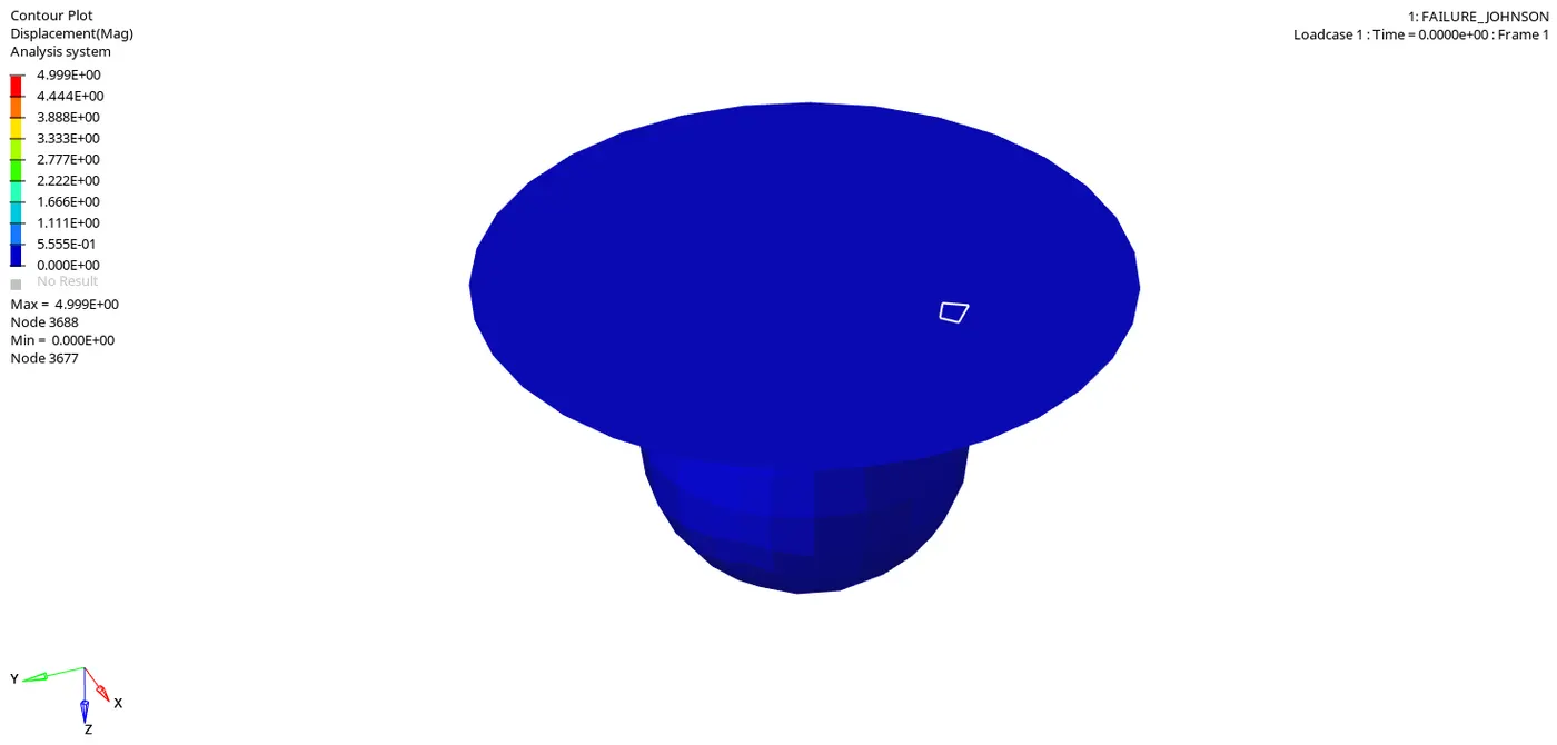
Here we found a maximum displacement at node 3688 - 4.9
now instead of displacement select vonmises stress and click apply.
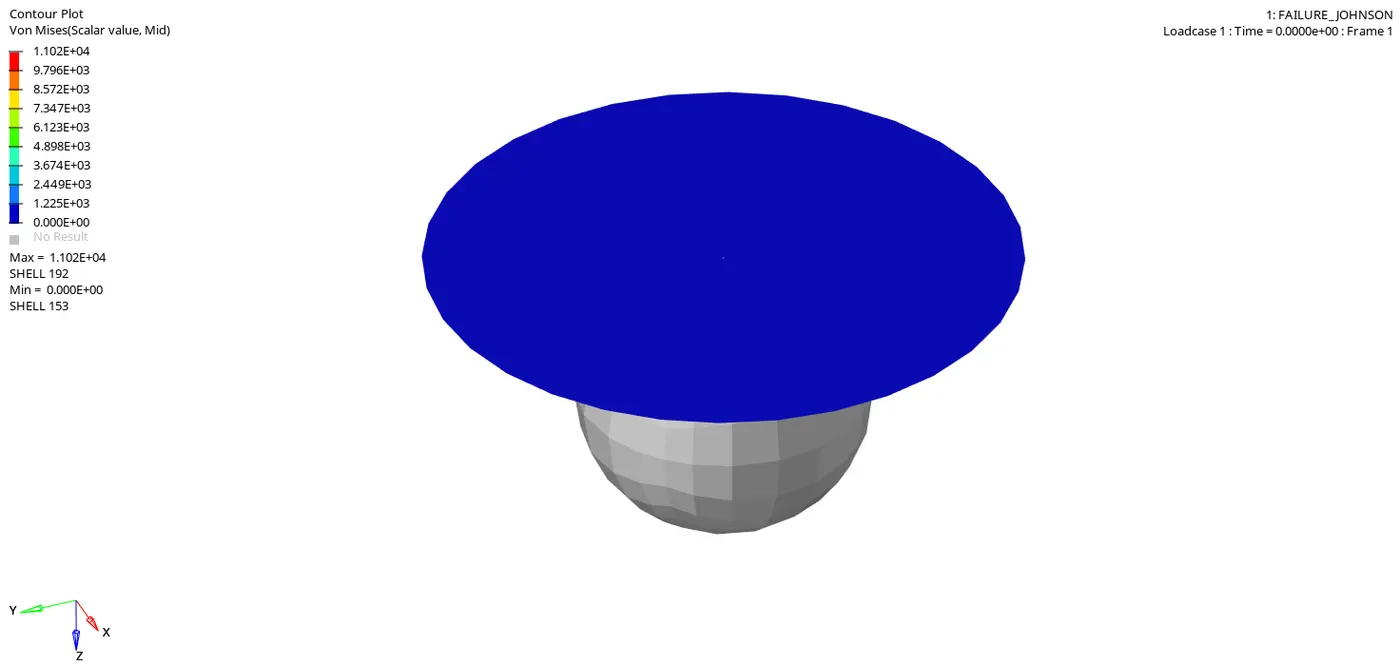
Here we found a maximum vonmises stress at node 192 which is 1.102E+04
now next move to hypergraph 2D for plot the graph. Load the T01 file and select X type - time , Y type - Global variable, Y request - Kinetic energy, internal energy, contact energy, hourglass energy or total energy.
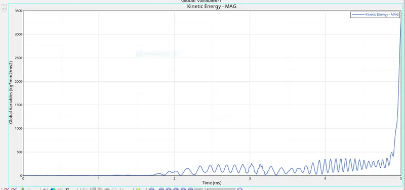
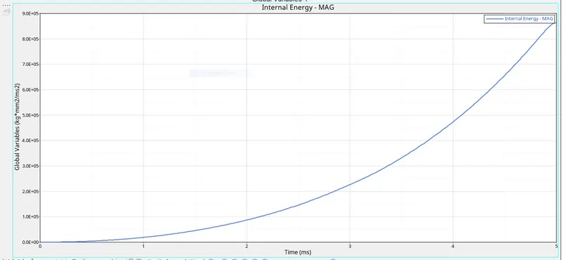
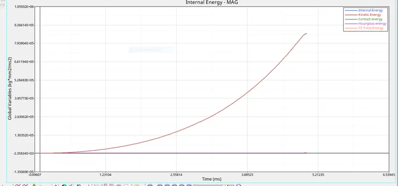
The kinetic energy gradually increase as the plate get stiched to the maximum stress.
The internal energy increases linearly due to the absorption of kinetic energy during impact.
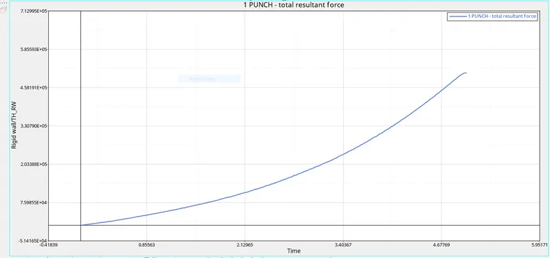
now plot the resultant force graph ,for this we go to Rigid wall - 4 rigidwall - Resultant force.
CASE 6 - LAW 27 - PLAST_BRIT MATERIAL -
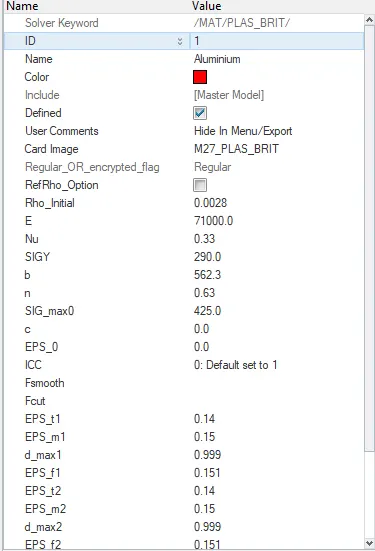
A Plast_brit material law 27 is used with given values its consist of parameters definining the brittle nature of material. the shell properties were change to recommended.
Now run the model in radioss and check the energy and mass error.
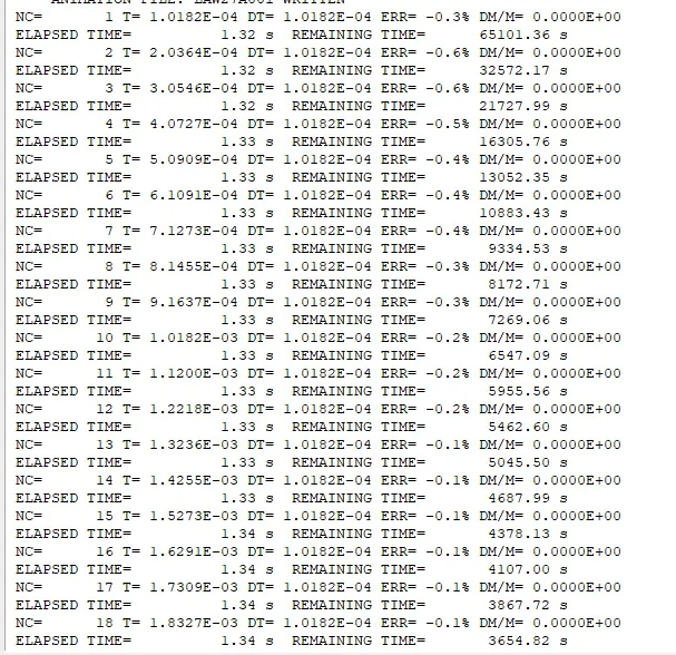
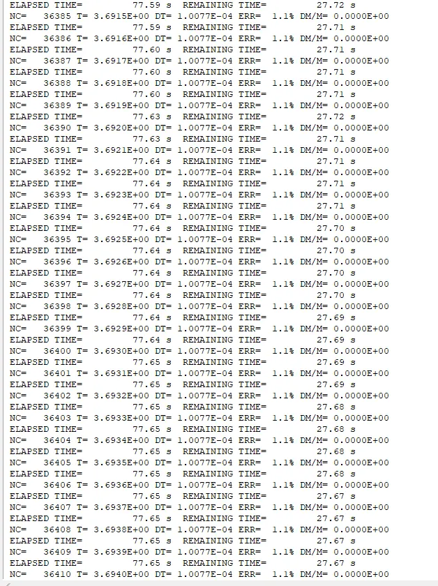
Here energy error in the basic simulation case is min. - 0.6% to max. 1.1% .
energy error is accepted upto 15%
mass error - 0%
simulation time - 5.01ms
total number of cycle - 49507
now move to hyperview for run the simulation select h3d file and open .
click contour and resultant type as displacement and click on apply
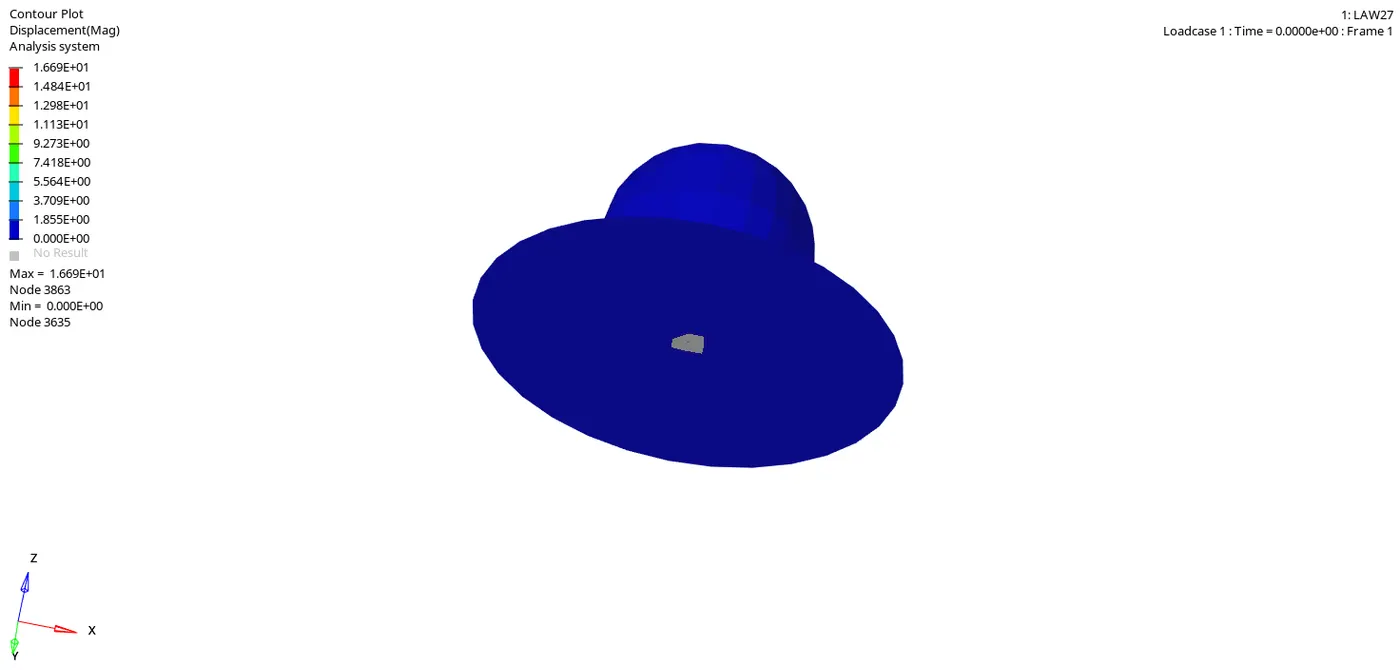
Here we found a maximum displacement at node 3863 - 16.69
now instead of displacement select vonmises stress and click apply.
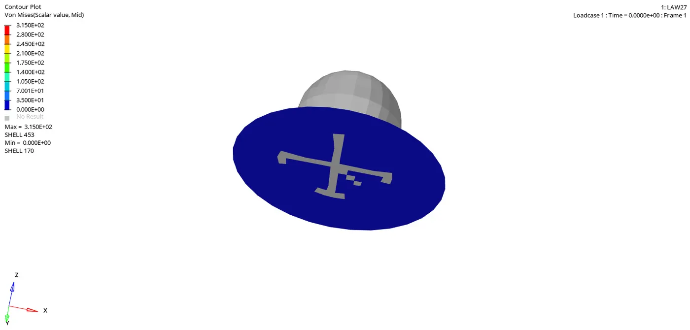
Here we found a maximum vonmises stress at node 453 which is 315
now next move to hypergraph 2D for plot the graph. Load the T01 file and select X type - time , Y type - Global variable, Y request - Kinetic energy, internal energy, contact energy, hourglass energy or total energy.
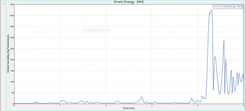
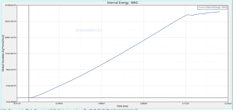
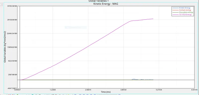
now plot the resultant force graph ,for this we go to Rigid wall - 4 rigidwall - Resultant force.
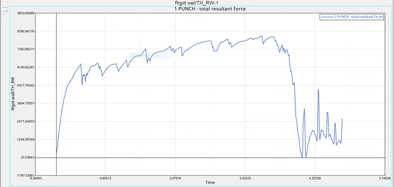
CASE 7 - Law 36 - Plas_tab material -
Convert the card to law 36 which is elastic plastic tabulated
In this case material model, the input parameter were we previous discuss about eps_p_max, eps_m and EPS_t are defined default and we can add user defined true stress - strain curves from actual test lab to get very accurate result from the simulation.
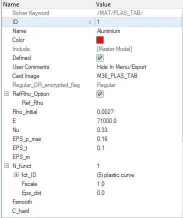
Now run the model in radioss and check the energy and mass error.
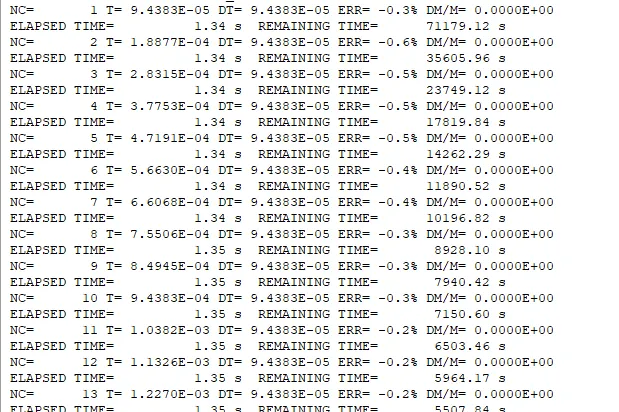
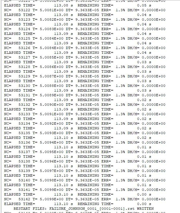
Here energy error in the basic simulation case is min. - 0.6% to max. 1.3% .
energy error is accepted upto 15%
mass error - 0%
simulation time - 5.01ms
total number of cycle - 53142
now move to hyperview for run the simulation select h3d file and open .
click contour and resultant type as displacement and click on apply
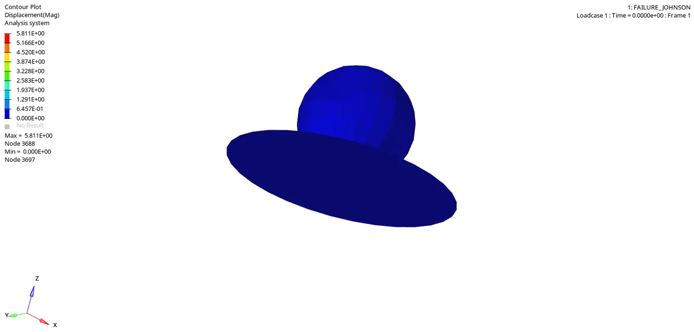
Here we found a maximum displacement at node 3688 - 5.8
now instead of displacement select vonmises stress and click apply.
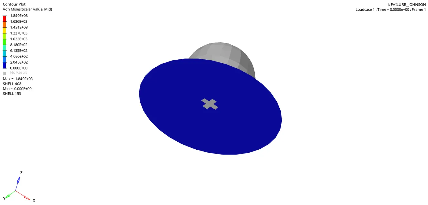
Here we found a maximum vonmises stress which is 1840.
Here the plate didnot exploded it rupture due to shearng.
now next move to hypergraph 2D for plot the graph. Load the T01 file and select X type - time , Y type - Global variable, Y request - Kinetic energy, internal energy, contact energy, hourglass energy or total energy.
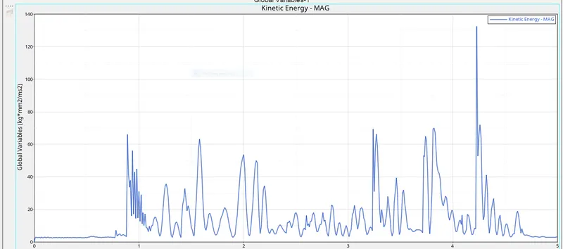
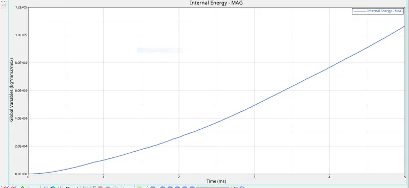
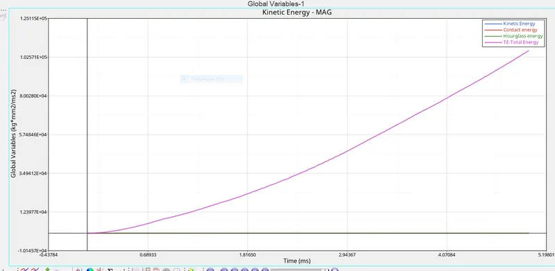
Here internal energy of the plate increase linearly due to the absorption of some kinetic energy when sphere strike with plate. and there may be some spike in kinetic energy to due to deletion of an element.
now plot the resultant force graph ,for this we go to Rigid wall - 4 rigidwall - Resultant force.
The distribution of stresses shows the plastic nature of the material when compared to elastic material.
The input curve initially which goes linear afterward high stress and strain value are recorded.
Comparison of case with total no. of cycle, energy or mass error .
Case total no. of cycle energy error mass error simulation time (ms)
1 49379 1.2% 0% 5.01
2 49216 4.1% 0% 5.01
3 49407 1.2% 0% 5.01
4 49303 1.2% 0% 5.01
5 47968 4.0% 0% 5.01
6 49507 1.1% 0% 5.01
7 53142 1.3% 0% 5.01
so since we used QEPH shell formulation there is no hourglass energy.
Summary -
Case 1 - Element are deleted once the plastic strain on one integration point reaches 15.1% of total plastic strain
case 2 - Element are cracked when the strain reaches 15% of plastic strain
case 3 - Element are deleted once the plastic strain on one integration point reaches 15.1% of total plastic strain
case 4 - the element get deleted when the plate gets the maximum stress impact .
case 5 - There is no rupture of failure model associated with this elastic case, so no element deletion .
case 6 - the element starting to fail when the Eps_f value reaches one integration point.
case 7 - Element are deleted once the plastic strain on one integration point reaches 15.1% of total plastic strain .
CONCLUSION - By changing one parameter out of so many parameter your whole result can change , so studying material behaviour carefully and having given right input value can give you accurate results.