Assignment 4
AIM:
To run the simulations for 7 different cases for "RUPTURE PLATE", provided with appropriate given data.
OBJECTIVE:
Compare all the 7 different cases according to:
- Total number of cycles, Energy error, mass error and simulation time.
- Notice the animation of all 7 and describe the animations in brief on the basis of whether the elements are being deleted or cracked.
- Plot energies and notice any difference.
- Based on all the results, which case would represent the on-field scenario.
- Prepare a ppt/docx and list down case by case result and your conclusion as to why the failure happened.
PROCEDURE:
CASE-1
RUNNING THE GIVEN MODEL AS IT IS BY IMPORTING "FAILURE_JOHNSON_0000.rad" TO SOLVER DECK:
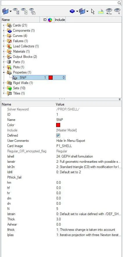
DEFAULT PROPERTY CARD IMAGE:
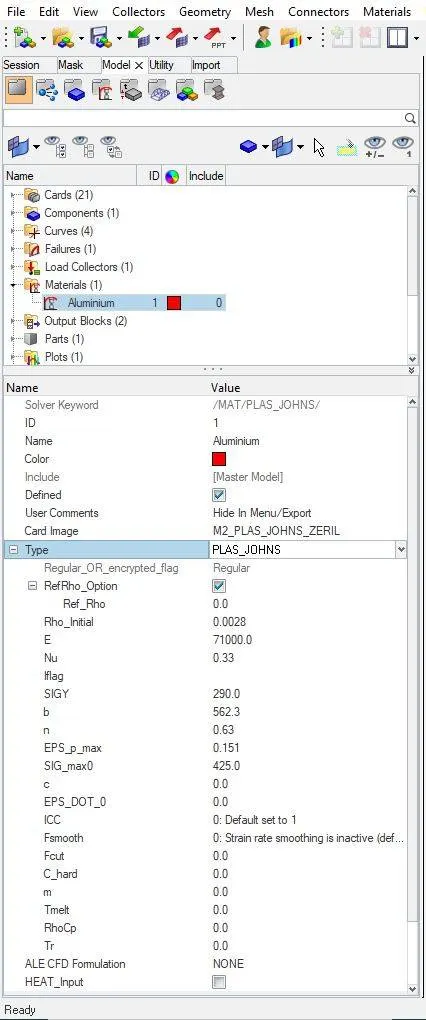
DEFAULT MATERIAL CARD IMAGE: HERE "M2_PLAS_JOHNS" HAS BEEN USED AS MATERIAL CARD AS SHOWN BELOW:
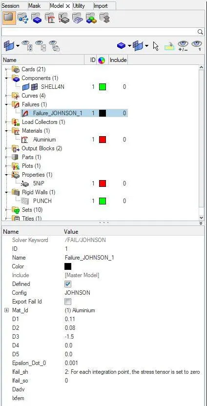
DEFAULT FAILURE CARD IMAGE:
WE HAVE TO NOW START THE SIMULATION BY SAVING IT AS PER THE NAME SUGGESTED, AS SHOWN BELOW:

RESULTS OF CASE-1 :
ERRORS ARE AS SHOWN BELOW:
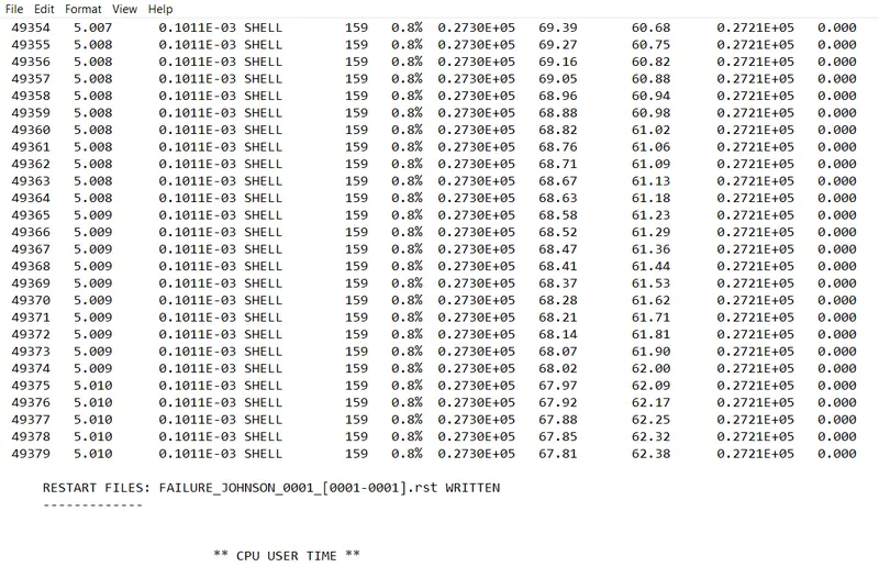
FROM THE ABOVE RESULT WE GET:
ENERGY ERROR = 0.8%
MASS ERROR = 0
NUMBER OF CYCLES = 49380
TOTAL ELAPSED TIME = 94.78 sec
WE HAVE TO OPEN "h3d" FILE IN HYPERVIEW TO SEE THE ANIMATION AS SHOWN BELOW:
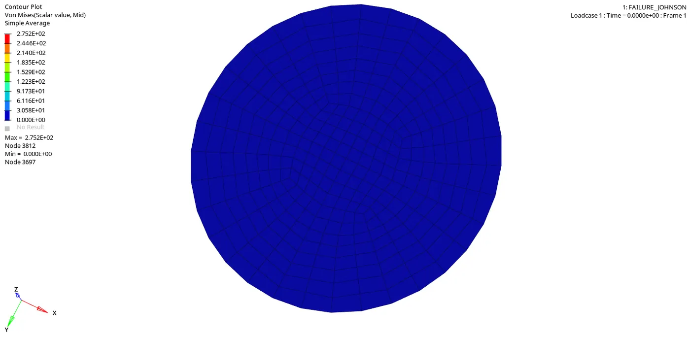
The "Maximum pressure" at which the "Rupture Plate" is getting failed is at 2.752E+02, here at this point the rupture plate experiences the "Maximum Plastic strain" and "Rupture Plate" will fail at this point.
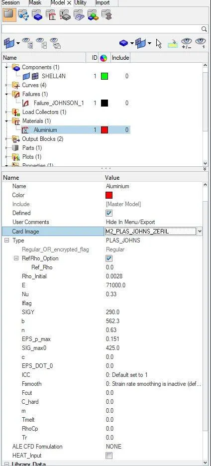
In material card "SIG_max0" is defined as 425pa, so here as we can see in the above simulation, the "Rupture Plate" is failing at pressure 275.2pa, so this value is below the defined material card value, so we can conclude that the "RUPTURE PLATE" is failing because of the "PRE DEFINED" values of "EPS_P_max" and "SIG_max0".
NOW WE HAVE TO OPEN A "TO1" FILE IN "HYPERGRAPH" TO PLOT ALL THE ENERGIES AS SHOWN BELOW:
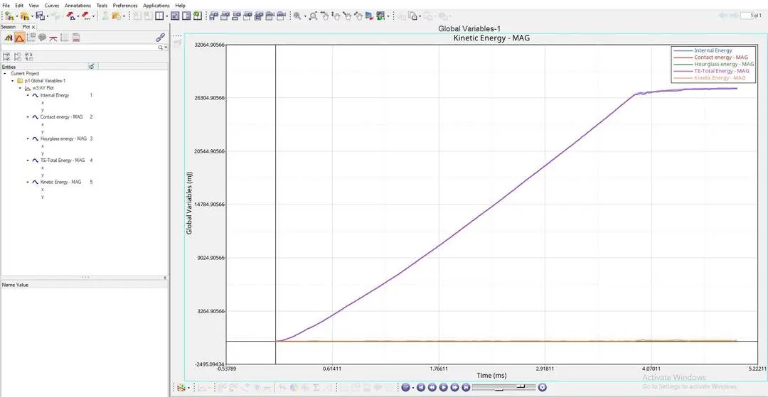
AS PER THE ABOVE GRAPH:
- "INTERNAL ENERGY PLOT" : This Internal Energy or Strain Energy keeps on increasing linearly due to the Increase in deformation of the plate untill it ruptures at a point, and after reaching this rupture point the Internal Energy is constant, this is because there will be a decrease in the Internal Energy, at this point some of the elements gets "Deleted or Detached" from the main shell component.
- "KINETIC ENERGY PLOT" : After the component reaching rupture point, we can see some distortion in the graph, which tells us that the elements which are getting "Detached", the "Detached" elements will be having some Kinetic energy in them.
- "HOURGLASS ENERGY PLOT" : Here we can see that this "Hourglass Energy" is "NILL" or "ZERO" through out the simulation and this is because we have used "QEPH ELEMENTS", which are Improved Integrated Elements.
CASE-2
RUNNING THE GIVEN MODEL BY IMPORTING "FAILURE_JOHNSON_0000.rad" TO SOLVER DECK:
IN THIS CASE WE HAVE TO CHANGE VALUES IN THE FAILURE CARD AS SHOWN BELOW IN THE FAILURE CARD:
Ifail_sh = 1
Dadv = 1
Ixfem = 1
CHANGED FAILURE CARD IMAGE:
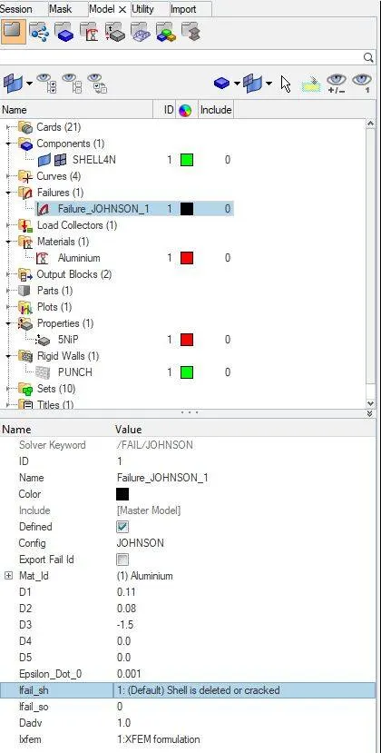
Here since we have changed "Ixfem" and "Dadv" as 1, Before the elements get deleted we can observe both "CRACK INITIATION" and "CRACK ADVANCEMENT".
DEFAULT MATERIAL CARD IMAGE:
DEFAULT PROPERTY CARD IMAGE:
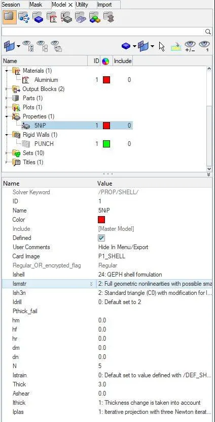
WE HAVE TO NOW START THE SIMULATION BY SAVING IT AS PER THE NAME SUGGESTED, "Law2_epsmax_crack".
RESULTS OF CASE-2 :
ERRORS ARE AS SHOWN BELOW:
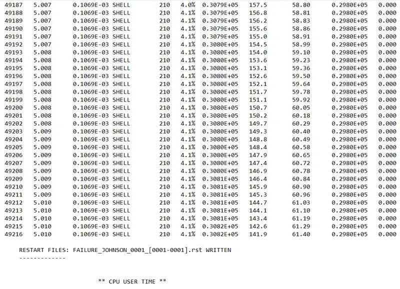
FROM THE ABOVE RESULT WE GET:
ENERGY ERROR = 4.1%
MASS ERROR = 0
NUMBER OF CYCLES = 49217
TOTAL ELAPSED TIME = 100.96 sec
WE HAVE TO OPEN "h3d" FILE IN HYPERVIEW TO SEE THE ANIMATION AS SHOWN BELOW:
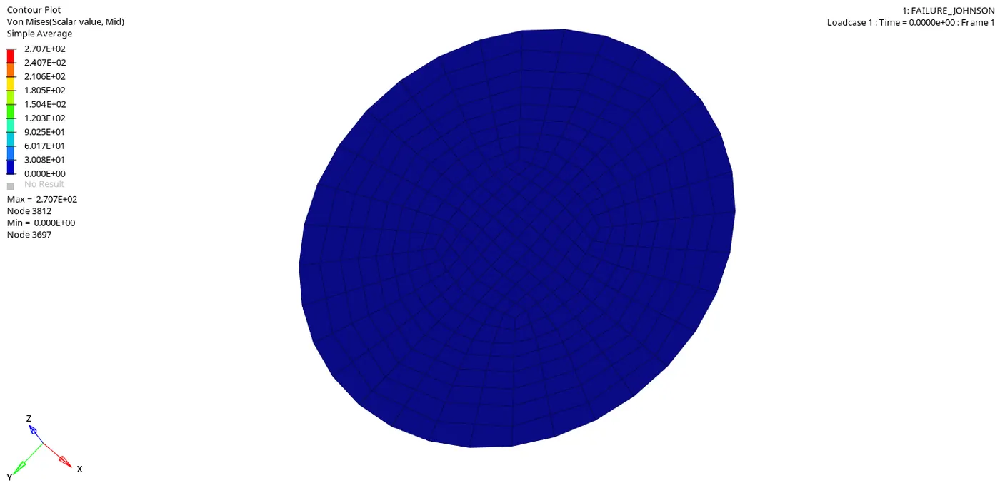
The "Maximum pressure" at which the "Rupture Plate" is getting failed is at 2.707E+02, here at this point the rupture plate experiences the "Maximum Plastic strain" and "Rupture Plate" will fail at this point.
Here we have changed "Ixfem" and "Dadv" as 1, so we can see "Crack Initiation" and "Crack Advancement" before the element gets detached.
Also the component will fail due to the pre defined values in the "MATERIAL CARD", such as "EPS_P_max" and "SIG_max0".
NOW WE HAVE TO OPEN A "TO1" FILE IN "HYPERGRAPH" TO PLOT ALL THE ENERGIES AS SHOWN BELOW:
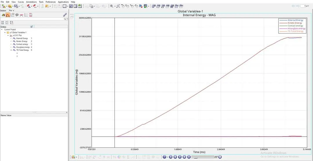
AS PER THE ABOVE GRAPH:
- "INTERNAL ENERGY PLOT" : This Internal Energy or Strain Energy keeps on increasing linearly due to the Increase in deformation of the plate untill it ruptures at a point, and after reaching this rupture point the Internal Energy is constant, this is because there will be a decrease in the Internal Energy, at this point some of the elements gets "Deleted or Detached" from the main shell component.
- Here "INTERNAL ENERGY" or "STRAIN ENERGY" is much higher than in the previous case, this is because Element will start getting deleted only after "Crack Advancement" and "Crack Initiation" starts happening.
- "KINETIC ENERGY PLOT" : After the component reaching rupture point, we can see some distortion in the graph, which tells us that the elements which are getting "Detached", the "Detached" elements will be having some Kinetic energy in them.
- "HOURGLASS ENERGY PLOT" : Here we can see that this "Hourglass Energy" is "NILL" or "ZERO" through out the simulation and this is because we have used "QEPH ELEMENTS", which are Improved Integrated Elements.
CASE-3
RUNNING THE GIVEN MODEL BY IMPORTING "FAILURE_JOHNSON_0000.rad" TO SOLVER DECK:
IN THIS CASE WE HAVE TO DELETE THE "FAILURE CARD" AS SHOWN IN THE BELOW BROWSER WINDOW IMAGE:
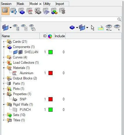
As we can see in the above image that we have deleted the whole "FAILURE CARD" image, and then the simulation is dine on this given model.
HERE WE FOLLOW THE DEFAULT MATERIAL CARDS AND PROPERTY CARDS.
WE HAVE TO NOW START THE SIMULATION BY SAVING IT AS PER THE NAME SUGGESTED, AS SHOWN BELOW:

RESULTS OF CASE-3 :
ERRORS ARE AS SHOWN BELOW:
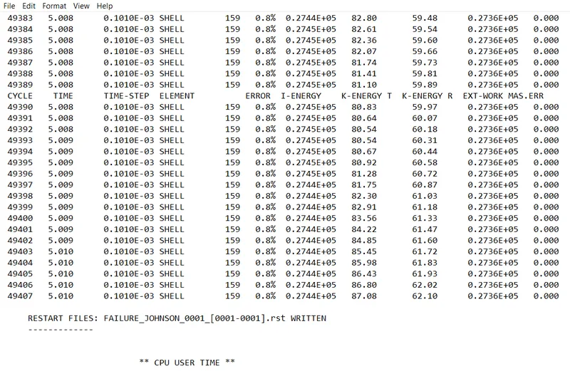
FROM THE ABOVE RESULT WE GET:
ENERGY ERROR = 0.8%
MASS ERROR = 0
NUMBER OF CYCLES = 49408
TOTAL ELAPSED TIME = 97.58 sec
WE HAVE TO OPEN "h3d" FILE IN HYPERVIEW TO SEE THE ANIMATION AS SHOWN BELOW:
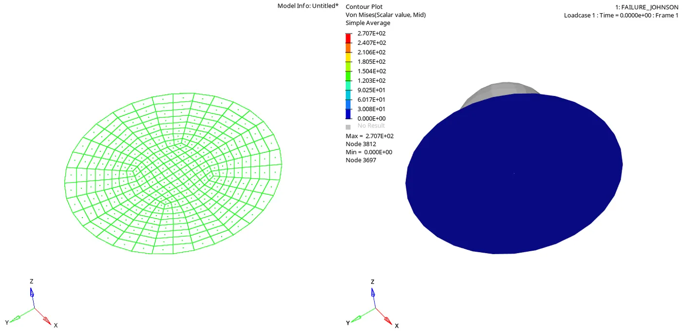
The "Maximum pressure" at which the "Rupture Plate" is getting failed is at 2.707E+02, here at this point the rupture plate experiences the "Maximum Plastic strain" and "Rupture Plate" will fail at this point.
In material card "SIG_max0" is defined as 425pa, so here as we can see in the above simulation, the "Rupture Plate" is failing at pressure 270.7pa, so this value is below the defined material card value, so we can conclude that the "RUPTURE PLATE" is failing because of the "PRE DEFINED" values of "EPS_P_max" and "SIG_max0".
NOW WE HAVE TO OPEN A "TO1" FILE IN "HYPERGRAPH" TO PLOT ALL THE ENERGIES AS SHOWN BELOW:
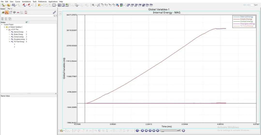
AS PER THE ABOVE GRAPH:
- "INTERNAL ENERGY PLOT" : This Internal Energy or Strain Energy keeps on increasing linearly due to the Increase in deformation of the plate untill it ruptures at a point, and after reaching this rupture point the Internal Energy is constant, this is because there will be a decrease in the Internal Energy, at this point some of the elements gets "Deleted or Detached" from the main shell component.
- Here we can see Internal energy is slightly fluctuated due to raise in Kinetic energy after element deletion.
- "KINETIC ENERGY PLOT" : After the component reaching rupture point, we can see some distortion in the graph, which tells us that the elements which are getting "Detached", the "Detached" elements will be having some Kinetic energy in them.
- "HOURGLASS ENERGY PLOT" : Here we can see that this "Hourglass Energy" is "NILL" or "ZERO" through out the simulation and this is because we have used "QEPH ELEMENTS", which are Improved Integrated Elements.
CASE-4
RUNNING THE GIVEN MODEL BY IMPORTING "FAILURE_JOHNSON_0000.rad" TO SOLVER DECK:
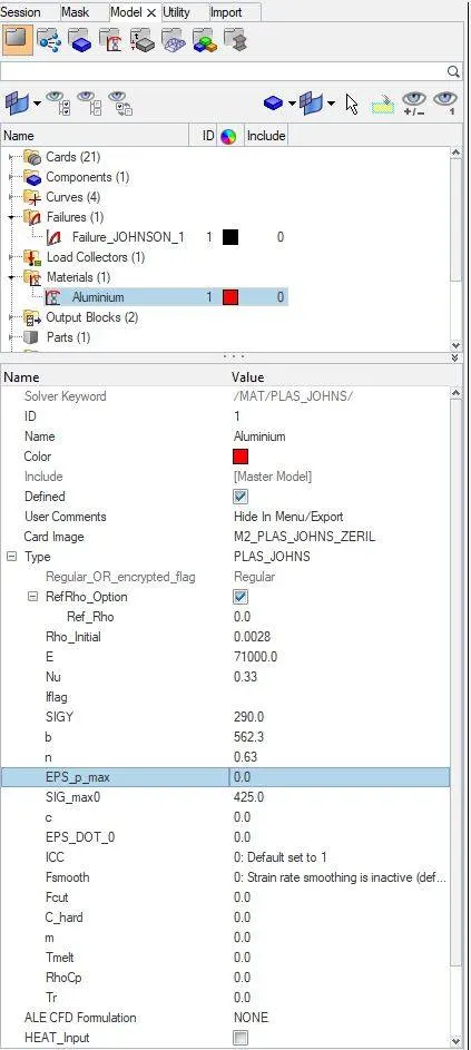
HERE WE DELETE THE VALUES OF "EPS_p_max" AND SET TO "0" AS SHOWN BELOW:
CHANGED MATERIAL CARD:
WE HAVE TO NOW START THE SIMULATION BY SAVING IT AS PER THE NAME SUGGESTED, AS SHOWN BELOW:

RESULTS OF CASE-4 :
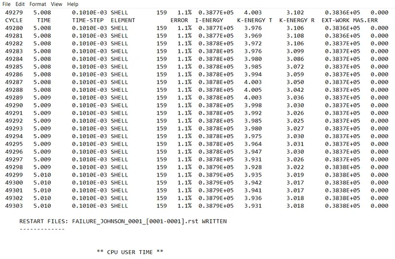
ERRORS ARE AS SHOWN BELOW:
FROM THE ABOVE RESULT WE GET:
ENERGY ERROR = 1.1%
MASS ERROR = 0
NUMBER OF CYCLES = 49304
TOTAL ELAPSED TIME = 97.74 sec
WE HAVE TO OPEN "h3d" FILE IN HYPERVIEW TO SEE THE ANIMATION AS SHOWN BELOW:
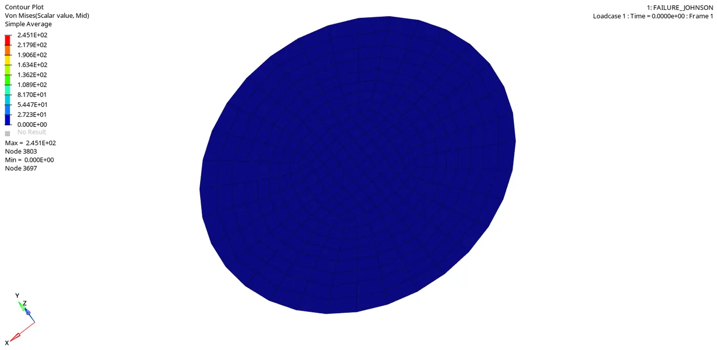
The "Maximum pressure" at which the "Rupture Plate" is getting failed is at 2.451E+02, here at this point the rupture plate experiences the "Maximum Plastic strain" and "Rupture Plate" will fail at this point.
Since material card is not defined "EPS_p_max", The component is failing due to the Default values of "Failure card criteria", And all those elements which are crossing this failure card criteria gets "DELETED" or gets "DETACHED" without getting "CRACKED", because "Ixfem" and "Dadv" are not defined for "CRACK INITIATION".
NOW WE HAVE TO OPEN A "TO1" FILE IN "HYPERGRAPH" TO PLOT ALL THE ENERGIES AS SHOWN BELOW:
AS PER THE ABOVE GRAPH:
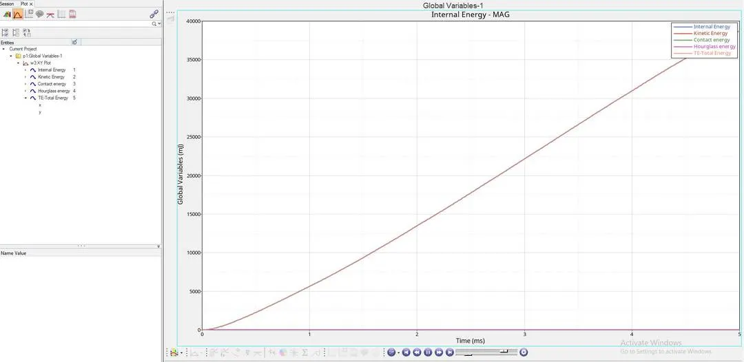
- "INTERNAL ENERGY PLOT" : This Internal Energy or Strain Energy keeps on increasing linearly due to the Increase in deformation of the plate untill it ruptures at a point, and after reaching this rupture point the Internal Energy is constant for "Very Short", this is because at this point some of the elements gets "Deleted or Detached" from the main shell component very quickly since we have not defined "EPS_p_max","Ixfem" and "Dadv".
- "KINETIC ENERGY PLOT" : After the component reaching rupture point, we can see some distortion in the graph, which tells us that the elements which are getting "Detached", the "Detached" elements will be having some Kinetic energy in them.
- "HOURGLASS ENERGY PLOT" : Here we can see that this "Hourglass Energy" is "NILL" or "ZERO" through out the simulation and this is because we have used "QEPH ELEMENTS", which are Improved Integrated Elements.
CASE-5
RUNNING THE GIVEN MODEL BY IMPORTING "FAILURE_JOHNSON_0000.rad" TO SOLVER DECK:
HERE WE CHANGE THE MATERIAL MODEL TO "LAW-1 ELASTIC" WITH SAME DENSITY, YOUNGS MODULUS AND POISSON'S RATIO AS SHOWN BELOW:
CHANGED MATERIAL CARD IMAGE: HERE NEW MATERIAL CARD IS CREATED AS SHOWN BELOW:
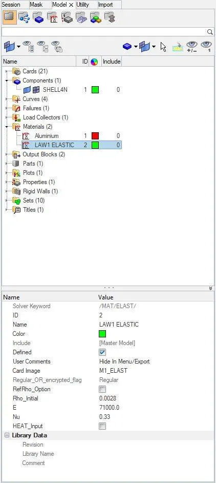
APPLYING MATERIAL CARD TO THE COMPONENT IS AS SHOWN BELOW:
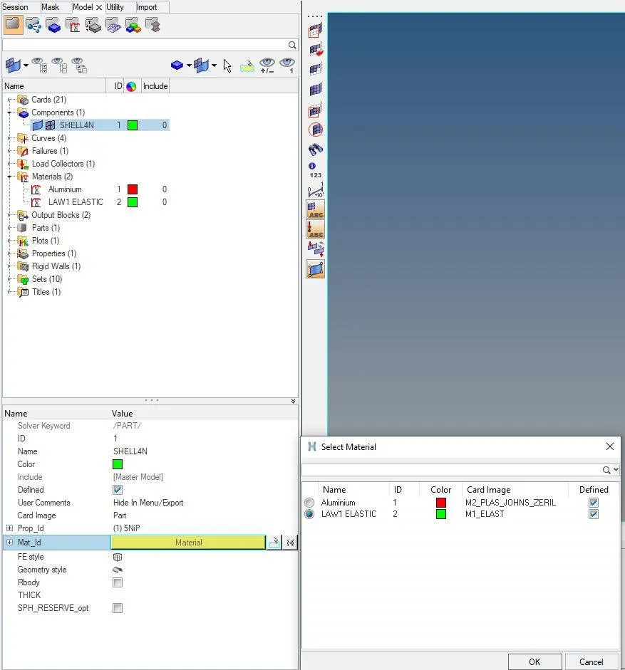
WE HAVE TO NOW START THE SIMULATION BY SAVING IT AS PER THE NAME SUGGESTED, AS SHOWN BELOW:

RESULTS OF CASE-5 :
ERRORS ARE AS SHOWN BELOW:
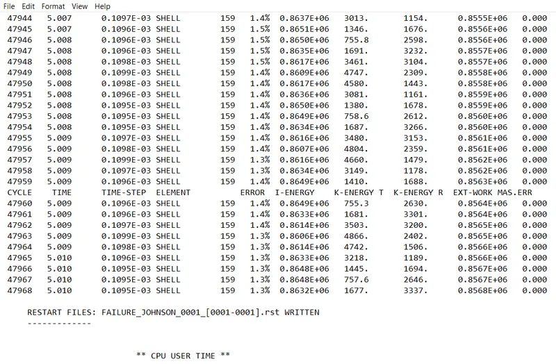
FROM THE ABOVE RESULT WE GET:
ENERGY ERROR = 1.3%
MASS ERROR = 0
NUMBER OF CYCLES = 47969
TOTAL ELAPSED TIME = 94.69 sec
WE HAVE TO OPEN "h3d" FILE IN HYPERVIEW TO SEE THE ANIMATION AS SHOWN BELOW:
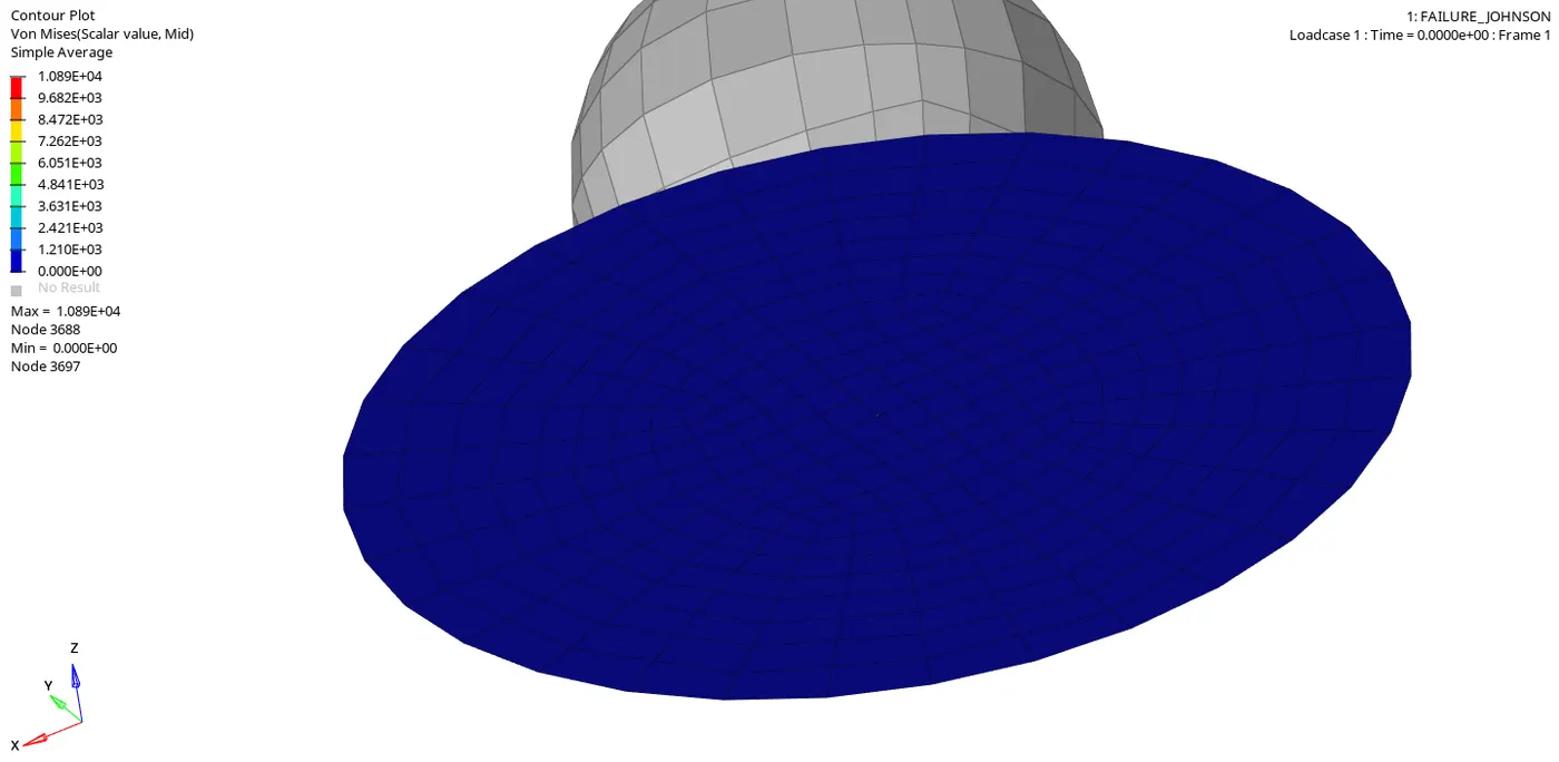
The "Maximum pressure" at which the "Rupture Plate" Reaches its maximum deformation is at 1.089E+04, Since the rupture plate is an "ELASTIC MATERIAL" , this material would not fail or break after the impact, but the material "PLATE" would come back to its "Original shape".
- Here we can see that there is no "PLastic Strain" experienced by this plate, Because we have modeled this plate material as pure "Elastic Material".
- Here Elements will not fail because there is no plastic strain happening in this case, but elastic strain is happening here.
NOW WE HAVE TO OPEN A "TO1" FILE IN "HYPERGRAPH" TO PLOT ALL THE ENERGIES AS SHOWN BELOW:
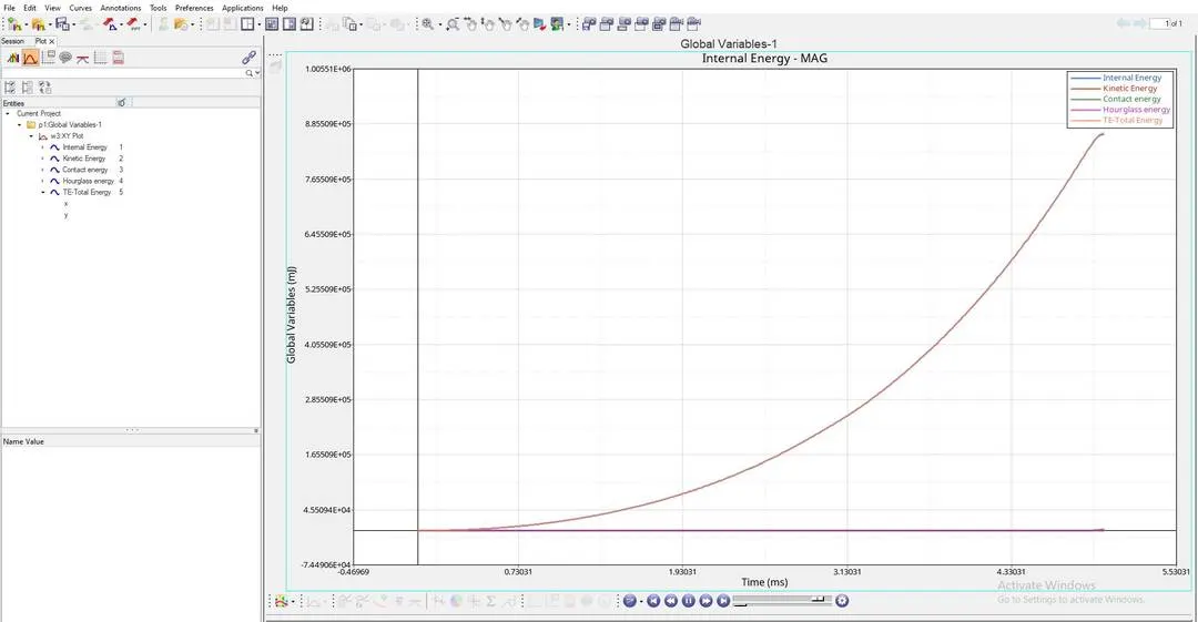
AS PER THE ABOVE GRAPH:
- "INTERNAL ENERGY PLOT" : This Internal Energy or Strain Energy keeps on increasing linearly due to the Increase in deformation of the plate, here we can see that internal energy will not become constant as we see in all previous cases, this is because of the "ELASTIC STRAIN" which is happening in the provided material.
- Since this is undegoing an elastic deformation the curve is "QUADRATIC" in nature.
- "HOURGLASS ENERGY PLOT" : Here we can see that this "Hourglass Energy" is "NILL" or "ZERO" through out the simulation and this is because we have used "QEPH ELEMENTS", which are Improved Integrated Elements, these elements nullifies if there are any "Hourglass Energy" is being created on the material.
CASE-6
RUNNING THE GIVEN MODEL BY IMPORTING "FAILURE_JOHNSON_0000.rad" TO SOLVER DECK:
PROPERTY CARD AND FAILURE CARD WILL BE IN DEFAULT AS WE KEPT IN FIRST CASE:
PLASTAB_CARD FOR THE CASE 6 IS PROVIDED IN THE VIDEO "MATERIAL-7" AND VALUES ARE DENOTED AS SHOWN BELOW:
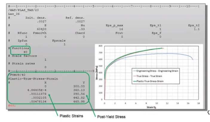
HERE WE CHANGE THE MATERIAL MODEL TO "LAW-36 ELASTO-PLASTIC" BASED ON THE DETAILS PROVIDED:
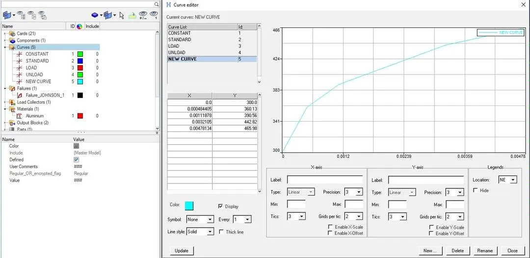
In this case we have a material base on "LAW-36" which is an "Elasto-plastic material" with some userdefined "Stress-Strain" curve functions which is obtained by "Lab Experiments".
FIRST WE HAVE TO DEFINE A "NEW CURVE" AND THE VALUES ARE FROM THE LAB EXPERIMENTS AS SHOWN BELOW:
IN THIS CASE WE HAVE TO DEFINE THE CURVE IN "N_func" AS SHOWN BELOW:
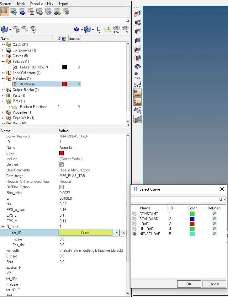
CHANGED MATERIAL CARD IMAGE: HERE NEW MATERIAL CARD IS CREATED AS SHOWN BELOW:
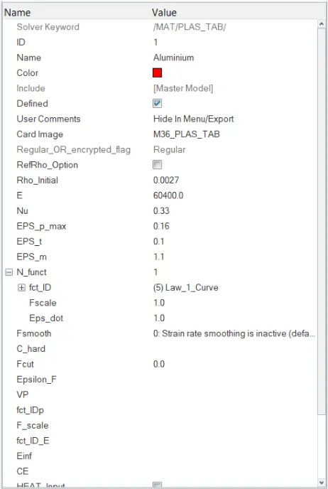
WE HAVE TO NOW START THE SIMULATION BY CLICKING ON TO "ANALYSIS":
RESULTS OF CASE-6 :
ERRORS ARE AS SHOWN BELOW:
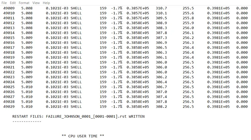
FROM THE ABOVE RESULT WE GET:
ENERGY ERROR = -1.7%
MASS ERROR = 0
NUMBER OF CYCLES = 49030
TOTAL ELAPSED TIME = 97.33 sec
WE HAVE TO OPEN "h3d" FILE IN HYPERVIEW TO SEE THE ANIMATION AS SHOWN BELOW:
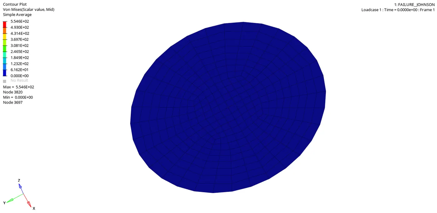
The "Maximum pressure" at which the "Rupture Plate" is getting failed is at 5.546+02, here at this point the rupture plate experiences the "Maximum Plastic strain" and "Rupture Plate" will fail at this point.
In material card "EPS_P_max" is defined as 0.16, so here as we can see in the above simulation, the "Rupture Plate" is failing at pressure 554.6pa, so this value is below the defined material card value, so we can conclude that the "RUPTURE PLATE" is failing because of the "PRE DEFINED" values of "EPS_P_max" , Default values of "FAILURE CARD" criteria and also due to "PREDEFINED STRESS STRAIN CURVE".
As we can see in the above simulation the material defined is from "LAW-36" with User defined stress strain curve, this kind of material is slightly behaving like a "BRITTLE" material.
NOW WE HAVE TO OPEN A "TO1" FILE IN "HYPERGRAPH" TO PLOT ALL THE ENERGIES AS SHOWN BELOW:
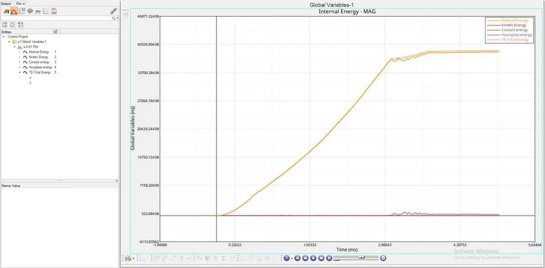
AS PER THE ABOVE GRAPH:
- "INTERNAL ENERGY PLOT" : This Internal Energy or Strain Energy keeps on increasing linearly due to the Increase in deformation of the plate untill it ruptures at a point, and after reaching this rupture point the Internal Energy is constant, this is because there will be a decrease in the Internal Energy, at this point some of the elements gets "Deleted or Detached" from the main shell component.
- Here "INTERNAL ENERGY" dips suddenly as seen in the above graph, this is because of the "BRITTLE" failure taking place in this case, here the internal energy dips more quicker when compared the graph in "CASE-1".
- "KINETIC ENERGY PLOT" : After the component reaching rupture point, we can see some distortion in the graph, which tells us that the elements which are getting "Detached", the "Detached" elements will be having some Kinetic energy in them.
- "HOURGLASS ENERGY PLOT" : Here we can see that this "Hourglass Energy" is "NILL" or "ZERO" through out the simulation and this is because we have used "QEPH ELEMENTS", which are Improved Integrated Elements.
CASE-7
RUNNING THE GIVEN MODEL BY IMPORTING "FAILURE_JOHNSON_0000.rad" TO SOLVER DECK:
HERE PROPERTY CARD AND THE FAILURE CARD WILL BE KEPT AS DEFAULT AS SHOWN BELOW:
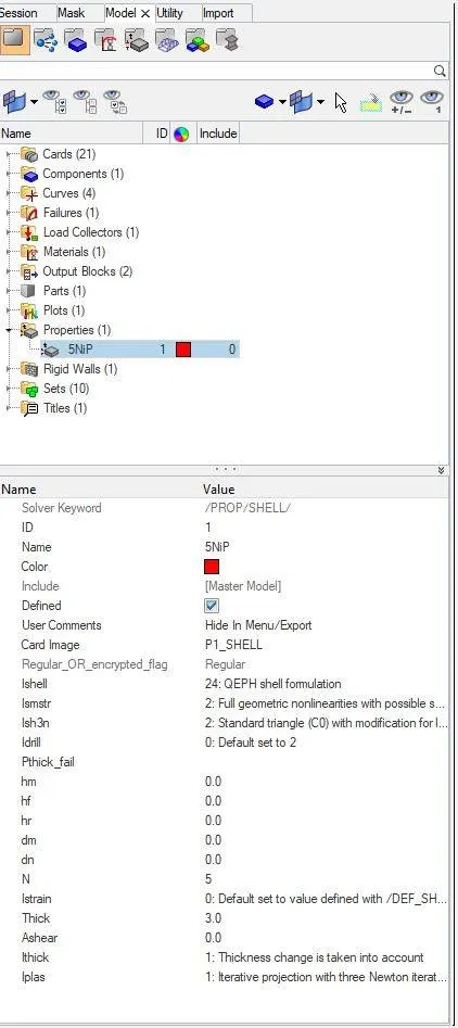
HERE WE CHANGE THE MATERIAL MODEL TO "LAW-27 ELASTIC PLASTIC BRITTLE" BASED ON THE DETAILS PROVIDED:
CHANGED MATERIAL CARD IS AS SHOWN BELOW:
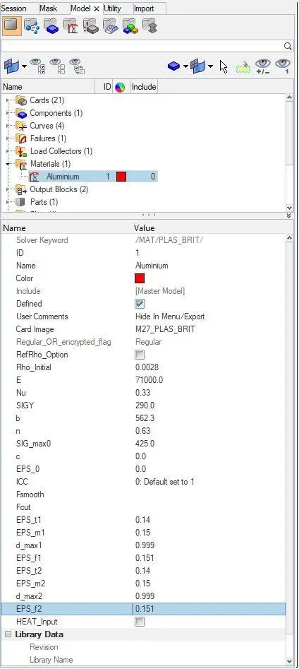
WE HAVE TO NOW START THE SIMULATION BY SAVING IT AS PER THE NAME SUGGESTED, AS SHOWN BELOW:

RESULTS OF CASE-4 :
ERRORS ARE AS SHOWN BELOW:
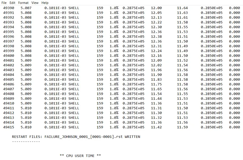
FROM THE ABOVE RESULT WE GET:
ENERGY ERROR = 1%
MASS ERROR = 0
NUMBER OF CYCLES = 49416
TOTAL ELAPSED TIME = 98.57 sec
WE HAVE TO OPEN "h3d" FILE IN HYPERVIEW TO SEE THE ANIMATION AS SHOWN BELOW:
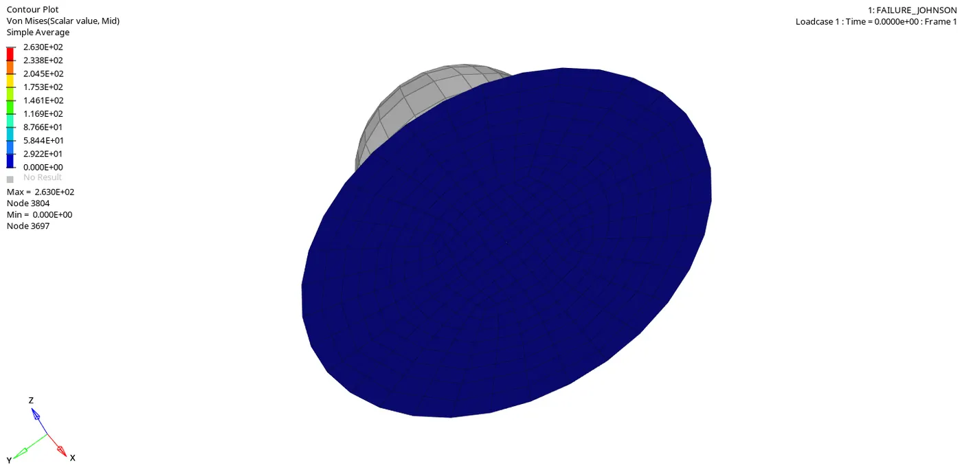
The "Maximum pressure" at which the "Rupture Plate" is getting failed is at 2.630+02, here at this point the rupture plate experiences the "Maximum Plastic strain" and "Rupture Plate" will fail at this point.
- Here as we can see from the above simulation the whole material is getting ruptured, the "Surrounding Elements" in the circumference of the component are getting deleted, this is due to the "BRITTLE" material which we have defined for this material in this case.
- In this material the elements are getting deleted not only where the impact is happening, but also the elements which are in the circumference of the component.
- This kind of element deletion can only happen when the material is "BRITTLE".
Here "Element Deletion" depends on the parameters which are defined in the "Material card", they are:
- SIG_max_0
- EPS_t1
- EPS_t2
- EPS_m1
- EPS_m2
- EPS_f1
- EPS_f2
- d_max1
- d_max2
NOW WE HAVE TO OPEN A "TO1" FILE IN "HYPERGRAPH" TO PLOT ALL THE ENERGIES AS SHOWN BELOW:
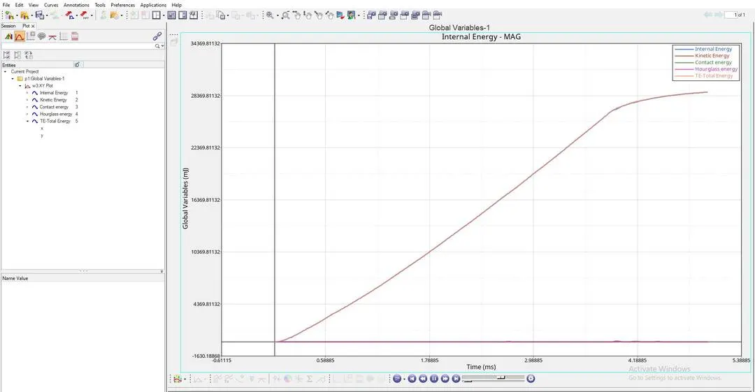
AS PER THE ABOVE GRAPH:
- "INTERNAL ENERGY PLOT" : This Internal Energy or Strain Energy keeps on increasing linearly due to the Increase in deformation of the plate untill it ruptures at a point, and after reaching this rupture point the increse in Internal Energy slows down ,at this point elements gets "Deleted or Detached" from the main shell component.
- Since the material used here is "BRITTLE" in nature we can no longer see "Internal energy" being constant as we see in the above cases.
- "KINETIC ENERGY PLOT" : After the component reaching rupture point, we can see some distortion in the graph, which tells us that the elements which are getting "Detached", the "Detached" elements will be having some Kinetic energy in them.
- "HOURGLASS ENERGY PLOT" : Here we can see that this "Hourglass Energy" is "NILL" or "ZERO" through out the simulation and this is because we have used "QEPH ELEMENTS", which are Improved Integrated Elements.
CONCLUSION:
CASE-1: We can see that some of the elements near impact region are getting "Deleted" due to both "EPS_p_max" and default "Failure card" criteria
CASE-2: We can see that some of the elements near the impact region are getting "Deleted" only after getting "Cracked".
CASE-3: We can see that some of the elements are getting "Deleted" near the impact region due to "EPS_p_max".
CASE-4: We can see that some of the elements are getting "Deleted" near the impact region due to default "Failure card" criteria.
CASE-5: Here not even one element is getting "Cracked" or "Deleted", because rupture plate is assigned with "Elastic material".
CASE-6: We can see that some of the elements near impact region are getting "Deleted" due to the pre-defined curve.
CASE-7: We can see that the elemants are getting deleted not only in the impact zone, but also in the peremeter or circumference of the material, because the material assigned is a "Brittle material".
So, we can conclude that "CASE-6" where we use "LAW-36", which is a "ELASTIC PLASTIC TABULATED" represents the on-field scenario.
.