Beam Crash Test
1.Using the crash beam file from the previous assignment, change the run time to 55 ms.
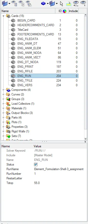
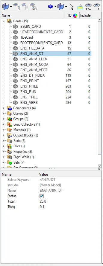
2. Change the number of animation steps during simulation to a minimum of 25 and maximum of 60.
AIM:
To run the base simulation with improved properties.
METHODOLOGY:
- Import the model.
- Run the simulation.
- Check the results and graphs.
PROCEDURE:
Simulation process:
Hypermesh :
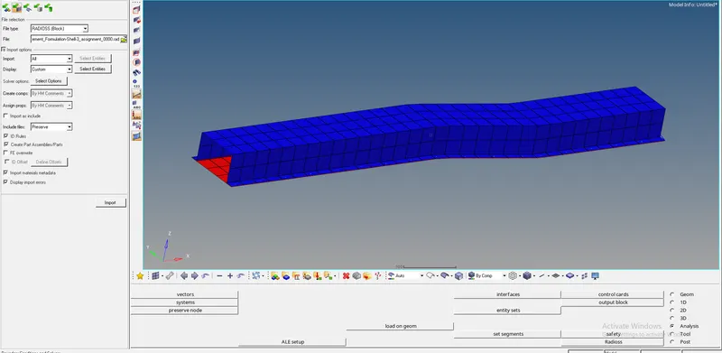
- Set the user file as ‘Radioss’.
- Click on “New” and select “Import as Solver deck”.
- Select the file and click on ‘apply’.
- Open the cards file and select the ‘Eng_Run’.
- Change the Tstop value.
- Select ‘Eng_Anim_DT’ and change the ‘Tfreq’ and ‘Tstart’ values.
- Go to Analysis panel and select Radioss option.
- Browse the input file which is 0000.rad file, tick on include connectors.
- In option box type “-nt 4” and click on Radioss.

Hyper View:
- Change ‘Hypermesh’ into ‘Hyperview’ from the toolbar.
- Tick the ‘load model’ and ‘load results’ options.
- Browse the .h3d file from the folder and click on ‘apply’.

HyperGraph 2D:
- Browse the T01 file in data file box and click on ‘Apply’.
- Select the properties like hourglass, contact energy, rigid wall forces and click on ‘apply’.
- Plot the properties in single window or separate windows.
Case 1:
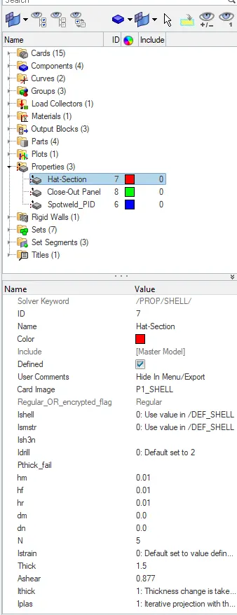
- Set the default properties as
- Ishell as zero
- Ismstr as ‘0’.
- Ish3n as ‘0’.
- N as ‘5’
- Ithick as ‘1’.
- Iplas as ‘1’.
Where Ishell selected element formulation for 4 nodes
Ismstr specifies small or large strain formation.
Ish3n selected element formulation for 3 nodes.
N represents as number of integration points.
Ithick determines the thickness under load.
Iplas chooses method for calculating post yield strains
- Set these values and run the simulation process.
- Plot all graphs and save it for further uses.
Case 2:
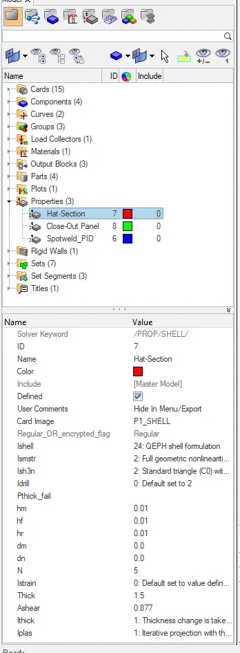
- Set the properties as
- Ishell as ‘24’
- Ismstr as ‘2’
- Ish3n as ‘2’
- N as ‘5’
- Ithick as ‘1’
- Iplas as ‘1’.
- Set these properties and run the simulation.
- Plot the graphs with various properties like
- Contact Energy
- Hourglass Energy
- Rigid wall forces.
- Resultant forces etc..
COMPARISION:
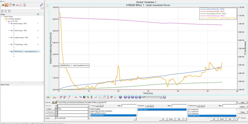
Case 1 report
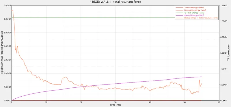
Case 2 report
- Hourglass energy and Contact energy are constant in case 2 compared to case 1 due to change in parameters of properties.
- Internal Energy is constant in case 2. In case 1 internal energy is decreasing gradually along the time.
- There is very slight difference in rigid wall force. Case 1 have slight higher value than case 2.
- Total enery is constant in case2, there is gradual decrease in internal energy in case 1.
Learning Outcome:
Definations like
HOURGLASS ENERGY:
Hourglass energy, which is work done by the forces calculated to resist hourglass modes, takes away from physical energy of the system. Severe hourglassing may be apparent without scaling displacements. Viscous forms generate hourglass forces proportional to components of nodal velocity contributing to hourglass modes.
CONCLUSION:
Cause of hourglass energy:
In hourglass, the node is not moved or transformed so there will be no stress recorded due to this no force is developed.
Steps to Avoid:
To avoid hourglass energy elements formulation for four nodes is to more accurate this happens only when Ishell is set as 24.