Assignment 3-2D Element Formulation Challenge
Aim
To run the simulation on crash beam model and comparision of results with base simulation and improved shell elements properties
Objective
- Using the crash beam file from the previous assignment, change the run time to 55 ms
- Change the number of animation steps during simulation to a minimum of 25 and maximum of 60
- Run the base simulation without any modification to elements properties
- At the end of the simulation, do the energy error and mass error checks and determine whether results would be accepted
- If acceptable, plot rigit wall forces, internal energy, hourglass energy, contact energy, total energy of the simulation
- Change all the shell elements properties to recommended properties, save this as separate, rad file and run the simulation
- Follow steps 5 and 6
- Create a brief report comparing all th results steps 5 and 6 for both simulations
- Comment whether there is any change in the results and why there is any change in the result.
Introduction
Element formulation:
Discretization is the process of dividing a model body into an equivalent system of many small bodies(Finite elements) interconnecting at nodes common to elements. There are many elements that we use in radioss to get the desired result. And these elements are categorized by the elments formulation techniques, which consists of the same elements but varies with respect to some parameters such as types of integration whichin the elements.
In general, there are three type of elements
- 1D elements(Line elements): This include Beam, trusses, spring.
- 2D elements(shell elements): This includes shell elements like quads(4-noded), tria(3-noded).
- 3Delements(Silid elements):This include solid elements like Tetra, Hexa elements
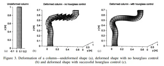
Hourglass
it is weired mode of deformation that occurs in under intergration shell elements where no stresses are produced. As stress are not produced it reduced the accuracy and true response of the analysis, this leads to inaccuracy result.
There are 2 method to control formation of hourglass
- Perturbation
- Physical stabilization
Procedure
Go to file -> import->solver deck.
This brings up the import menu.Here , we can select starter file to import, which is the ends with '0000.rad'.
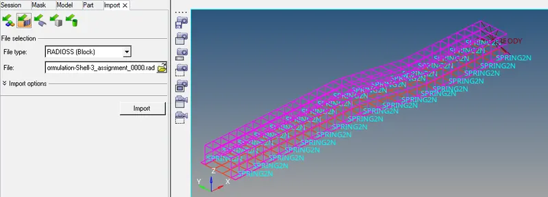
Using the crash beam file from the previous assignment, change the run time to 55 ms
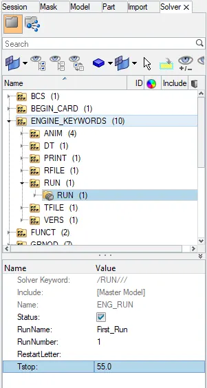
Now change the run time to 55 ms, go to solver tab->engine_keywords->run->eng_run
substitude the Tstop to 55 as shown below
Change the number of animation steps during simulation to a minimum of 25 and maximum of 60
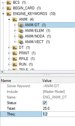
In the properties section, we can change the Tstartvalue to 25 and to calculate Tfrequency for a run time as 55ms with respect to the 45 animation steps.
Tfreq = Time step`divide` number of animation steps = 55/45 = 1.2
`therefore` The Tfreq is 1.2
This value is enter in the Tfreq in the card as shown below
Run the base simulation without any modification to elements properties
This simulation is performed with default property as shown below
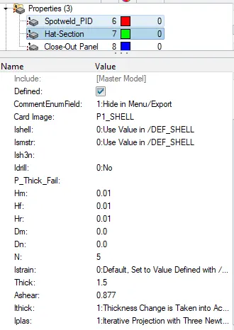
Next step is to run the simulation, Go to Analysis->Radioss-> enter the input file and option as - nt 4 as shown below, then click on Radioss
Here 'nt' means number of threads.

After clicking on Radioss, it will take some time to simulate then this page(shown below) will appear on the screen than click on results.
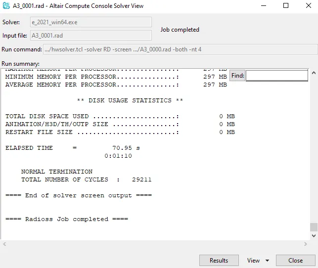
Than it will direct to Hyperview page and select the .h3d file which contain all the animation file.
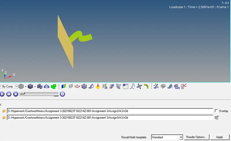
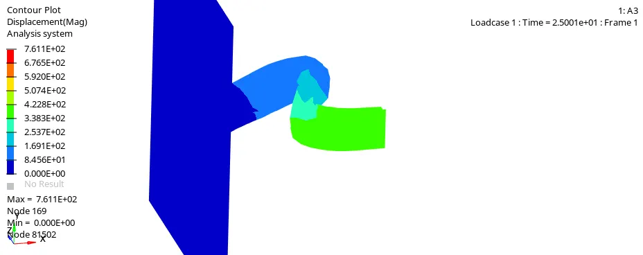
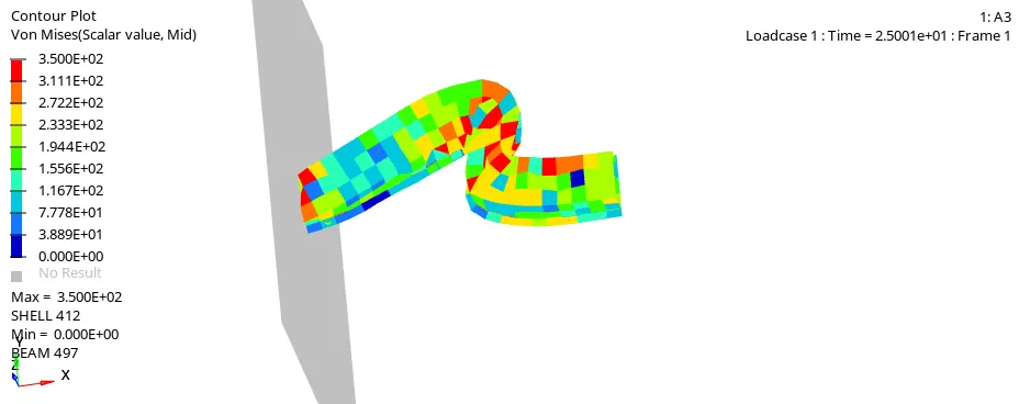
Go to contour command and simulate Displacement and Von-mises-stress.
At the end of the simulation, do the energy error and mass error checks and determine whether results would be accepted
To check on obtained value for energy error, internal energy, total energy, mass error from the output file (0001.out) in notepad
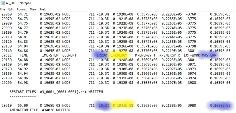
Fig:-Engine output file for default value
from above file,
Maximum energy error values: -10.3%
Internal energy: 0.933E+08 gm^2/s^2
Kinematic energy:0.3562E+08 gm^2/s^2
and Maximum mass error 0.1659E-03 kg
The acceptable tolerance for energy error is -15% to +5%. the obtain energy error are within tolerance value so accepted.
If acceptable, plot rigit wall forces, internal energy, hourglass energy, contact energy, total energy of the simulation
Since obtain energy and mass error are within tolerance value so accepted now we need to plot, to do so. Open Hypergraph 2D w can switch to it using same click selector option in the toolbar.
In the Hypergraph section we need to select .T01 file as shown below
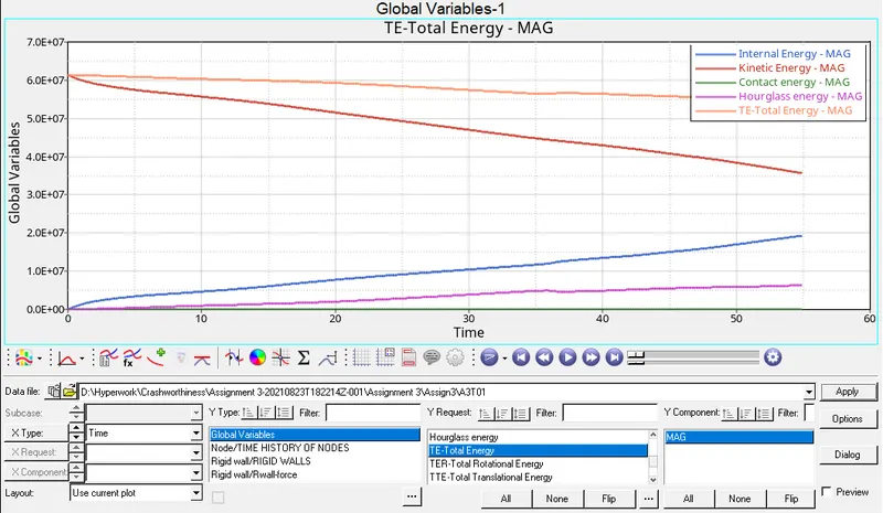
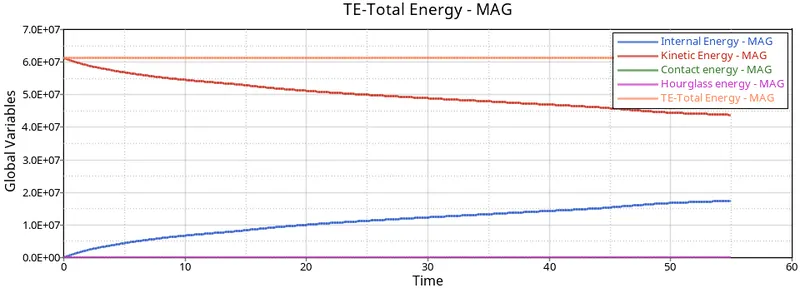
fig:- Different energy plot
- Internal energy
In beginning , there ia no displacement within the components, it start with zero when it is subjected to acceleration there will be a displacement.as the displacement increases internal energy increases
- Kinetic energy
We know that the formula of kinetic energy is 1/2mv^2 since the velocity is applied to the component, there will be a high velocity at the beginning. this velocity decreases with respect to the time due to deformation within the rail model
- Total energy
We kown that total energy is sum of kinetic and potential energy, as the hourglass energy increases , more amount of energy is not recorded. as the result total energy decreases.
- Hourglass energy
As the recommended properties are not specified in this case, there will be a deformation of elements with respect to the strain is not recorded. which depicts that the elements under goes an hourglass effect, and there will be no stability, so to balance the energy artificial energy is required that is called hourglass.
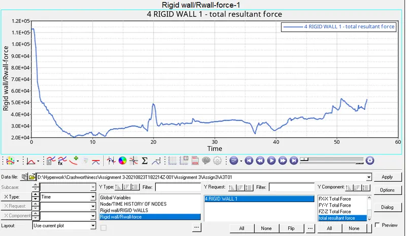
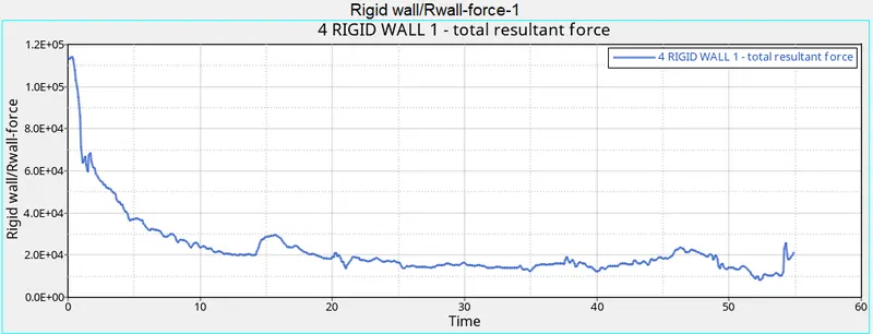
fig:-Rigid wall force
CASE 2
Change all the shell elements properties to recommended properties, save this as separate, rad file and run the simulation
We can repeat the process of importing the original slover deck and change the value of Tstop = 55 ms, Tfre = 1.2 and Tstart = 25.
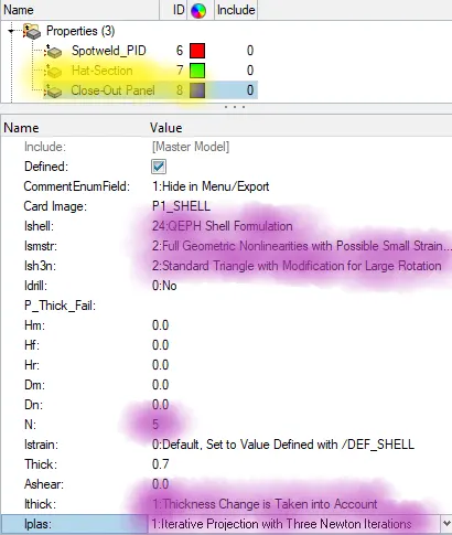
Change the Elements property as for given
| 2D elements properties | |
| Ishell = 24 | QEPH 4 noded shells are best combination of cost and accuracy |
| Ismstr= 2 | Fully geometric nonlinearties(default) with possible small strian formulation activation |
| Isk3N = 2 | standard 3- noded shell(Co) with modification for large rotation(default) |
| N = 5 | No. of integration point set to 5 for accuracy in bending |
| Ithick = 1 | thickness change is taken into account for accuracy |
| Iplas = 1 | iterative plasticity for good accuracy |
Follow steps 5 and 6
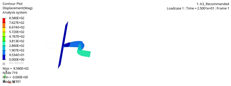
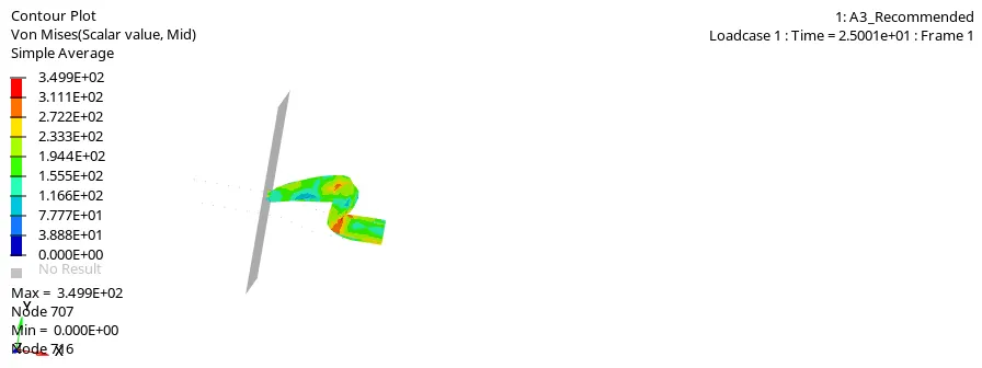
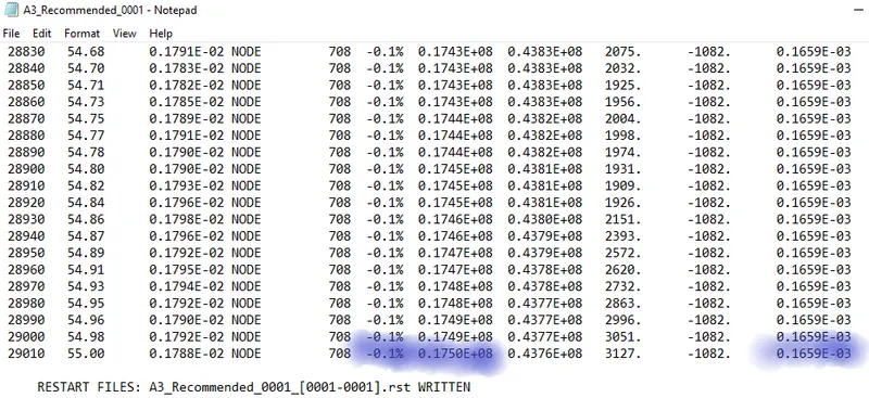
Fig:- Engine output file for recommended value
From above file,
Maximum energy error values: -0.1%
Internal energy: 0.1750E+08 gm^2/s^2
Kinematic energy: 0.4376E+08 gm^2/s^2
and Maximum mass error 0.1659E-03 kg
As we see, there is drastic reduction in hourglass energy error from -10.3% to -0.1%.
Create a brief report comparing all th results steps 5 and 6 for both simulations and comment on the result
To compare default and recommended elements properties, we need to import two .T01 file from two different cases.
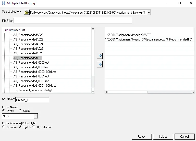
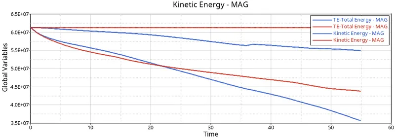
fig:- comparison on kinetic and total energy
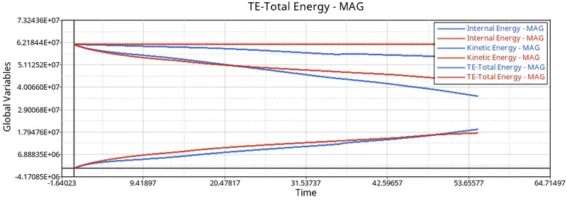
fig:- comparison on kinetic, internal and total energy
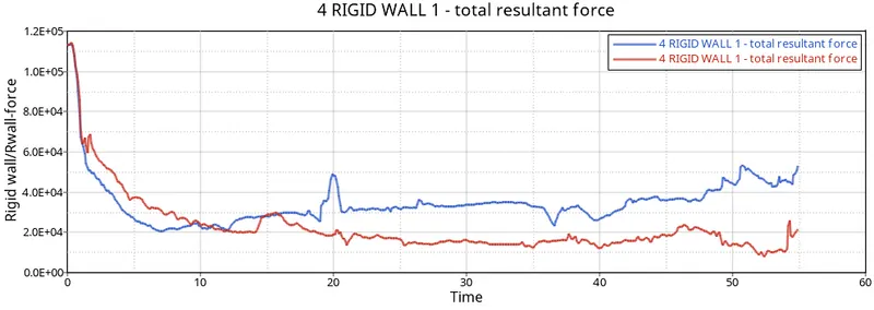
fig:- comparison on Rigid wall force
The obvoius different in the simulation is the reduction in the hourglass, the introduction of QEPH shell formulation in the second case, provide the artificial stiffness to the shell elements and reduce hourglass formation.
Hence Recommended properties is looking more natural and accuracy compare to default.
Th table below shows results comparison
| Comparision | Default case | Recommended case |
| Obtain maximum energy error | -10.3% | -0.1% |
| obtain maximum kinetic energy error | 0.3563E+0.8 | 0.4376E+0.8 |
| obtain maximum internal energy error | 0.1932E+08 | 0.1750E+08 |
| Reason for Hourglass energy | The element don't have physical stabilization | The element have physical stabilization because of assigning properties |
| Results | The result has less accuracy | The result are accuracy |
Learning outcomes
Able to understand
- About different property settings used for better simulation result in Hypermesh and Radioss
- Simulated the model
- Plots using Hypergraph 2D
Conclusion
All the reqired objective are obtained, simulation are carried out on both default and recommended elements property and compared both the cases.