Assignment 3-2D Element Formulation Challenge
OBJECTIVE
The main objective of this assignment is to compare two simulations with different shell element properties. The comparison would be between the one with default properties and one with the following properties:
| Parameters | Comment |
|
Ishell =24 |
QEPH 4 nodes shells are best combination of cost and accuracy. |
|
Ismstr=2 |
Full geometric nonlinearities (default)with possible small strain formulation activation in RADIOSS Engine. |
|
Ish3n=2 |
Standard 3 noded shell (C0)with modification for large rotation(default) |
| N=5 | Number of integration points set to 5 for accuracy bending. |
|
Ithick=1 |
Thickness change is taken into account for accuracy. |
|
Iplas=1 |
Iterative plasticity for good accuracy. The given questions will be answered throughout the process of comparison. |
QUESTIONS
1. Using the crash beam file from the previous assignment, change the run time to 55 ms.
2. Change the number of animation steps during simulation to a minimum of 25 and a maximum of 60.
3. Run the base simulation without any modification to element properties.
4. At the end of the simulation, do the energy error and mass error checks and determine whether the results would be acceptable.
5. If acceptable, Plot rigid wall forces, internal energy, hourglass energy, contact energy, the total energy of the simulations.
6. Change all the shell elements properties to recommended properties, save this as separate, rad files and run the simulation.
7. Follow steps 5 and 6.
8. Create a brief report comparing all the results from steps 5 and 6 for both simulations.
9. Comment whether there is any change in the results and why there is any change in the result.
THEORY
The following properties are changed for case 2.
Ishell">Ishell��ℎ���: This is the element formulation for 4-noded shells
Ismstr">Ismstr������: This property is to specify small or large strain formulation
Ish3n">Ish3n��ℎ3�: This is the element formulation for 3-noded shells
N: The number of integration points through the thickness
Iplas">Iplas�����: Method for calculating post-yield strains
Ithick">Ithick��ℎ���: Property that decides if the thickness is constant or to consider if element thins.
What is hourglass deformation and why it needs to be reduced?
Hourglass is basically a kind of deformation that is produced during the simulation in certain shell elements that have not been integrated appropriately. As a result, stress is not produced in these elements and this reduces the accuracy and true response of the structure during the simulation. This effectively results in incorrect displacement results with unrealistic representations of the simulated part.
How to reduce hourglass?
There are two ways to control hourglass formation. One is via Perturbation method and the other is through Physical Stabilization. It is important to deploy the right method based on the conditions of the simulation.
Perturbation is deployed by Q4 elements (Ishell">Ishell��ℎ���= 1, 2, 3, 4) and involves introducing an opposing force to stabilize whichever node it detects potential hourglass formations. This opposing force produces energy and that's known as 'hourglass energy'. As mentioned before, this method fails for large rotation and elastic loading-unloading cycles. In addition to that, it uses a simple under integrated method and this takes lesser time and computational power but that comes at the cost of accuracy.
This is why the Physical Stabilization method is the best method since it can be used in any case. This method is deployed by QEPH elements (Ishell">Ishell��ℎ��� = 24) and involves introducing an artificial stiffness. As a result, shell elements are controlled from a material level and in addition to that, they use an improved under-integrated method that provides the best compromise between computational cost and accuracy.
PROCEDURE:
Objective1: This first question requires us to change the run time to 55 ms. For that, we first need to import the solver deck file in question to RADIOSS
- Go to File >> Import >> Solver Deck. This brings up the import menu. Here, we can select the file we need to import. This file is called starter input deckfile, which is the file that ends with '0000.rad'.\
With the model imported, we can go ahead and change the run time to 55 ms (as required). To do that, we need to proceed to the solver tab in the sidebar. Proceeding to ENGINE_KEYWORDS > RUN > ENG_RUN, we can now edit properties of ENG_RUN in the small window below the tab.
Here, we can change the Tstop">Tstop����� value to 55.
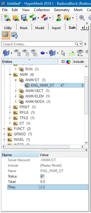
2. The next question requires us to change the number of simulation steps to a minimum of 25 and a maximum of 60. For this, we need to go to the same solver tab and proceed to ENGINE_KEYWORDS > RUN > ANIM > ANIM/DT. We shall be changing this particular attribute's properties.
-
To have 25 animation steps, the frequency should be Run time/Animation steps = 55/25 = 2.2
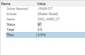
To have 60 animation steps, the frequency should be Run time/Animation steps = 55/60 = .916
-
In model tree, under CARDS collector, ENG_ANIM_DT card have a Tfreq of 1.0, which is changed to 2.2 and .916 for the simulation asked
3. Next requirement is to run the base simulation. For that, we need to save the current file with edited parameters. This can be carried out via the analysis process.
For this, we can go to the 'Analysis' section from the bottom panel.
There, we can select RADIOSS.
In the next section, we are given the option to save the file before running it in the solver. We can go ahead and give it a different name from the base file to avoid confusion. Clicking 'save as' lets us do that.
After saving, before running it into the solver, we can activate 'include connectors' and in the options bar, we need to enter "-nt 4" to increase the processing power of the solver (as in to use all 4 cores). After that, we can click 'Radioss' to activate the solver and it processes t the file. We get a solver window that tells us what's going on in the process. It runs for several seconds before finishing and letting us know about completion.
After analysis, the .out file is viewed to check whether the energy error and mass error fall within the acceptable range
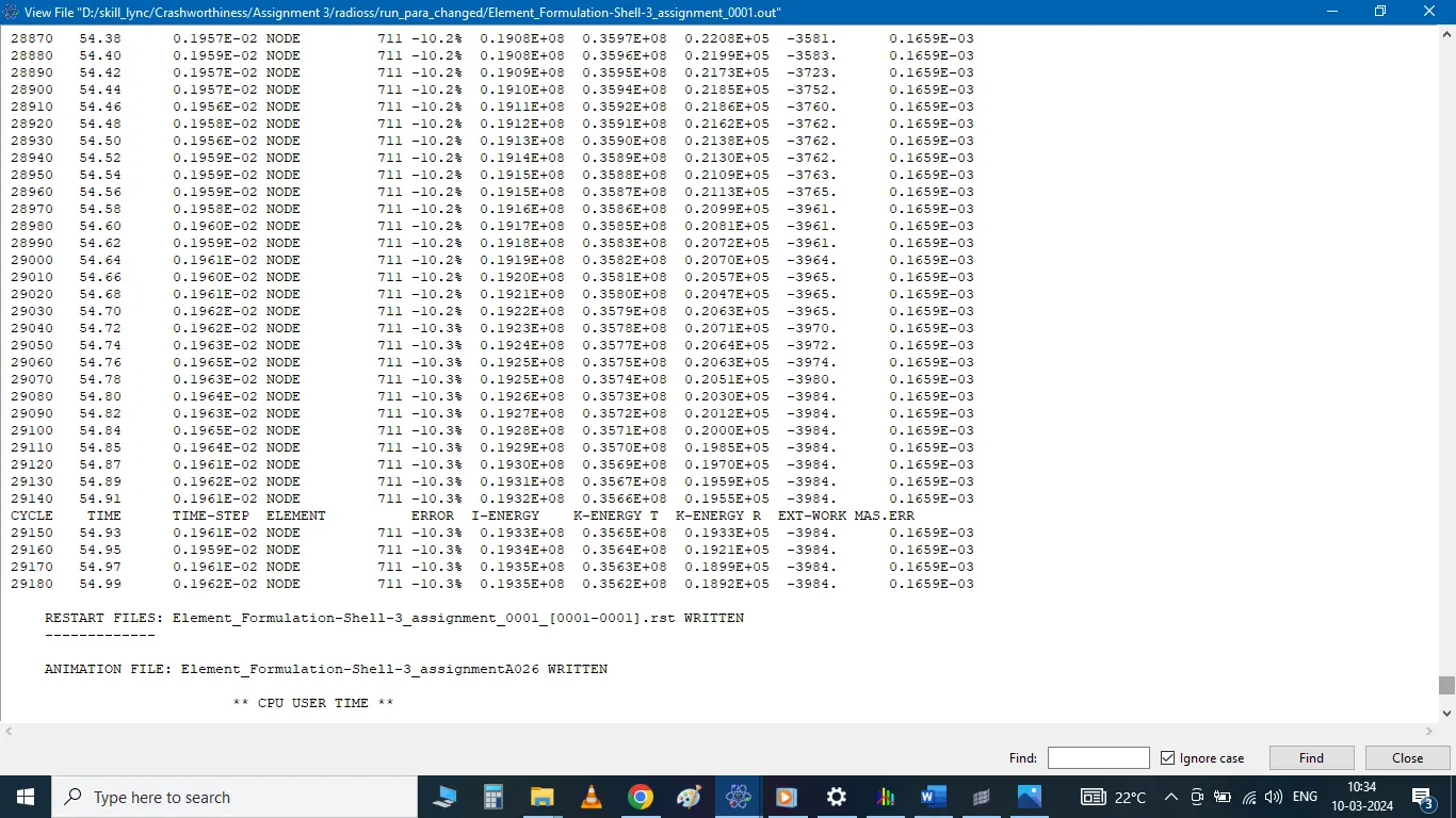
- The energy error starts from 0% to 10% which is within acceptable range.
- Mass error stays constant throughout the simulation at 0.1659e-03 which is also within the acceptable range.
- Since the error values are acceptable, rigid wall forces, internal energy, hourglass energy, contact energy, total energy of the simulation are plotted with the help of hypergraph 2-D
- hyperview is opened to view the simulation (deformation of the crush tube).
- model and results (h3d file) are loaded from the newly created folder
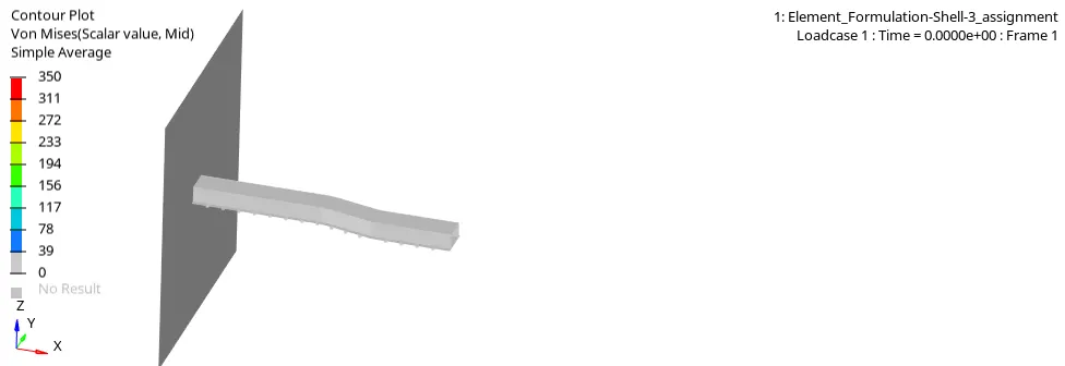
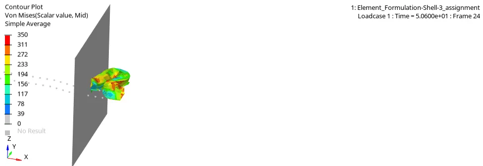
- animation shows how the crush tube deforms and stress values under the action of force.
- To plot the specific graphs, hyper graph 2-d is selected.
- File named Element_Formulation-Shell-3_assignmentT01 is opened.
- Specified energies are plotted against time on the same plot as shown below:
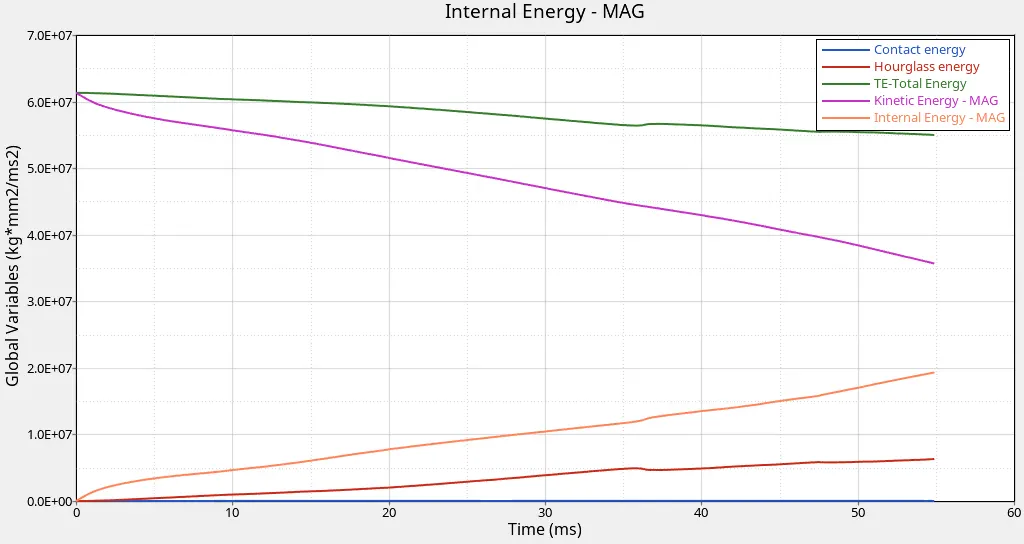
· Internal energy increases throughout the simulation which is due to the force developed on tube due to deformation.
· There is a slight increase in hourglass energy throughout the simulation.
· Contact energy remains zero throughout the simulation.
· Total energy of the system has a slight decrease from the start to end of the simulation.
· A new plot is created to plot the rigid wall forces. 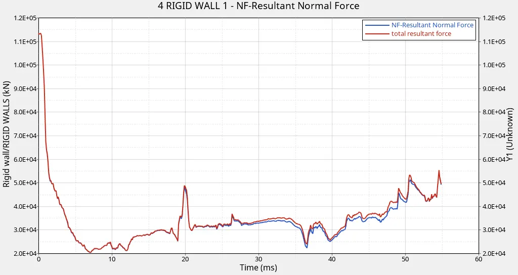
- Total resultant force and Resultant normal rigid wall forces are plotted against time as shown above.
- The rigid wall force curve is of a non-linear behaviour, which is due to the variation in the force exerted by the crush tube on the wall throughout the simulation.
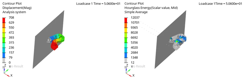
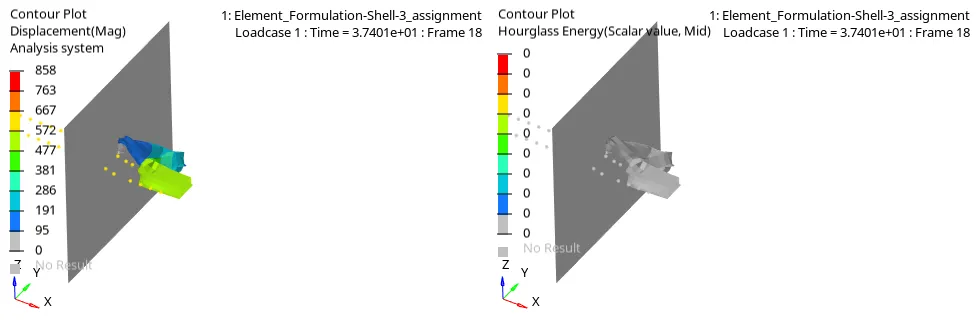
- Contour plot of Hourglass energy is obtained using contour option under hyperview.
 Changing the shell elements properties to recommended properties
Recommended properties:
| Parameters | Comment | |
|
Ishell =24 |
QEPH 4 nodes shells are best combination of cost and accuracy. | |
|
Ismstr=2 |
Full geometric nonlinearities (default)with possible small strain formulation activation in RADIOSS Engine. | |
|
Ish3n=2 |
Standard 3 noded shell (C0)with modification for large rotation(default) |
|
| N=5 | Number of integration points set to 5 for accuracy bending. | |
|
Ithick=1 |
Thickness change is taken into account for accuracy. |
|
|
Iplas=1 |
Iterative plasticity for good accuracy. |
The shell elements properties are modified to recommended property value
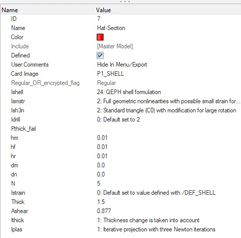
The file is run after making above changes and output file is opened:-
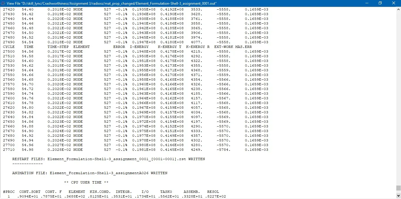
The energy error starts from 0% to -0.10% which is within acceptable range.
Mass error stays constant throughout the simulation at 0.1659e-03 which is also within the acceptable range.
Since the error values are acceptable, rigid wall forces, internal energy, hourglass energy, contact energy, total energy of the simulation are plotted with the help of hypergraph 2-D
File named Element_Formulation-Shell-3_assignmentT01 is opened.
Specified energies are plotted against time on the same plot as shown below:
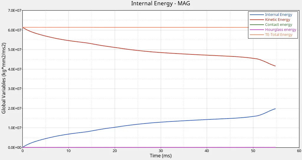
· From the plot obtained for simulation after modification to element properties, following observations are made:
· Internal energy increases throughout the simulation which is due to the force developed on tube due to deformation.
· Total energy remains same throughout the simulation.
· Hourglass energy and contact energy remains zero and follows the origin throughout the simulation.
· A new plot is created to plot the rigid wall forces.
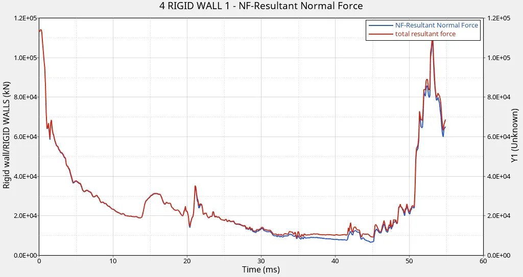
Total resultant force and Resultant normal rigid wall forces are plotted against time as shown above.
The rigid wall force curve is of a non-linear behaviour, which is due to the variation in the force exerted by the crush tube on the wall throughout the simulation.
COMPARISON :-
When recommended properties are changed from the base values, simulation results shows that
- Total Energy remains constant rather than decreasing which is clear from the energy error which went till-10% now changed to -0.1%.
- Hourglass energy which was increasing changed to zero throughout the simulation.
- Contact energy characteristics are same in both cases.
- Internal energy is having a gradual increasing characteristics in both the cases.
- Rigid wall forces also decreased to a lower value than that of default value rigid wall force value.
- Contour plots shows that there is a slight increase in maximum displacement of element with recommended property values.
Hourglass energy:
- In FEA, the hourglass mode is also known as the "zero energy mode" because deformation energy of elements under hourglassing mode is zero. But the hourglass energy is not equal to zero.
- In a shell element which have several integration points, for reduced computation effort, a reduced integration which uses a single integration point is used. In such cases, the deformation mode from the analysis results will be false. This is called hourglass phenomenon.
- This is just a nonphysical zero energy mode which leads to excessive element distortions. The more structured and less distorted your elements are, the better the results.
To solve this problem,
- Mesh Refining is a solution. Hourglassing is more prone in coarse mesh.
- Fully Integrated elements are better though computational time increases vastly and fully integrated elements are prone to shear locking.
- Providing a small arbitrary stiffness in the mode in which hourglass deforms. This is only a FEA point of view and in actual physical system, there is no such stiffness. This is what is called as Built in hourglass controls.
- Viscous damping.