2D Element Formulation
AIM :-
The main aim of this challenge is to :
1.Change the run time to 55 ms.
2. Change the number of animation steps during simulation to a minimum of 25 and a maximum of 60.
3. Run the base simulation without any modification to element properties.
4. At the end of the simulation, do the energy error and mass error checks and determine whether the results would be acceptable.
5. If acceptable, Plot rigid wall forces, internal energy, hourglass energy, contact energy, the total energy of the simulations.
6. Change all the shell elements properties to recommended properties, save this as separate, rad files, and run the simulation.
7. Follow steps 5 and 6.
8. Create a brief report comparing all the results from steps 5 and 6 for both simulations.
9. Comment whether there is any change in the results and why there is any change in the result.
The recommended shell element properties are given below:
| Parameters | Comment | |
|
Ishell =24 |
QEPH 4 nodes shells are best combination of cost and accuracy. | |
|
Ismstr=2 |
Full geometric nonlinearities (default)with possible small strain formulation activation in RADIOSS Engine. | |
|
Ish3n=2 |
Standard 3 noded shell (C0)with modification for large rotation(default) |
|
| N=5 | The number of integration points set to 5 for accuracy bending. | |
|
Ithick=1 |
Thickness change is taken into account for accuracy. |
|
|
Iplas=1 |
Iterative plasticity for good accuracy. |
Solution 1 :-
Run Radioss model without modification in Property
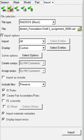
- We first import the radioss solver modelin our window, withimport solver option:
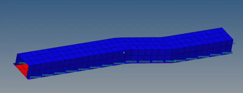
- Imported model is in wirefram , we will use the shaded element with mesh line visualization option to view the surface of model with mesh lines.
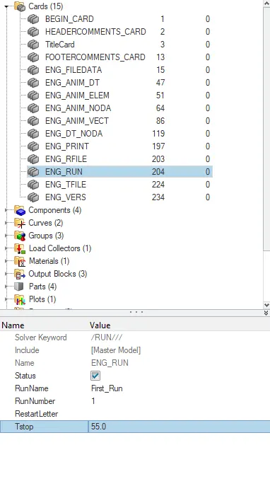
- As mentioned in the question, the run time or time step is 55 ms. We will modify the ENG_RUN card to stop simulation at 55 ms.
- The next step is to select the number of animation steps required. The number of animation steps can be between 25 to 60.
- In this challenge, the number of animation steps selected is 40.
- Now to calculate the frequency for a run time as 55 ms with respect to the 40 animation steps.
- The formula used :-
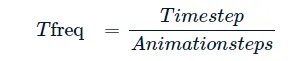
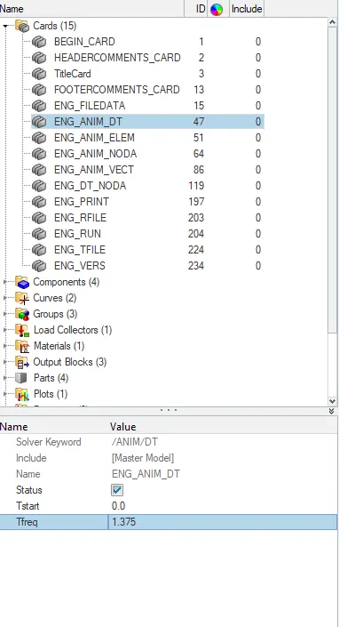
On calculation we get 1.375.
- Now we need to edit in the card named "ENG_ANIM_DT" as shown below:
CASE-1 :-
Simulation :-
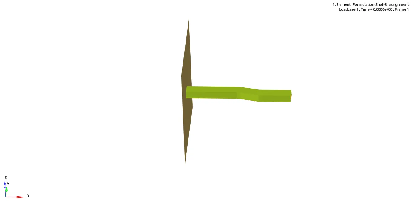
- The next step is to run the simulation. For doing that, select the "radioss" option in the "Analysis" panel.
- After entering into the radioss panel, Initially, the file should be saved in some folder using the "save as"option.
- Then in the options column type "-nt 4" to run the simulation faster.
- Then hit on the Radioss option to run the simulation.
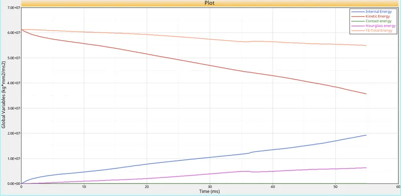
- Use the Hypergraph option and load the "T01" file and plot the different energy graphs include internal, Kinetic energy, Contact energy, Hourglass energy, and Total energy.
- Due to the velocity applied on all elements, the plate possesses kinetic energy and this kinetic energy is transferred into strain energy since energy can neither be created nor be destroyed according to the law of conservation of energy.
- Initially, the kinetic energy will be very high due to the force applied and after which this energy is transferred as internal energy(Strain energy).
- Due to this, the kinetic energy is decreasing, and simultaneously the internal energy is increasing.
- Since the energy is transferring from one form to another the total energy almost remains constant.
- Hourglass is a weird mode of deformation that occurs in under integrated shell elements where no stresses are produced.
- As stresses are not produced, it reduces the accuracy and true response of the structure.
- This leads to inaccurate strain and displacement results with unrealistic deformations.
- In total energy, the hourglass energy is not taken into account and it can be clearly seen as hourglass energy increases the total energy is decreases and an energy error will be created.
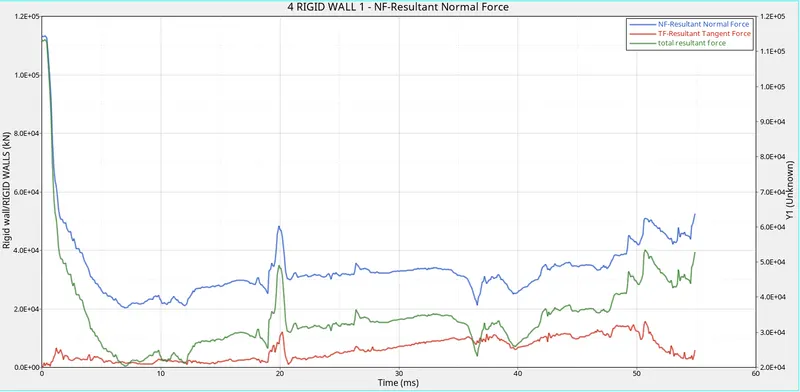
- Then using the rigid wall force option plot normal force, tangent force, and total resultant force.
- The rigid-wall normal force is initially high.
- At this point, the beam initially hits the wall.
- As time increases, the normal force starts decreasing due to the absorption of energy by the elements as strain energy.
- The frictional force(Tangent force) between beam and wall is initially zero and it starts increasing and fluctuates due to the contact of beam and wall.
- The frictional force increases around 20ms because at this time, the beam is tackling against the wall and so the contact area with the wall is increased and it increases the frictional force.
- The total resultant force is the summation of the normal force and tangent force.
Solution 2 :-
With Changing Element Properties
Hat Properties
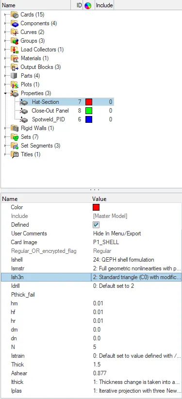
Close - Out Panel
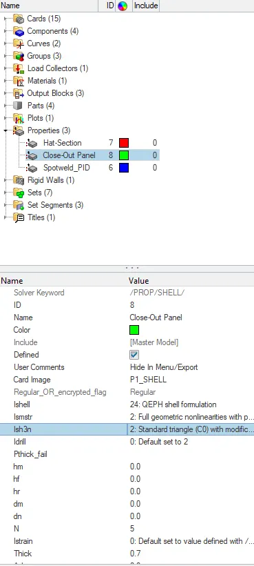
- After changing properties as per our requirement using the "radioss" option is used in the "Analysis" panel.
- After entering into the radioss panel, the file can be saved in a separate folder using the "save as"option.
- Then in the options column, type "-nt 4" to run the simulation faster.
- Then hit on the Radioss option to run the simulation.
RESULT :-
The "_001.0ut" file opened in order to check the energy error.
The maximum energy error and mass error at the end of the simulation are -0.1 % and 0.1659E-03. Basically energy error must be between -15% to 5% at the end of the computation, as per the condition.
As per the condition, the energy error is -0.1% which is acceptable and we can move for plotting the graphs.
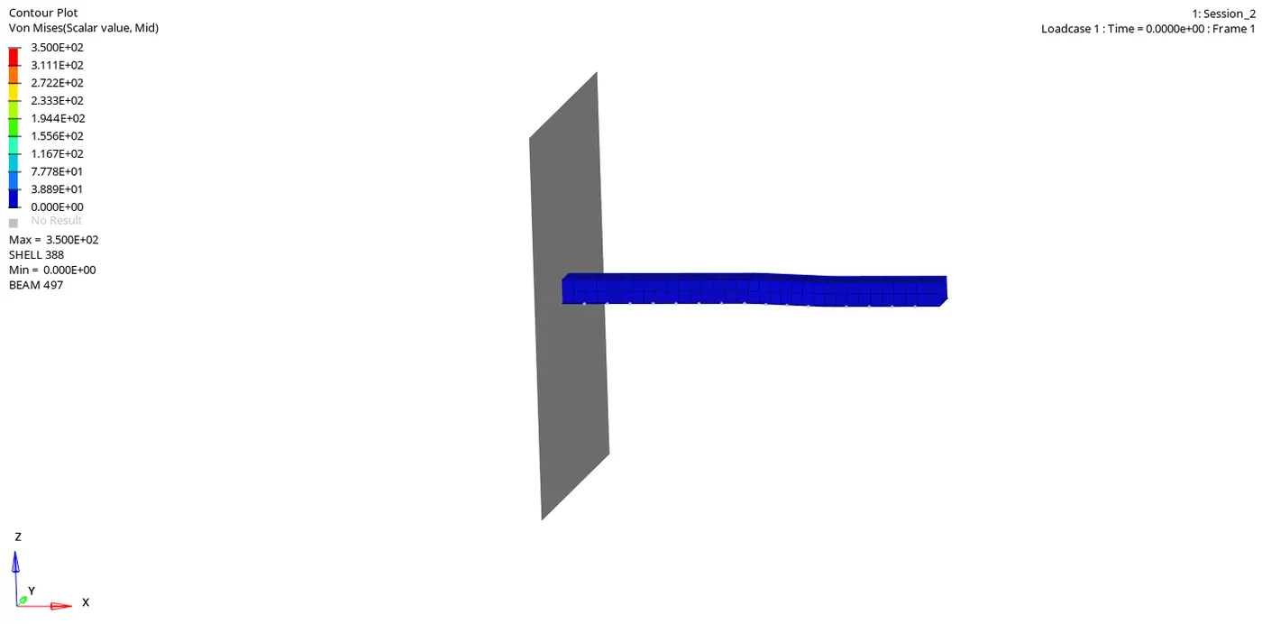
Animation
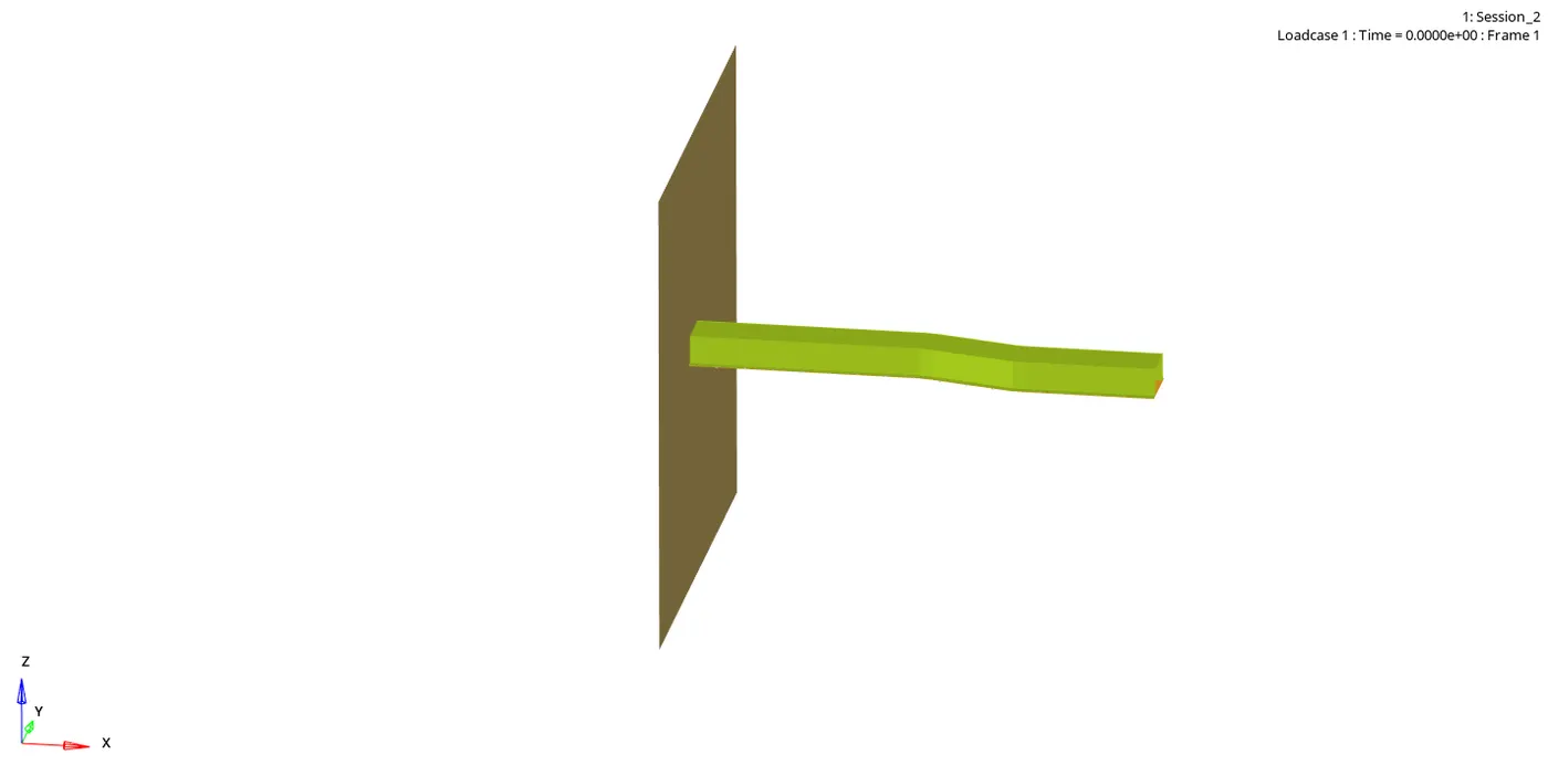
Von-Misses Stress Animation
Plot :-
- Use the Hypergraph option and load the "T01" file and plot the different energy graphs include internal, Kinetic energy, Contact energy, Hourglass energy, and Total energy.
- The internal, Kinetic energy is discussed in the above plot, and in this case also, it remains the same.
- Since the element type is changed into QEPH type, there is no formation of hourglass energy due to the improvement in the integration method.
- Due to the absence of hourglass energy, the total energy remains constant throughout the simulation and so the energy error is also greatly reduced.
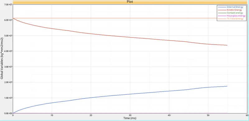
- Then using the rigid wall force option plot normal force, tangent force, and total resultant force.
- The basic idea of normal force, tangent force, and total resultant force as discussed in the case-1 will remains the same.
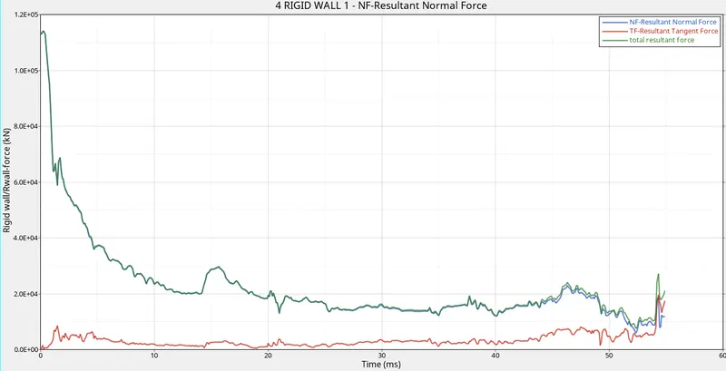
Comparison of Plots :-
The major difference observed include:
- In case 1, The hourglass energy occurs and in case 2 it is zero due to the improvement in the integration method.
- In case-1, Due to hourglass energy and reduced integration method, there will be around -10.3% of energy error occurs whereas in case 2 it is greatly reduced to about -0.1%.
- In case -1, The normal force against the rigid wall is higher at the end of simulation whereas in case-2 it is reduced.
- Incase-1, The Frictional force is increased around 20ms due to the tackling of beam against the wall and this situation is not occurring in case-2, the frictional force is not fluctuating to a greater extent as observed in case-1.
Conclusion :-
- Understands how to run the simulation in Radioss.
- Understands how to change elemental properties in the cards.
- Understands how the changes in the elemental properties alter the results.