Assignment 3-2D Element Formulation Challenge
Assignment 3-2D Element Formulation Challenge
Objective: Simulating and comapring the crash beam with given two different parameters.
Case 1 Setup and Execution:
The files given are radioss files, the run time and the animation steps can be edited from either opening the Elemental_Formulation_Shell-3_Assignment_0000.rad file in text format or importing it to Hypermesh.
After opening the rad file in hypermesh,
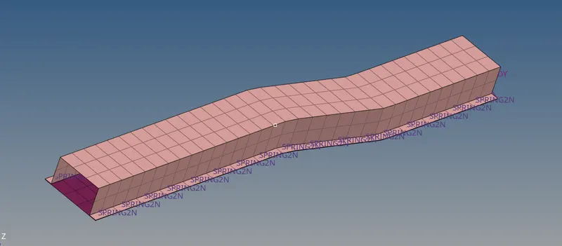
The run time and animation save steps are edited from solver browser -> Engine Keywords
For Run time -> Run and changing Tstop to 55 ms
For Animation save interval ANIM -> ANIM/DT and changing Tfreq to 2.2 ms
This 2.2 ms is for getting minimum 25 animation steps
After making these changes, other elemental properties are kept the same
and simulation is started by
Analysis panel -> Radioss
Here export options -> all
run option -> analysis
run number -> 1 and option space -> -nt 4 and starting Radioss
By doing this new window opens showing the simulation steps and it continues.

Here energy error is 10.3% which is less than 15 % but greater than 5% and so results not good but are acceptable.
Case 2 Setup and Execution:
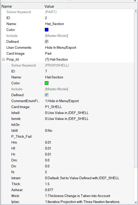
After case 1 simulation is done, the shell elemental properties are changed to recommended properties as shown.
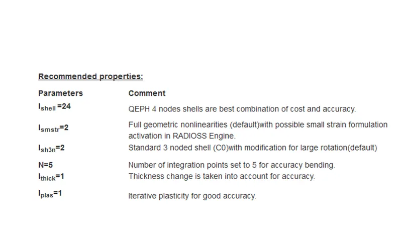 These can be edited by opening shell properties of Hat_section and close-out_panel from model browser.
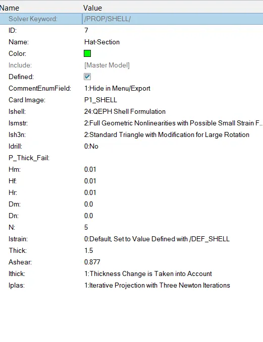
Similarly for close-out_panel.
The run time and animation save steps are kept same to enable comaprison studies
Simulation is started by
Analysis panel -> Radioss
Changing input file to changed_0000.rad and copying and renaming Elemental_Formulation_Shell-3_Assignment_0001.rad to changed_0001.rad file in different folder.
Here export options -> all
run option -> analysis
run number -> 1 and option space -> -nt 4 and starting Radioss
By doing this new window opens showing the simulation steps and it continues.

Here Energy error is 0.1 % which is less than 5% so results are good and acceptable
Results:
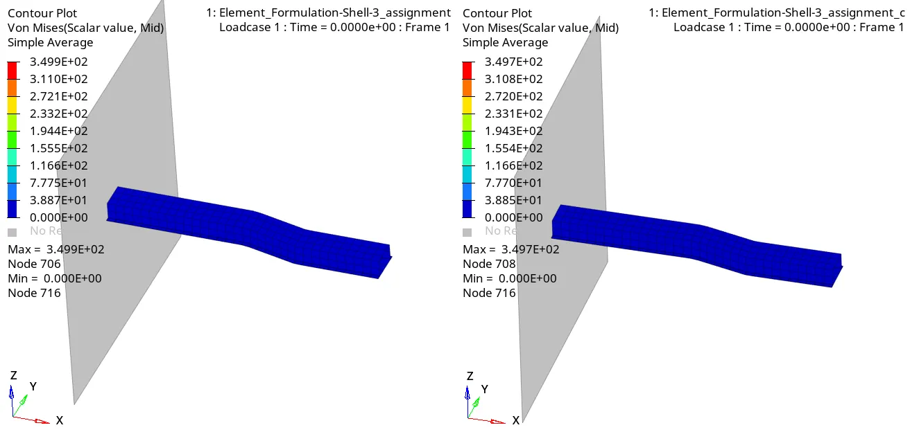
The animations file shows von mises stress of the files of different parameters are taken by importing h3d files into Hyperview and switching on contour plot for von mises stres with simple average method.
The graph plots are taken from Hypergraph 2D importing T01 files
Selecting Rigid Walls -> 4 Rigid wall 1 -> Total Resulatant force
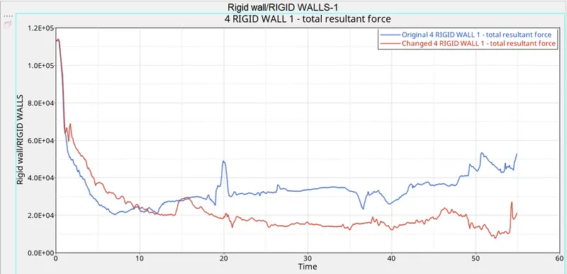
The resultant forces of changed model are less compared to original model and the fluctuations are also less as the QEPH method to deal with hourglassing is more stable.
Selecting Global variables -> Internal Energy -> MAG
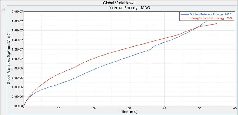
Here the internal energy of the original method increases linearly but the internal energy of the changed model first increase and then began to stabilize due to switching the geometric non linearities when considering strains.
Selecting Global variables -> Horglass Energy -> MAG
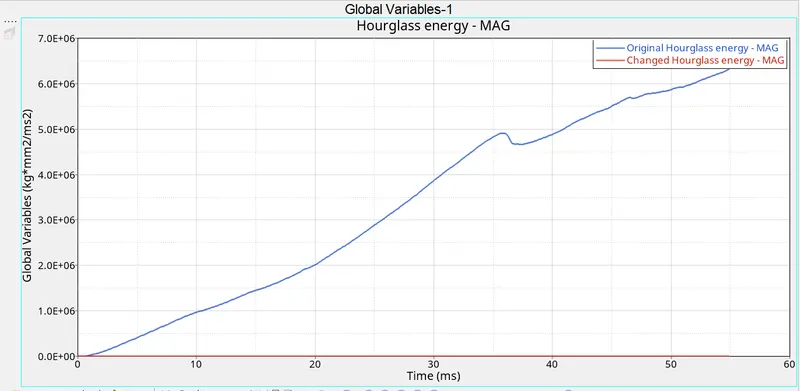
The results from graph shows the hourgalss energy is zero when properties are changed to recommended, when compared to the hourglass energy when properties are kept as they were:
QEPH is taken with 5 integration points instead of 1 taken for Q4 method so the results are stable and accuracy for changed properties simulation is high.
This is due the Ishell chosen for original is 1 (Q4) which is default an this uses pertubation method to control hourgalss energy where external energy is taken to stabilize it, so the hourglass energy is high.
Whereas for changed simulation Ishell is taken as 24 (QEPH) which uses physical stabilization method, which reduces houglass energy to minimum as it is applied on material level, so the value is very close to zero.
Selecting Global variables -> Contact Energy -> MAG

The contact energy is high in the original model compared to changed model, this is due to Istrain where geometric non linearities is activated which accur in crash simulations.
Selecting Global variables -> Total Energy -> MAG
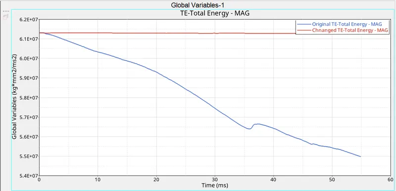
This decrease in total energy is due to huge hourglass energy which is energy loss in the original model when compared to almost no hourglass energy which is no energy loss.
Hourglass Energy:
This Hourgalss energy is energy required to stabilize the deformation of elements, which occurs but no energy change is detected which causes this deformation.
Hourglassing occurs due to Reduced integration where instead of having 4 integration points we use only one and also when solid elements having only one thickness integration points.
There are two ways to control this formation of Hourglass.
1. Peturbation (Viscous method) for Ishell = Q4 elements
2. Physical stabilization (Stiffness method) for Ishell = QEPH Elements
Both this Q4 and QEPH used reduced intergration points
Viscous Method:
Here the deformation is detected with relation motion of the nodes and when deformation is detected, force is applied aditionally on the relative nodes to offset this deformation and stabilizes the formation of this deformation.
This force applied externally introduces an energy which is called Hourglass energy and this force is defined on elemental stiffness an this stiffness is external.
This hourgalss energy is loss of energy.
Stiffness method:
Stiffness is artificially added to the element and so material properties are affected.
This addted stiffnes depends on natural tangent modulus of the material.
Here the hourglasses are controlled even before they appear. Since here the contolling is done in material level the hourglass energy is very less.
This stiffness introduced artificially may stiffen the element affects the performance and to minimize this effect the hourglass coefficient changed from 0.1 to 0.03.
This hourglass depends on material natural yield