Assignment 3
OBJECTIVE - Comparison of results with base simulation and improved shell element properties by creating various plot graph and run simulation by using hyperwork .
PROCEDURE -
CASE - 1 BASE SIMULATION.
1. First import the starter file 0000.RAD in hypermesh under radioss profile. Now using the crash beam file from the previous assignment, change the run time to 55 ms.
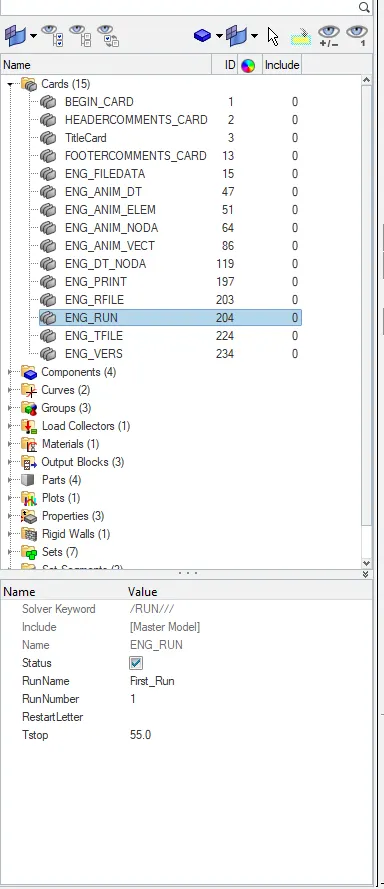
2. Now change the number of animation steps during simulation to a minimum of 25 and maximum of 60.
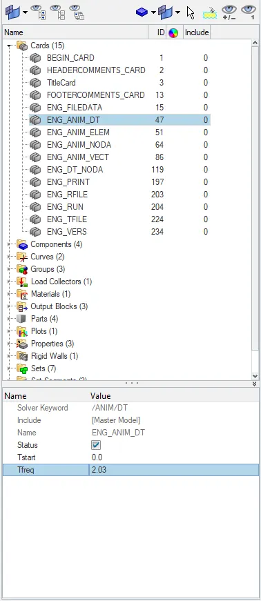
so for 28 number of animation step the frequency will be
T freq = 55/28 = 2.03
now go under ENG_ANIM_DT, change the T freq = 2.03
3. Now Run the base simulation without any modification to element properties. To run the simulation, go to under Analysis - Radioss - Input file - Provide path where data to be stored - Click on radioss.
the generated output file will be stored in the file location provided.
4. After the completion of simulation The energy error and mass error can be checked by going to the output file location.
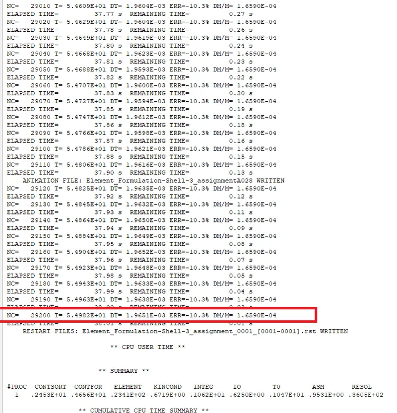
it can be seen that energy error is -10.3% and the mass error is 1.6590E-04 and for energy error the acceptable range is upto - 15%. so the obtained error are in acceptable range.
5. Since the error are in acceptable range required simulation can be generated by go to hyperview GUI and in Hyperview load the (H3D) file generate from the simulation.
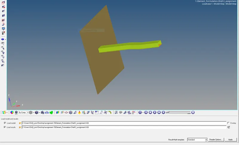
To obtain the required plot graph split the GUI and select Hypergraph 2D and in the data file load the T01 file obtained from the simulation.
Select X type = Time, Y type = global variables, Y Request = internal energy, hourglass energy, contact energy and total energy, Y Component = MAG and click on apply.
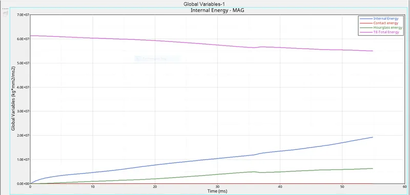
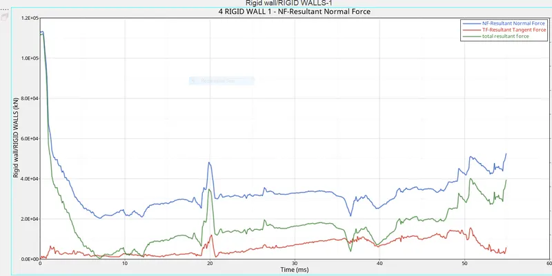
For the rigid wall forces graph , select X type = time, Y type = Rigidwall/RIGIDWALLS , Y request = 4 RIGID WALL 1 ,Y component = NF- Resultant Normal Force , TF - Resultant tangent force and total resultant force.
CASE - 2 After change the shell elements properties.
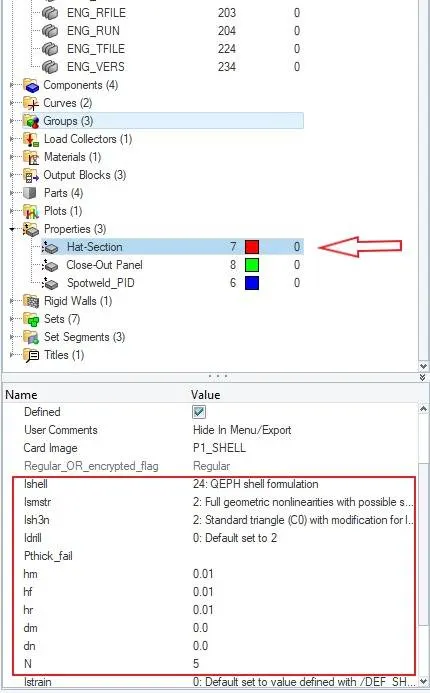
6. Now change the shell elements properties to Recommended properties and save this as seperated RAD file and run the simulation.
Recommended properties:
| Parameters | Comment | |
|
Ishell =24 |
QEPH 4 nodes shells are best combination of cost and accuracy. | |
|
Ismstr=2 |
Full geometric nonlinearities (default)with possible small strain formulation activation in RADIOSS Engine. | |
|
Ish3n=2 |
Standard 3 noded shell (C0)with modification for large rotation(default) |
|
| N=5 | Number of integration points set to 5 for accuracy bending. | |
|
Ithick=1 |
Thickness change is taken into account for accuracy. |
|
|
Iplas=1 |
Iterative plasticity for good accuracy. |
Now change the parameters in the property card in close out panel and hat section.
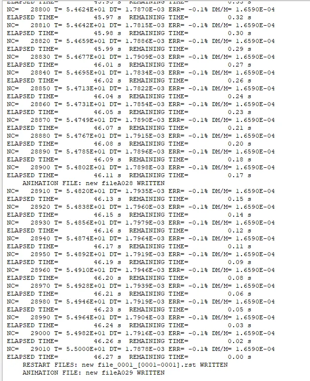
Now Run the simulation and after completion of simulation , the energy error and mass error can be checked by going to the output file location.
it can be seen that energy error is -0.1% and the mass error is 1.6590E-04 .
To obtain the required plot graph split the GUI and select Hypergraph 2D and in the data file load the T01 file obtained from the simulation.
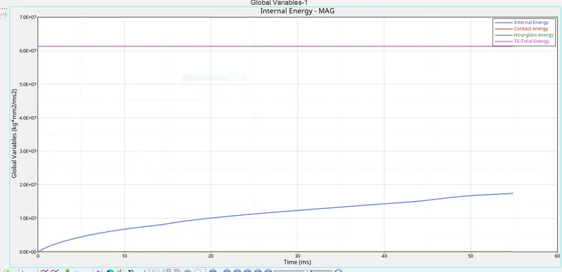
Select X type = Time, Y type = global variables, Y Request = internal energy, hourglass energy, contact energy and total energy, Y Component = MAG and click on apply.
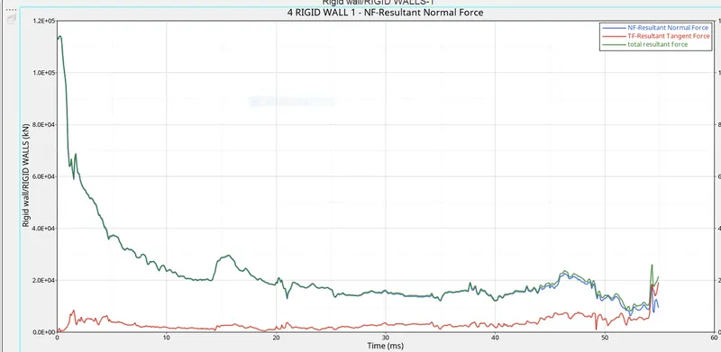
For the rigid wall forces graph , select X type = time, Y type = Rigidwall/RIGIDWALLS , Y request = 4 RIGID WALL 1 ,Y component = NF- Resultant Normal Force , TF - Resultant tangent force and total resultant force.
 \
\
8. Now compare the result of both the simulations, whether there is any changesin the result and why there is change in result if there.
Energy error-
It is observed that in case 1 the loss of energy error % is -10.3% while when we change the property parameter in case 2 the loss of energy % is -0.1% which will gives us to better accuracy in result.
Mass error -
It is observed that in both the cases mass error is same .
Total energy -
In case 1 the total energy decrease as time increases while in case 2 Total energy remain constant because in case 1 energy dissipiation is more due to hourglass effect while in case 2 when we improved the property parameter and used of QEPH element the hourglass effect is zero so total energy remain constant.
Hourglass energy -
Hourglass energy increase as time increase in case 1 while in case 2 hourglass energy remains zero because hourglass energy is treated at the material level and oppose the velocity of node but not the force that is why when force is introduce we add some stiffness and that stiffness going to be controlled the hourglass energy. here we changing shell parameter as QEPH shell and it is use physicalstabilization method to fixed hourglass deformation ,that why there is no hourglass created.
Contact energy - Its nearly zero in both the cases.
Internal energy - Internal energy in both the cases is nearly constant and increase with the increase in time because when the beam crash with rigidwall some energy of the kinetic energy is change into heat and thus increase the internal energy and also it depend other factor also like material properties.
Normal forces - Normal force is applied onto a rigid wall during simulation higher in both the cases when beam hit with rigid wall and then decreases as simulation progress . much of normal forces are converted into frictional forces. this forces are plotted along with resultant forces.
9. Explanation on hourglass energy and its causes and the step to avoid it.
Hourglass modes are nonphysical modes of deformation that occur in underintegrated elements and produce no stress. It is essentially a spurious deformation mode of a Finite Element Mesh, resulting from the excitation of zero-energy degrees of freedom. It typically manifests as a patchwork of zig-zag or hourglass like element shapes , where individual elements are severely deformed, while the overall mesh section is undeformed. This happens on hexahedral 3D solid reduced integration elements and on the respective tetrahedral 3D shell elements and 2D solid elements.
Two method used to control the formation of hourglass energy.
1. perturbation (Q4 element)/ Viscous method - The method is used by the solver when the hourglass deformation mode is detected with the relative velocity of the nodes. A Damping force is applied to oppose this velocity. This result in addition to stiffness to the element and the deformation is then stabilized. this forces introduces an artificial energy named as hourglass energy .
this method is used for high velocity/ high strain rate problems.
2. Physical stabilization / stiffness method (QEPH) - this method works on a material level. hourglass loading depends on natural tangent modulus and the stiffness is added to the material.
QEPH is also able to reduce total accumulated hourglass deformation and is prefered for low strain rate problem. its the best method in term cost and accuracy.
CONCLUSION - The energy error decreases from - 10.3% to 0.1% after changes the material property and the hourglass energy is zero after apllying improved shell element property.