Assignment 2-RADIOSS Engine File Editing & 3D Meshing Challenge
Aim
To edite Engine file and generate 3D meshing with given parameter
Objective
- To check the materials properties of the rail component and calculate the speed of sound in steel rail
- To calculate the time taken for a shock wave to travel from one end of the rail to other of length of 1000 mm
- To Edit engine file so that the stress wave can be monitored, moving from one end of the rail to the other during impact
- To set the frequency of animation output to a time that will give 20 animation steps
- To perform 3D meshing(TETRA and HEXA mesh) with given quality parameter.
Procedure
Importing and reading Radioss starter files
1. To calulate the speed of sound in steel rail.
we have to see the material properties, to see the materials properties, Import the starter file and check the material propeties.
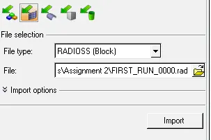
Open Hypermesh software, change the profile to Radioss, go to file import-> select import solver deck-> select the starter file, in our case, the given file name is FIRST_RUN_0000.rad as shown below
After importing the components, we can see the Rail cpmponents in graphical area. By clicking on materials, material properties can be seen as shown below
To calulate the speed of sound in steel rail, we have formula
c=`root`(E/`rho`)
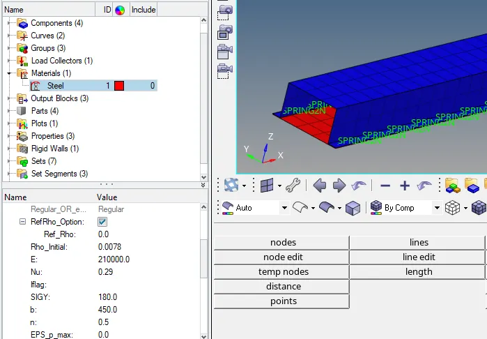
From above material properties
Young's Modulus of Rail steel materials E = 210000 N/mm^2
Density of Rail steel materials `rho` = 0.0078 g/mm^3
`therefore` Speed of sound in Rail, c = `root`(210000/0.0078) = 5188.745 mm/ms or (m/s)
2. The length of the rail is about 1000 mm. calculate the time takes for a shock wave to travel from one end of the rail to other.
The time takes for a shock wave to travel from one end of the rail to other is given by
t = `l`/c
`therefore` t = 1000/5188.745=0.1927 ms
3 Time for sound to travel length of rail is 0.1927 ms
4 Set the frequency of animation output to a time that will give 20 animation steps(ANIM/DT)
Animation frequency = 0.1927/20=0.009636 ms
5 Edit the Engine file so that the stress wave can be monitored, moving from one end of the rail to the other during impact- this will required a termination time equal to the time taken for the sound to travel the length of the rail(set on Run card)
Now we will open Radioss Engine file in notepad. file name as FIRST_RUN_0001.rad. identify and edit the termination time and animation frequency
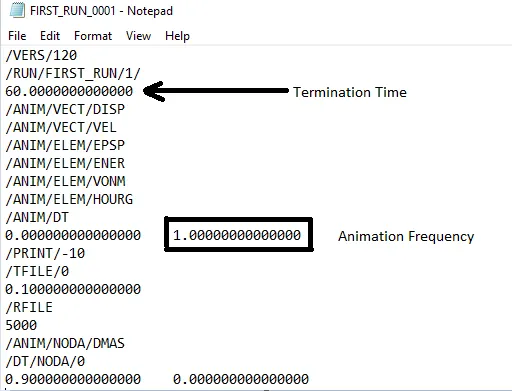
change the value of termination time and animation frequency as per Calculated value
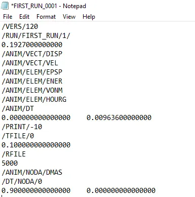
After Substituting the value save the Engine file.
Tetra meshing
Import the Geometry (Housing component) in HyperWork software
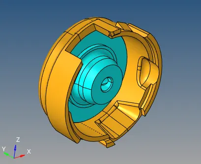
After importing geometry, the primary stage of meshing any part is to clean the geometry, if the part created in any modeling software and then imported in any CAE software due to change in the formate of the file. some error in the geometry can be seen like Free egdes, deformed shape, duplicate surface, missing surface, unconnected adjection surface so on and so forth but in these can there is no any damage surface, so we can proceed for 3D meshing
There are 3 different Approach to generate 3D mesh(for Tetra Mesh)
- Conversion of 2D tria mesh to 3D tetrahedral mesh using tetra mesh panel
- Volume tetra mesh panel
- Quick tetra mesh from utility panel
For hub model we will generate tetra mesh using Quck tetra mesh from utility panel
Go to View-> browsers->Hypermesh->utility than Geo/mesh click on quick tetra mesh select the component and enter mesh size and mesh type and click on mesh after generating tetra mesh some tetra collapse elements are present, than can be solve by translate or remesh command.
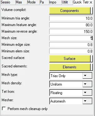
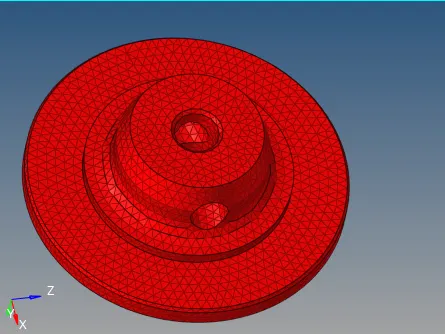
To check tetra collapse elements go to tool->check elements->3d->tet collapse

Housing model
Volume method is used to generate tetra mesh on this model. Go to 3D mesh panel->Volume mesh assign mesh parameter select the component and enter mesh size click on mesh after generating tetra mesh some tetra collapse elements are present, than can be solve by translate or remesh command.

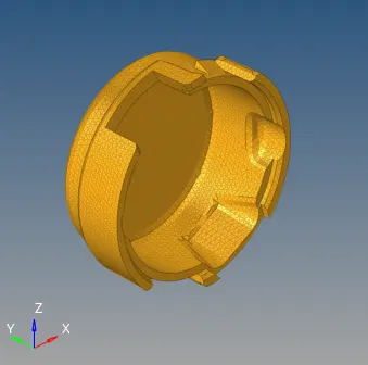
To check tetra collapse elements go to tool->check elements->3d->tet collapse

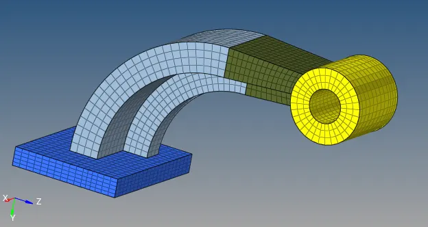
Hexa Meshing on Arm Bracket
As usual import the geometry, after importing the model in hypermesh. we will check for any surface defeats in the model. in this case there were no any surface damage so we will proceed for meshing. there are 4 parts base, arm curve, arm straight and boss. first of all we will mesh base with quad element with mesh size of 10

After 2D mesh on upper surface of base component it time to do 3D mesh on it. Go to 3D -> select line drag command to perform hexa mesh
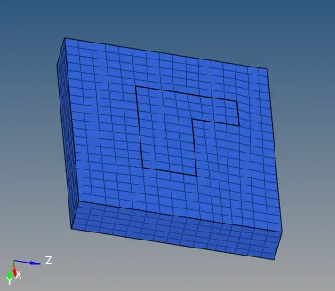
since we have surface mesh on arm surface of the base. make centroid node by selecting nodes command. now we can spin the elements to obtain 3D Hexa mesh here under spin command enter angle as 90 degree on spin as 25 amd select x-axis as our rotation axia and base point as created centroid node.

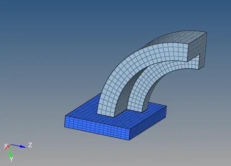
Now we will mesh the arm straight part which is connected with arm curve. used face tool to create 2D shell elements on 3D Hexa mesh, we will create 2D mesh insucha way that the nodes and elements are eactly corresponding to the opposite face.then we will used linear solid command in 3D panel.

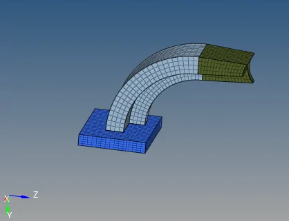
for boss part we will mesh this with solid map command. create 2D mesh on the plane surface than we will navigate to general sub panelunder solid map in 3D.
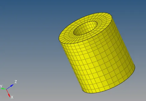
At the end we will delete all the 2D shell and temp nodes.
Final model
Learning outcomes
Able to understand
- Importance of starter and engine file in Radioss
- To edit Engine file and check the materials property parameter from starter file in Radioss
- Generating Tetramesh with different approach
- Generate HEXA mesh with different commands
Conclusion
The speed of sound in steel and times taken by the sound wave to travel through the length of the steel rail has calculated. And also Termination and animation frequency is determined and edited on engine. The 3D meshing (TETRA and HEXA ) is generated with the required quality.