Assignment 2-RADIOSS Engine File Editing & 3D Meshing Challenge
Objective:
Questions:
1. Check the material properties of the rail component and calculate the speed of sound in steel rail=______
2. The length of the rail is about 1000 mm. Calculate the time takes for a shock wave to travel from one end of the rail to the other.
3.Time for sound to travel length of rail=______
4.Edit the engine file so that the stress wave can be monitored, moving from one end of the rail to the other during impact -this will require a termination time equal to the time it takes for the sound to travel the length of the rail (set on/RUN card)
5.Set the frequency of animation output to a time that will give 20 animation steps(/ANIM/DT)
6.Change /print -10.
7.3d meshing tetra mesh and hex mesh
- Repeat class examples and, maintain the quality.
- Target tet size=5mm, hex size=10mm, tet collapse=0.15.
Procedure:
1.Check the material properties of the rail component and calculate the speed of sound in steel rail=_______
Import the FIRST_RUN_0000.rad in the Solver deck of Radioss profile of Hypermesh.
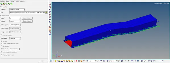
Speed of Sound = `√(E/(ρ))`, E (Young’s Modulus) and (density) is taken from the properties (material -steel) from the file.
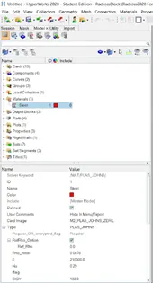
E = 210000 `(g (mm) /(ms)^2) / (mm)^2`
ρ = 0.0078 g/mm3
Speed of sound =`√(210000/0.0078)` = 5188 mm/ms
2.The length of the rail is about 1000 mm. Calculate the time takes for a shock wave to travel from one end of the rail to the other.
Distance = Length = 1000 mm, Speed = 5188 mm/ms
Time =`(Distance)/ (Speed)` = `(1000m )/(5188 (mm)/(ms)`= 0.192725 ms
3.Time for sound to travel length of rail=______
Length of Rail is 1000 mm, so the time for sound to travel the length of rail = 0.192725 ms
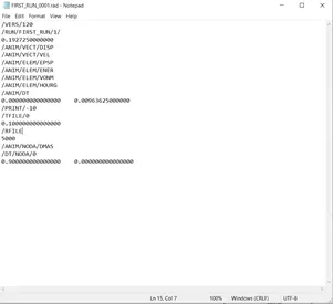
4.Edit the engine file so that the stress wave can be monitored, moving from one end of the rail to the other during impact -this will require a termination time equal to the time it takes for the sound to travel the length of the rail (set on/RUN card)
Edit the time in the FIRST_RUN_0001.rad file as 0.192725 ms and run it, it will automatically change the Tstop value of ENG_RUN.
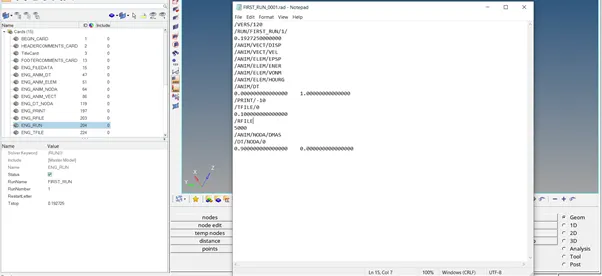
5.Set the frequency of animation output to a time that will give 20 animation steps(/ANIM/DT)
Frequency = `(Time )/ (Steps )` = `0.192725/20` = 0.00963625
Edit the frequency in the FIRST_RUN_0001.rad file as 0.00963625 ms and run it, it will automatically change the Tfreq value of ENG_ANIM_DT.
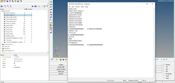
6.Change /print -10.
- 3d meshing tetra mesh and hex mesh
- Repeat class examples and, maintain the quality.
- Target tet size=5mm, hex size=10mm, tet collapse=0.15.
1.Import/open the component in hypermesh window, using import geometry (STEP for Housing) and delete the Solids if any before meshing. Check for the geometry Cleanup.
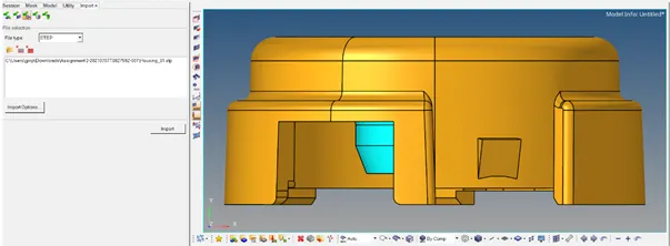
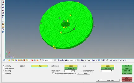
2.Mesh the inner component of the Housing model, with trias of elements 5 mm.
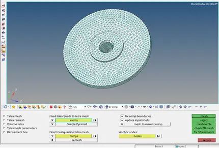
3. In the 3D panel – tetramesh, select the 2D tria meshed elements under the fixed trias/quads to tetra mesh option, and then mesh it to create the 3D tera mesh elements on the component.
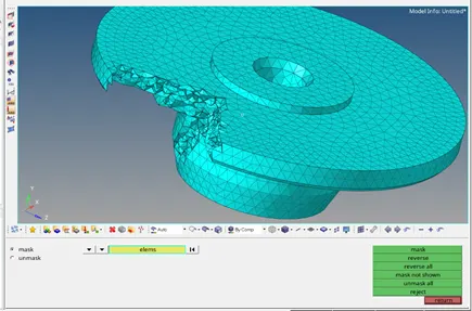
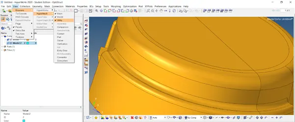
4.Switch on the Utility view from the menu bar (View – Browser – Hypermesh – Utility), in Geom/Mesh select Quick TetraMesh. Select Components, Surfaces to be meshed by specifying mesh size and mesh type as Trias only and then mesh it.
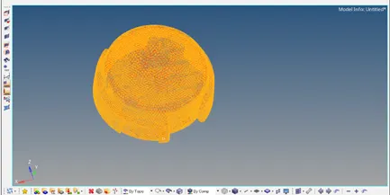
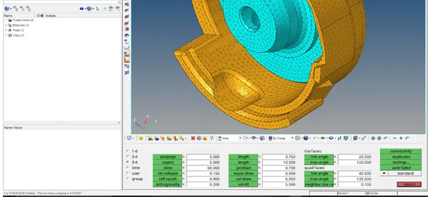
5. Now check the 3D tetra elements satisfy the given criteria, in the Check elems – 3D of the Tools panel, i.e., (Tet Collapse = 0.15) and save the failed elements, Now isolate the failed elements, using mask – select elements (retrieve) mask – reverse. and now remesh the failed elements, using Tetramesh – Tetra remesh selecting the failed elements (unmask the adjacent elements) after altering the tetra mesh parameters according to the criteria (size, Tet collapse).
Final Model Image:
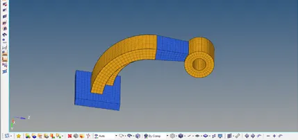
6.Import the component (Arm_Bracket) using import geometry -STEP
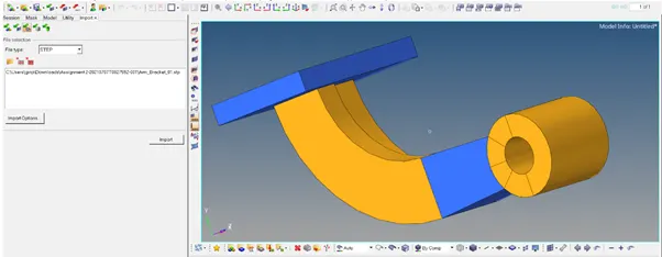
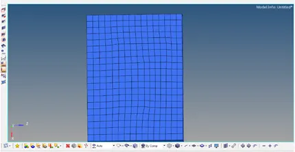
7.Mesh the upper surface of Model 1 in the component with mesh size 10 and type mixed.
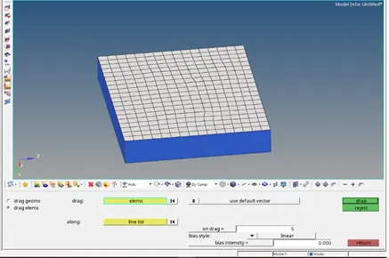
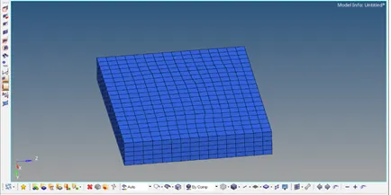
8.Using Drag option in the 3D panel, Select the 2d meshed elements with element size 5 and select one short edge in along line list to create the 3D elements for Model 1.
9.To mesh the Curve section (Model 3) of the component, create the centre using the Three-point of the Distance option in the Geom panel.
Then, select the 2d elements of model 2 and using the spin option in the 3D panel giving the angle 90 deg, along the x-axis and select the centre to spin as a base, 3D elements for model 3 is created
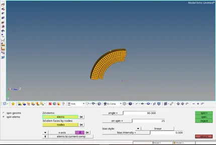
10.To mesh model 4, using the face option of the Tool panel outer face of model 3 attached to model 4, 2d shell elements are created, and then the opposite side of model 4 has equally meshed with 2d shell elements of size 10 and mixed type.
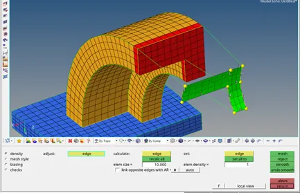
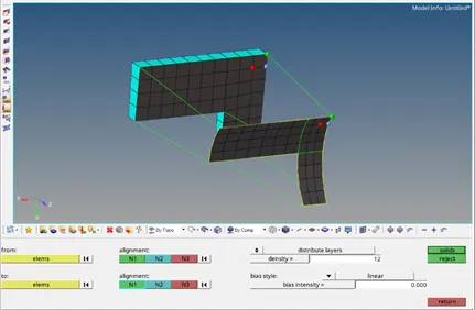
11.Using linear solid option of 3D panel, both shell elements are selected (from and to) and their orientation also selected, giving density as 12, 3D elements are created for model 4.
12.For meshing Model 5, mesh the one base surface of the boss and using the solid map tool of 3D panel, Select the dest surface as unmeshed surface, elements to drag as 2d shell elements of the meshed surface and along the node path, select the nodes of the 3D elements of model 4 to create the 3D elements for the boss.
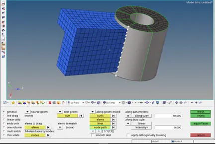
13. Organize the 3D elements according to the model of the components and delete the 2D shell elements using delete by config (QUAD).
Final Model Image:
Conclusion:
Thus, we meshed the components using Tetra and Hexa 3D elements accordingly, using suitable methods.
Learning Outcome:
Basics of starter and engine file of Radioss
3D meshing (Tetra & Hexa) using various methods.