Assignment 2-RADIOSS Engine File Editing & 3D Meshing Challenge
OBJECTIVE :
- To determine the steel rail's sound speed and examine the component's material qualities.
- To determine how long it takes a shock wave to travel a distance of 1000 mm from one end of the rail to the other.
- In order to track the stress wave as it moves from one end of the rail to the other during impact, the engine file must be edited.
- To adjust the animation output frequency so that the engine file contains 20 animation steps.
to mesh the components in three dimensions using the specified quality settings.
Reading and importing the RADIOSS Starter file to respond to the following questions:
We must first examine the rail component's material qualities. There are two methods available for examining the material qualities. Importing the file into Radioss and looking up the material attributes is one method. Thus, after the Hypermesh is open, we will select RADIOSS as our user profile. Next, we'll open Radioss and import the starting file. We will import FIRST_RUN_0000.rad, the file that is provided in our instance, using the Import Solver Deck browser.
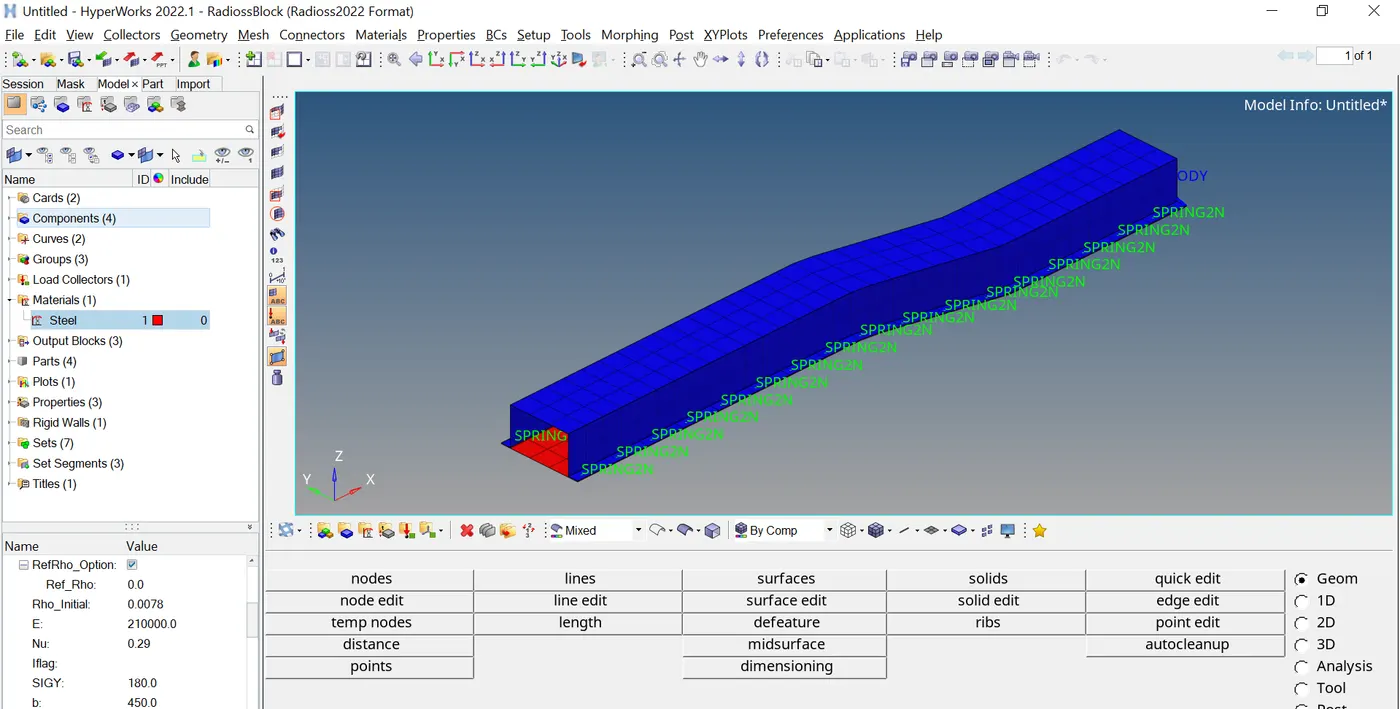
Next, we'll select the Import command. The Rail component is shown in the Hypermesh Graphics section when the component has been imported. Now, we can use the following formula to get the sound speed in a steel rail:
c=√E/rho
where is density, E is Young's modulus, and c is the speed of sound. Therefore, we will require the rail component's E and ρ values based on the formula. These settings for the Rail component are available in the model's Material Properties, as indicated below.
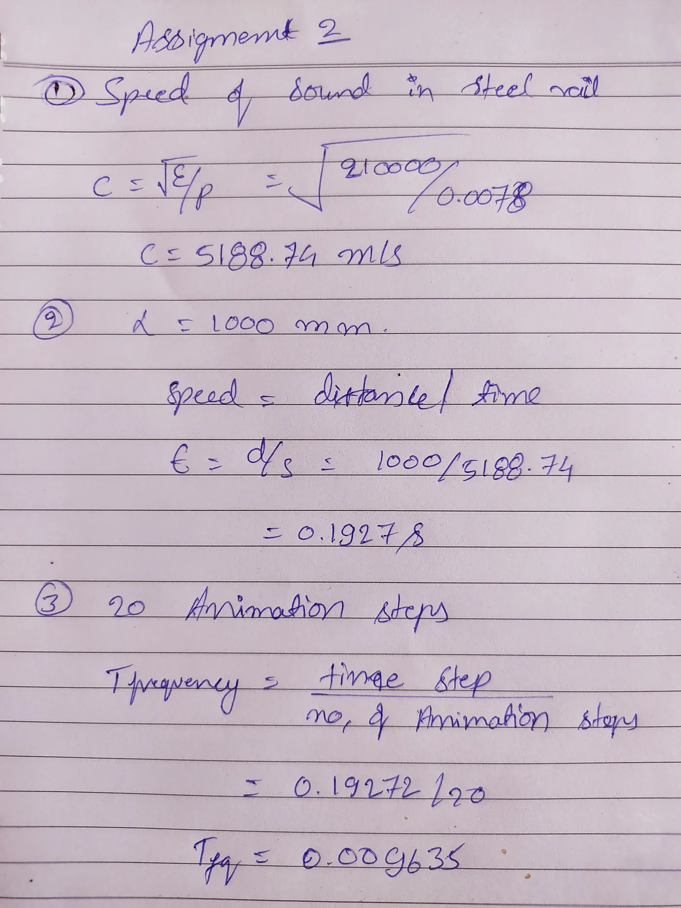
In steel rail, the sound speed is thus 5188.7452 m/s, or 5188.7452 mm/ms.
Sound travels the length of a rail in 0.1927 milliseconds.
Thus, it is necessary to record the animation every 0.009635 milliseconds.
These values now need to be included into the Engine file. By entering these values directly into the Engine file, we may do this.
Editing RADIOSS Engine Files in Notepad
The FIRST_RUN_0001.rad file will be opened in Notepad. The settings for the animation frequency and termination time must be determined and changed in this instance.
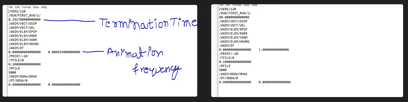
Following their identification, we will change them by entering the animation frequency and termination time values that we determined through computations.
3D MESHING :
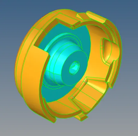
1. Housing Model (Tetramesh) – The given model is as follows,
In order to do geometry cleanup after importing the model into Hypermesh, we will search for surface flaws in the model. We will move forward with meshing as the model had no surface flaws. The hub and cover are the model's two constituent parts. So, one by one, we shall mesh them. Tetra meshing can be generated using the three main approaches listed below:
Tetrahedral elements are created from 2D tria using a Tetra Mesh panel.
Making use of the Utility panel's Quick Tetra Mesh.
With a Tetramesh panel for volume.
Therefore, we will use the first way of meshing—that is, transforming 2D tria into 3D tetra elements—for the hub component. We'll set the hub component as the active component, hide the other components, and use the shortcut key F12 to access the 2D Automesh panel. In this case, we'll pick the surfaces that are visible and input 5 mm as the goal element size. The most crucial step is to click on mesh after selecting trais alone as the mesh type. We must transform the 2D tria components that were created on the hub into 3D tetra elements. To do this, navigate to the 3D page's Tetramesh panel and choose the 2D tria components under Fixed trias/quads to Tetra mesh option. Here, we've kept the tet collapse criterion at >0.15, which we'll set in the Tetramesh parameters sub-panel before meshing.
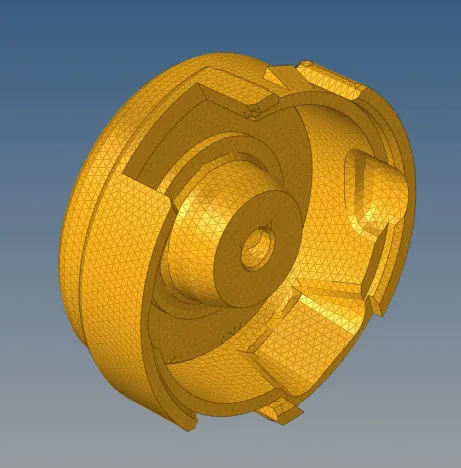
The items in the Tetramesh sub-panel can now be meshes. As a result, the model will be used to construct the 3D tetra mesh. We will mask some parts in the mask panel and validate in order to confirm the 3D mesh. We will use the F10 shortcut key to travel to the elements panel and check for tet collapse in the 3D sub-panel in order to determine the tet collapse criterion. Here, we have zero elements failing in tet collapse since we set the tet collapse threshold in the Tetramesh panel to be larger than 0.15 before meshing. Thus, the hub component's meshing outcome.
We will now mesh the cover component in three dimensions. We'll use it as our primary component going forward and conceal the others. This component will be meshed using the third technique, Volume Tetramesh. Thus, we will browse to the Tetramesh panel's Volume Tetra sub-panel on the 3D page. Here, we will choose one of the surfaces that are offered, enter element size as 5, and then click mesh. This feature will produce three-dimensional tetras inside the component's contained volume. We shall now look for the Tet collapse criterion once more. We have zero elements failing in tet collapse since we set the tet collapse threshold in the Tetramesh panel to be larger than 0.15 before meshing.
The 2D tria pieces that we previously created on the hub component will be deleted at the conclusion. To accomplish this, use the F2 shortcut key to get to the delete panel. Here, we'll pick items using the configuration as tria3, then click on the shown select entities. By doing this, every 2D tria element will be chosen. After that, we can select the delete entity option to remove every 2D tria from our model and leave only 3D tetras.
2. Arm Bracket (Hexamesh) – The given model is as follows,
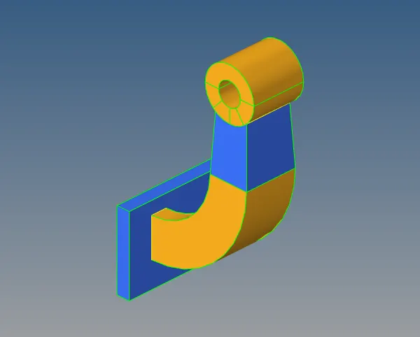
In order to do geometry cleanup after importing the model into Hypermesh, we will search for surface flaws in the model. We will move forward with meshing as the model had no surface flaws. The base, arm curve, arm straight, and boss are the four parts of the model. So, one by one, we shall mesh them. We will mesh the base component first as meshing the other three components can be helpful later on. We'll use it as our primary component going forward and conceal the others. We will pick the mesh type as mixed and generate a 2D mesh on the top surface of the base component. In other words, we shall produce every 2D quad element on the surface.
We shall offset these elements in order to transform them to 3D hexa elements. So let's navigate to the 3D page's element offset panel. Here, we will choose the 2D elements to offset from the solid layers panel. We will then click on the offset command after mentioning the number of layers (5 in this case) and total thickness (25 in this case). By offsetting the 2D components in 5 layers to a thickness of 25, this will produce 3D hexa elements.
Since the base component contains the imprint topology of the arm_curve component, we will now mesh the arm_curve component that connects the base. We'll use it as our primary component going forward and conceal the others. This component's geometry resembles a partial Torus. In order to create a 3D hexa mesh, we can spin the pieces. Thus, we will browse to the 3D page's spin panel. We will choose the 2D elements from the imprint area here under the spin elems sub-panel, input 90 for the angle, 25 for the spin, and choose the x-axis as our rotation axis. Using the F4 shortcut key, we will browse to the distance panel for the base point and use the three nodes option to build a center node. The elements will be spun using the spin option once this center node serves as the basis point. As a result, 25 layers of 3D hexa elements will be produced following the geometric profile.
We will now mesh the arm_straight component, which connects the arm_curve. Since the geometry of this component is tapered, we will create a 3D mesh using the linear solid command. To make a linear solid, we'll require two-dimensional faces or pieces. Thus, we will construct faces using the arm_curve component's 3D hexa components. To locate faces, scroll to the faces panel on the Tool page, select the arm_curve elements, and then click locate Faces. As a result, the arm_curve components will have faces. We will build a 2D mesh on the other tapering surface of the arm_straight component such that the nodes and elements precisely match the opposing face.
Next, we will navigate to the 3D page's linear solid panel. In this case, we will choose between elements, which are represented by the red face elements on the connecting surface of both components, and elements, which are represented by the blue tapered surface elements. After confirming that the nodes are aligned correctly, we will click on solids after setting the density to 12. By doing this, 12 layers of solid hexa elements joining the two meshes will be created. We will now remove the previously made faces to obtain the finished product.
We are going to mesh the Boss component now. Since we also need to link the mesh to the components of the arm_straight component, we may mesh this component using the generic solid map. Using project command, we will first project an outermost node to one of the component's planar surfaces. Next, we'll make a 2D mesh on the surface of the other plane. Next, on the 3D page, we will browse to the solid map panel's general sub-panel. The source geom will be set to none, the destination geom to the opposite surface, the elements to drag to be the 2D produced elements, the along geom to be the node route, and finally, mesh will be clicked. By doing this, 3D hexa components linking the arm_straight component's elements will be produced. These components will be kept in a brand-new part called solidmap. Using the arrange command, we will transfer these components to the boss component. The mesh is therefore as follows:
Lastly, we will remove every 2D shell component that is in the model. To accomplish this, use the F2 shortcut key to get to the delete panel. Here, we'll pick elements using the configuration as quad4, then click on the presented select entities. By doing this, every 2D quad element will be chosen. After that, we can select the delete entity option to remove every 2D quad from our model and leave just 3D hexa.
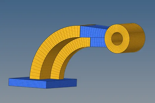
CONCLUSION :
It has been successfully estimated how fast sound travels in steel and how long it takes a sound wave to travel the whole length of a steel rail. By directly altering the.rad file, these computed values are provided as the animation output's termination time and frequency in the engine input file. Next, the necessary quality and mesh flow are achieved by employing the 3D solid elements (tetra and hexa) to mesh the two components (housing and arm bracket).