Assignment 2-RADIOSS Engine File Editing & 3D Meshing Challenge
Aim: To check the material properties of the Rail component and calculates the speed of the sound for the given component and perform Meshing operations for the given components
Objective :
- To check the Material Properties of the rail component and calculate the speed of sound in steel rail.
- To calculate the time takes for a shock wave to travel from one end of the rail to the other given that the length of the rail is 1000 mm.
- To edit the engine file so that the stress wave can be monitored, moving from one end of the rail to the other during impact.
- To set the frequency of animation output to a time that will give 20 animation steps in the engine file.
- To perform 3D meshing on the given components with given quality parameters.
Component 1:
Importing and reading the RADIOSS Starter file to answer the given Questions :
First, we have to check the material properties of the rail component. There are two multiple ways to check the material properties. One of the ways is to import the file in Radioss and check for the material properties. So after opening the Hypermesh, we will choose our user profile as RADIOSS. Then we will import the starter file into Radioss. In our case, the given file name is FIRST_RUN_0000.rad, we will import this file under the Import Solver Deck browser as shown below,
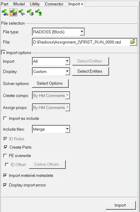
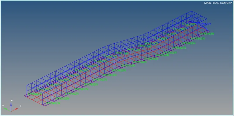
Once we click the import button corner of the above image, the Model will be displayed in the Hypermesh GUI.
We know that formula for calculating the Timestep of the Component.
c=√E/rho
Whereas,
C = Speed of the Sound
E = Young's Modulus of the material
Rho (ρ ) = Density of the material
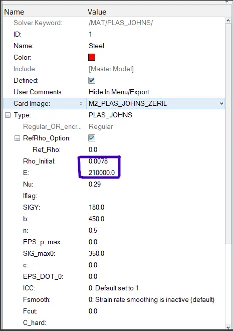
Material Property:
Workout:
c=√E/rho;
c=√210000/0.0078
c = 5,188.7452 m/s or 5,188.7452 mm/ms
Now we have to calculate Time-Step,
Speed = Distance/Time
5188.7452 = 1000/Time
Rearranging the equation:
Time = 1000/5188.7452 (mm/(mm/ms))
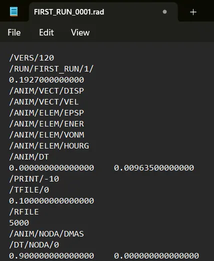
Time = 0.1927 ms
To find the Animation Steps:
T_Freq = TimeStep/Animation Frequency
T_Freq = 0.1927/20
T_freq = 0.009635
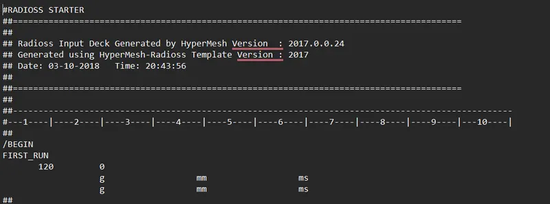
Units consideration:
Initial Engine File:
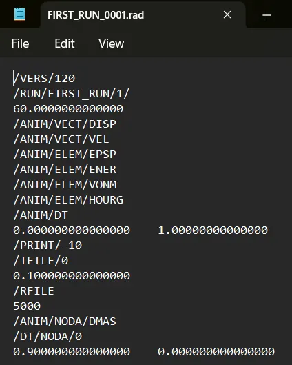
Final Engine File:
Component 2:
Creating of 1D element:
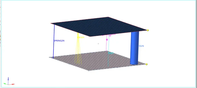
Here in the below component, I have recreated some 1-D Elements in the 2 plates.
I also assigned some properties such as Bar, Rod, and Beams.
Component 3:
Hub Housing:
- Conversion of 2D tria to Tetrahedral Elements, by using Tetra Mesh panel.
- Using the Quick Tetra Mesh from the Utility panel.
- Using Volume Tetramesh panel.
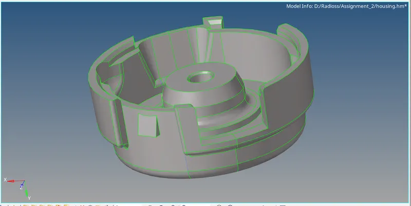
There are 2 components in the Hub Housing
- Hub
- Housing
1st Method:
HUB:
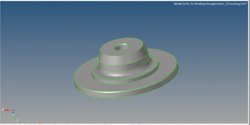
So for the Hub component, we will perform meshing by the first method i.e. converting 2D tria to 3D tetra elements. We will make the hub component our current component and hide other components and then navigate to the 2D Automesh panel by the F12 shortcut key. Here we will select the displayed surfaces and enter the value of the target element size as 5 mm. The important thing is we have to select the mesh type as trias only and click on a mesh. After creating 2D tria elements on the hub, we have to convert them to 3D tetra elements. For this, we will go to the tetra mesh panel on the 3D page where we will select the 2D tria elements under the Fixed trias/quads to tetra mesh option. Here, we have maintained tet collapse criteria as >0.15 which we will specify before meshing in the Tetramesh parameters sub-panel.
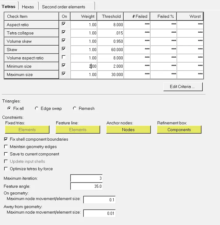
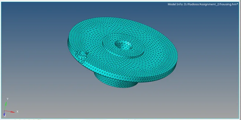
Now we can mesh the elements in Tetramesh sub-panel. Thus the 3D tetra mesh will be created on the model. To verify the 3D mesh, we will mask some elements in the mask panel and verify. To check for tet collapse criteria, we will navigate to the check elements panel by the F10 shortcut key and check for tet collapse in the 3d sub-panel. Here, as we specified the tet collapse criteria to be greater than 0.15 in the Tetramesh panel before meshing, we have zero elements failing in tet collapse. Thus the meshing result of the hub component is shown below.
2nd Method:
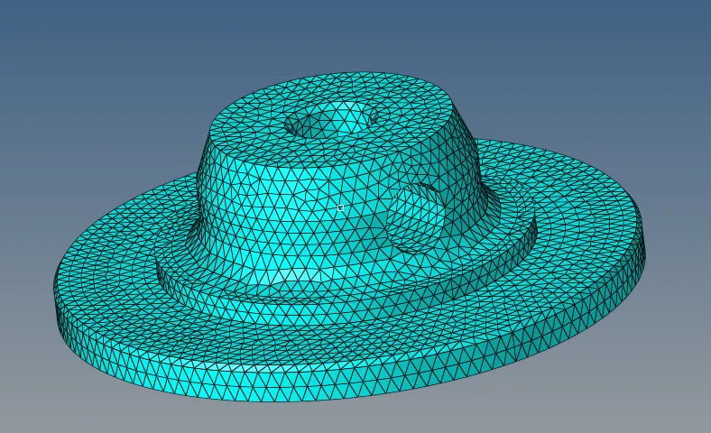
Now we will perform 3D meshing on the cover component. We will make it our current component and hide all other components. We will mesh this component by the third method i.e. Volume Tetramesh. So we will navigate to the Volume Tetra sub-panel under the Tetramesh panel on the 3D page. Here we will select the displayed surfaces, mention the element size as 5, and then we will click on the mesh. This feature will create 3D tetras in the enclosed volume of the component. Now we will again check for tet collapse criteria. As we specified the tet collapse criteria to be greater than 0.15 in the Tetramesh panel before meshing, we have zero elements failing in tet collapse. Thus the meshing result of the cover component is shown below,
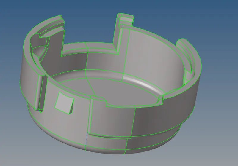
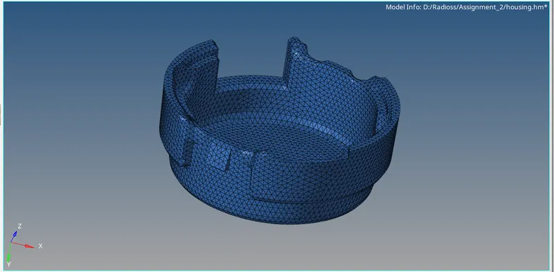
Component 4:
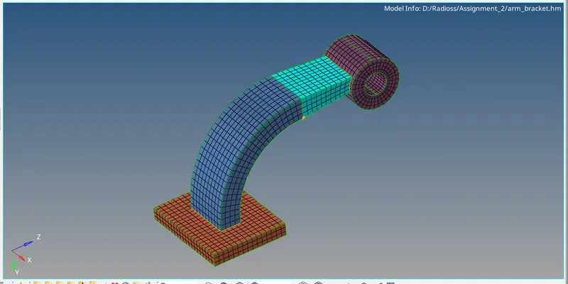
Arm Bracket:
If we have to do Hex mesh for these components.
After importing the model, we have to measure the size of each part, and according to that, we performed the mesh sizes.
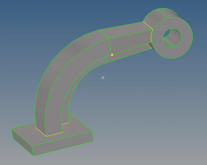
There are 4 parts to it
- Base
- Arm Curve
- Arm Straight
- Boss
Base:
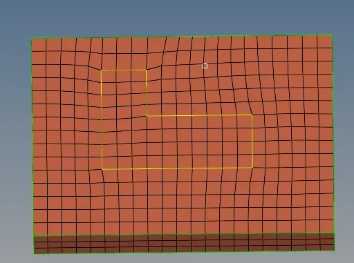
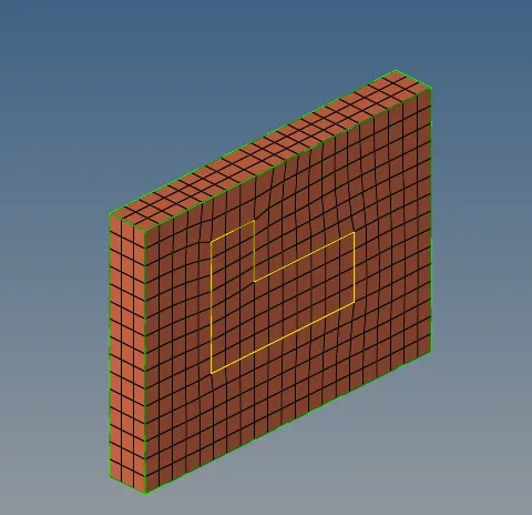
We have to mesh the part 2 times, Triple cons parts have to mesh once and the rest of the parts another time.
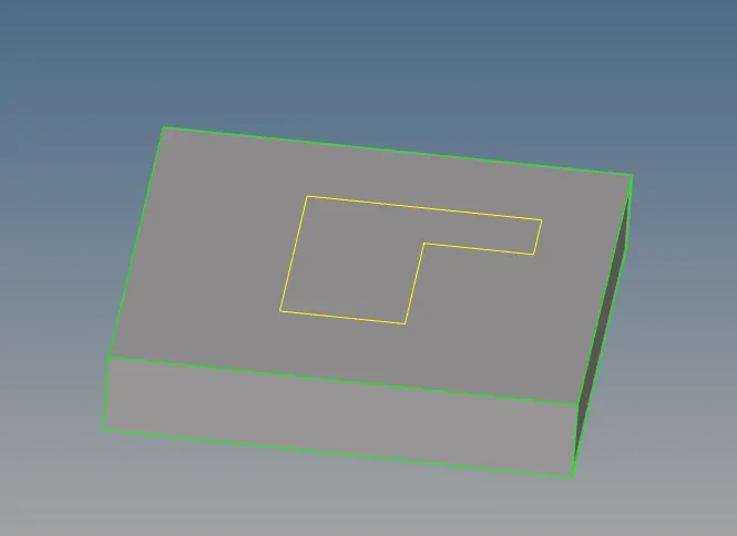
Slight deviation occurred in the triple cons, due to proper mesh flow.
Arm Curve:
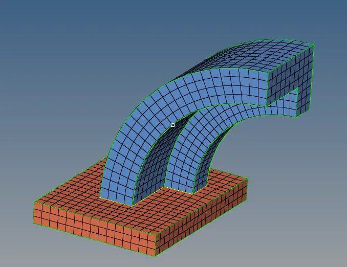
The Triple Cons parts are been stitched into curved parts, so we must follow the mesh through it.
Options are available in the 3D -> Solid Map
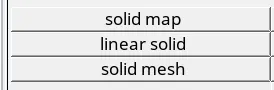
By using these multiple options, we can use and drag those mesh.

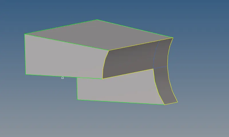
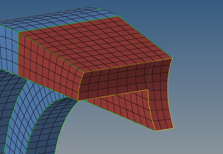
Arm Straight:
Boss:
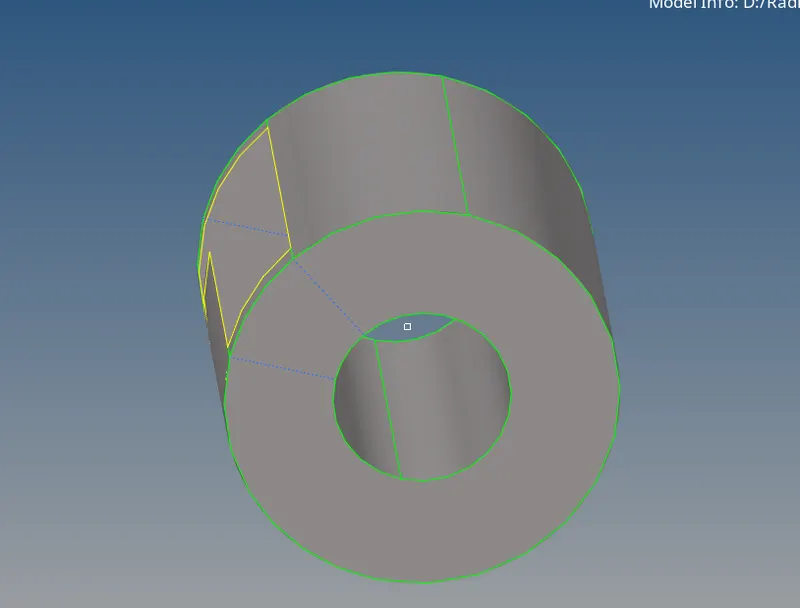
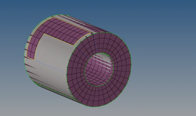
Final Output:
Outcomes:
Learned about the Engine File and mesh.
Conclusion:
Here I have calculated and updated the Time frequency by calculating.
Mesh of Tetra mesh and Hex mesh and also Creating of 1D elements is been done.