Assignment 2-RADIOSS Engine File Editing & 3D Meshing Challenge
AIM:
To determine the given challenge.
OBJECTIVE:
1. Check the material properties of the rail component and calculate the speed of sound in steel rail.
2. The length of the rail is about 1000 mm.calculate the time takes for a shock wave to travel from one end of the rail to the other.
3.Time for sound to travel length of rail.
4.Edit the engine file so that the stress wave can be monitored, moving from one end of the rail to the other during impact -this will require a termination time equal to the time it takes for the sound to travel the length of the rail(set on/RUN card)
5.Set the frequency of animation output to a time that will give 20 animation steps(/ANIM/DT)
6.Change /print -10.
7.3d meshing tetra mesh and hex mesh
- Repeat class examples and, maintain the quality.
- Target tet size=5mm,hex size=10mm,tet collapse=0.15.
PROCEDURE:
I. Check the material properties of the rail component and calculate the speed of sound in steel rail:
1.To check the material properties of the material of the rail component, we have to import the component in the hypermesh.
2.Go to the import option, there we are going to select the 0000.rad file and import it.
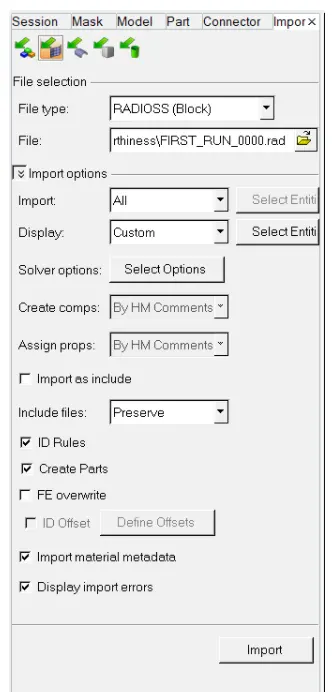
3.We will go to material property and check the values:
Speed of sound (c) = (E/P)^*1/2
where,
E = Young's Modulus
ρ = denstiy
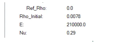
Speed of sound (c) = 5188.745 m/s.
2. The length of the rail is about 1000 mm.calculate the time takes for a shock wave to travel from one end of the rail to the other:
Shock wave travels at the speed of sound. So shock wave speed = speed of sound = 5188.745 m/s.
time(t) = Distance/speed of shock wave.
t = 1000/5188.745 = 0.1935s.
3.Time for sound to travel length of rail:
time(t) = Distance/speed of sound
t = 1000/5188.745 = 0.1935s.
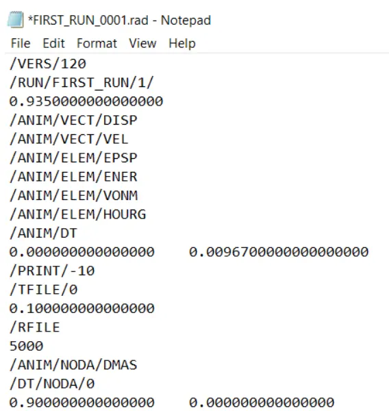
4.Edit the engine file so that the stress wave can be monitored, moving from one end of the rail to the other during impact -this will require a termination time equal to the time it takes for the sound to travel the length of the rail(set on/RUN card):
We have to give the end time to be 0.1935s. There is a way by that we can do that.
I. Open the 0001.rad file and edit the end time value in the file. And give the value.
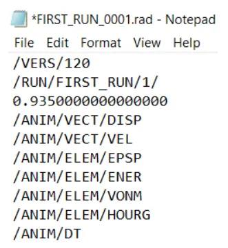
II. We can change the value in the hypermesh itself. There we go to the ENG_RUN card. There we change the Tstop value.
There we have to give the value to be 0.1935 and after that we have to run the file. So it will change the values in the 0001.rad file itself.
5.Set the frequency of animation output to a time that will give 20 animation steps(/ANIM/DT):
Frequency = time/no.of revolutions
= 0.1935/20
= 0.009675.
Open the 0000.1rad file and edit the end time value in the file. After given the value,
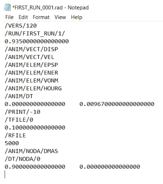
II. We can change the value in the hypermesh itself. There we go to the ENG_ANIM_DAT card. There we change the Tfreq value.
There we have to give the value to be 0.009675 and after that we have to run the file. So it will change the values in the 0001.rad file itself.
6.Change /print -10:
We can see that default PRINT value is 10. So there is no need to change that.
2.DEPLOYING THE 1-D ELEMENTS BETWEEN TWO PLATES:
1.1D elements are basically used to reduce the computaional time.
2.1D elements are also used to make connections between different components. If two components have to be connected but no geometry is available to mesh simply putting the 1D elements there would represent the connection. Thus no need for geometry is required in such cases.
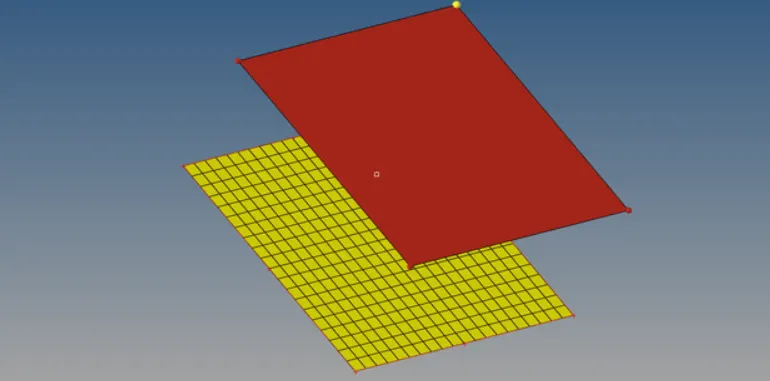
3.In assignment, one plate is meshed and another plate is meshed at 0.5units.
4.The parts mesh, it is always better to assign in the material and the property.
RBE2 and RBE3 ELEMENTS:
1.Using RBE3 elements there can be mutiple master nodes and a single slave node which means whatever load that is coming on the slave node would be distributed among all the masters nodes.
2.Another difference between them is that RBE2 provides tremendous stiffness however RBE3 element does not provide the stiffness but distributes it to the neighboring nodes. Using 1D+Rigid + an RBODY creates.
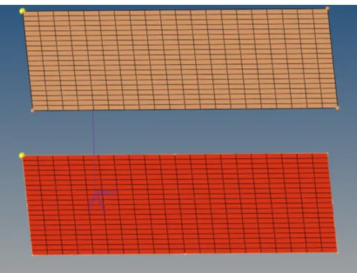
3.Meshed plates are connected with a rigid RBE3 element.
ROD or TRUSS ELEMENT:
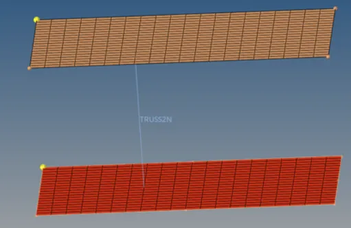
1.Bar and Rod are those straight members that can be only subjected to axial loadings like tension or compression but no bending or torsion. The cross section of the rod is always circular.
2.If any single transverse load is applied to the bar it is no more called a bar it would be called a beam. Now to deploy the rod element in the model, 1D > rods is the path.
BEAM ELEMENT:
The member which is subjected to any transverse load is called the beam. The beam can be of any shape. Using 1D > bars, the beam elements was created.
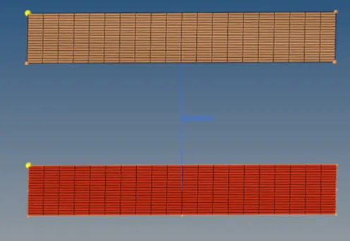
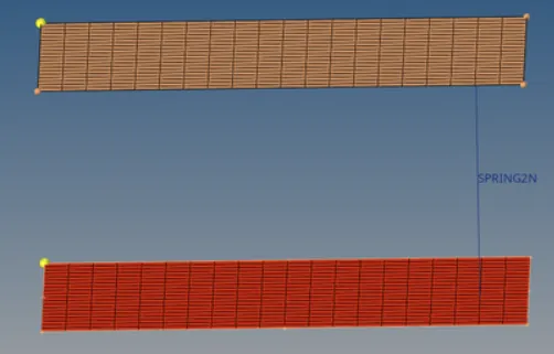
SPRING ELEMENT:
The spring can be two noded or three noded. In this model the two noded spring is created using 1D>springs.
3.MESHING OF HOUSING PARTS USING 3D TETRA ELEMENTS:
PROCEDURE:
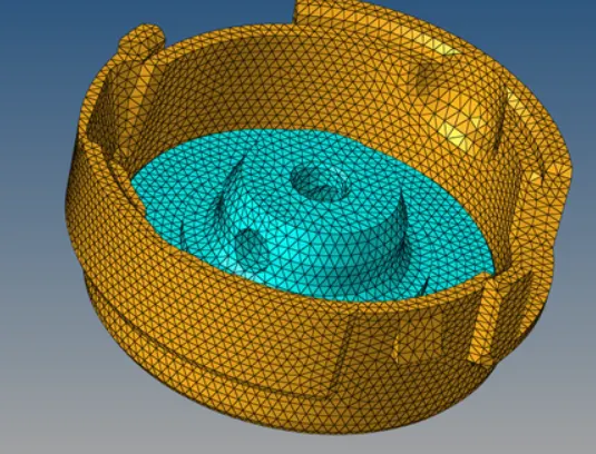
1.The .hm file of housing parts was imported in Hypermesh. There were 2 parts one was the cover and other was a hub.
2.They were not all distributed and almost no errors were present in the geometry. Both the disc and the hub were meshed by converting 2D shell elements into 3D tetra elements, using 3D > tetra mesh > Tetra mesh.
3.Performing the 2D shell mesh. Now the 2D meshing is performed using only tria elements and all the shell kept under the mentioned quality criteria. Goto 2D > automesh > element size > 5 > type > tria > mesh.
4.After the shell mesh is performed they need to be converted into solid tria elements. So select the 3D > tetra mesh option. Then select the elements under the fixed tria/quad to tetra option and then do the mesh.
5.The fixed tria to tetra option ensures the connectivity of the tria with the tetra.
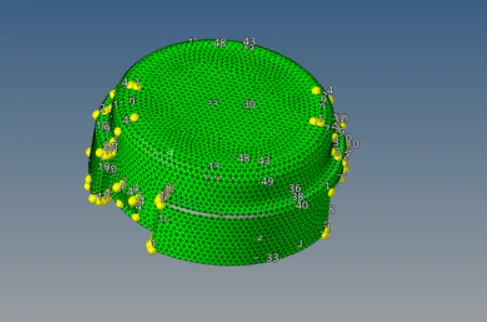
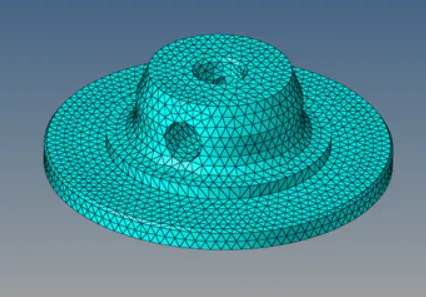
6.To create the tetra meshing with the 2D elements. For that we are going to go with 3D > Tetra mesh.
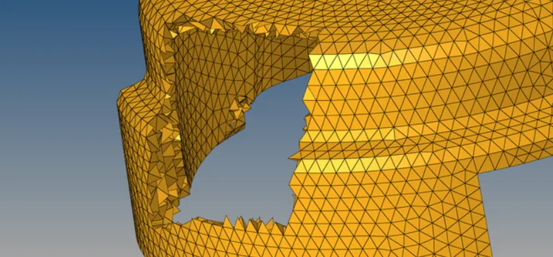
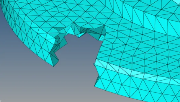
7.We want the tet collapse to be less than 0.15. So we are going to check that from the check elements. Go to 3D and going to give the value of tet collapse to be 0.15 and we going to check that how many elemnets are failing for the tet collapse.
8.To remove the tet collapse go to do the tetra mesh. So again we go to tetra mesh and going to give the tetramesh parameter and there we are going to give the ter collapse to be 0.15.
9.Remesh the components.
10.After the process we checks the tet collapse again in the mesh and check that if any elements are failing for the tet collapse.
OUTPUT:
4.MESHING OF ARM BRACKET USING BRICK ELEMENTS:
PROCEDURE:
1.The arm bracket model is imported.
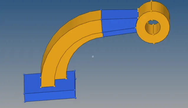
2.From the model, we can observed that the arm bracket model consists of four different sections.
3.While meshing using hexaelements manual inspection is required for modal connectivity.
4.Each section had meshed individually. Firstly the face of section 1 has meshed with 2D elements of size 10units.
5.Using 3D > Elem offset > solid layers the 2D shell is converted to 3D Hexa mesh with element thickness of 25 units and 5 layers.
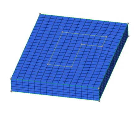
6. After meshing of section 1 for the meshing of section 2 the different methods had to follow because of its curved shape.
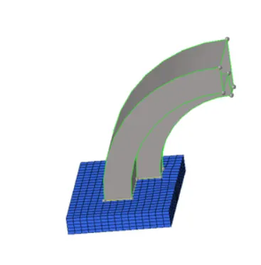
7.To mesh section 2, a centre of the curve is obtained for reference. It can be obtained using Geom > nodes > Arc center > Distance > Three nodes.
8.After that using 3D > spin > Spin elements, the shell meshed inscribed by the curve is selected and it is spin about the center for 90deg with 40 layers of elements.
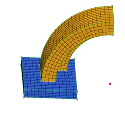
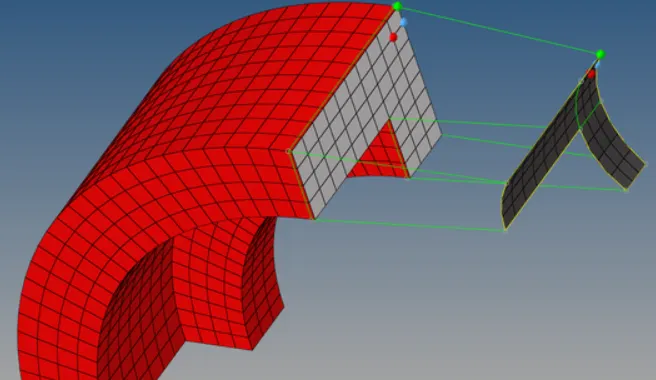
9.Once section 2 is ready with 3D hexa mesh for meshing of section 3 which is a tapered section the shell mesh of section 2 is required.
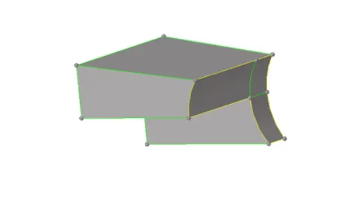
10.To get the shell mesh of section2 Tool > faces > elements are used. It appears exactly like 3D Hexa mesh of section2 it is hollow from inside.
11.The rows and columns of shell elements avaliable on one side of it the other side has to mesh with same number of rows and columns using shell elements.
12.Go to 3D > linear solid.
13.From elements and to elements can be selectted as the two end faces elements respectively.
14.Denstiy can be set 12> solids.
15.The component to mesh is boss. The option used for generating the mesh for this components is Solid Map.
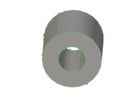
16.One side surface has meshed with 2D quad elements. The same number of nodes should be there at both ends to have the quad elements.
17.With the help of a solid map tool the destination surface the elements to be mapped nodes to which the connectivity should be there are selected.
18.For a better understanding of the solver lines along which the mesh should be generated are also selected.
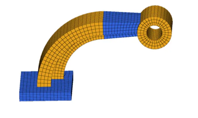
19.After generating the Hexa mesh, the next to check for the connectivity for the elements in the arm straight component and boss component.
20.Final model with the entire Hexa mesh is done.
OBSERVATION:
1.Some calculation such as speed of sound, time step, T frequency values.
2.Editing of engine file, Types of files in radioss like stater and Engine file.
3.The model connected using various 1D elements, there are several options available for the element to choose to represent any specific kind of connection. Some of those elements are learned in this work.
4.Objects whose thickness is not uniform are generally mesh with solid elements. When the developing stresses in any object are not part of the concern it is meshed using tetra elements.
RESULT:
Thus the given challenge is completed sucessfully.