Assignment 2-RADIOSS Engine File Editing & 3D Meshing Challenge
Assignment 2-RADIOSS Engine File Editing & 3D Meshing Challenge
RADIOSS Engine File Editing
Questions:
Q(1). materials properties required for calculation of speed of sound in steel as per time step calculations are Elastic modulus and density
`c = sqrt(E/rho)` where E is Elastic modulus and `rho` is density
From given FIRST_RUN_0000.rad file
E = 210000 `N/(mm^2)`
`rho` = 0.0078 `g/(mm^3)`
So, calculating speed of soung in steel `c` = `5188.745217 (mm)/(ms)`
Q(2). From FIRST_RUN_0000.rad file deployed in Hyperworks the length of the element `l` = 30.49mm
Time step formula for calculating critical time step is `Dt = l/c`
Where `l` is length and `c` is speed of sound
Form above Q(1) we got `c` = `5188.745217 (mm)/(ms)`
substituting in time step formula we get time taken for a shock wave to travel from one node to subsequent next as
`Dt = 5.876179833 ms`
So by Continuing for next subsequent nodes we get time taken for a shock wave to travel from one end of the rail to other end as
Time = 33*Dt = 193.9139345 ms
Q(3). Given length of the rail `l` = 1000mm
Time step formula for calculating critical time step is `Dt = l/c`
Where `l` is length and `c` is speed of sound
Form above Q(1) we got `c` = `5188.745217 (mm)/(ms)`
substituting in time step formula we get time taken sound to travel length of rail as
`Dt = 192.7.4822 ms`
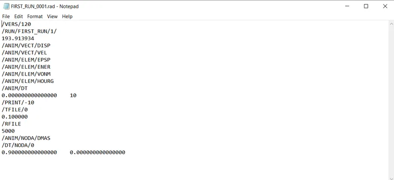
Q(4,5,6).Changed out file of FIRST_RUN_0001.rad
3D Meshing Challenge
Objective: Checking and performing the geometry cleanup for the given three models, 2D and 3D meshing of the models given using the given quality criteria.
Given Models:
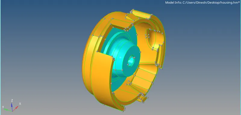
- Case 1:- Housing
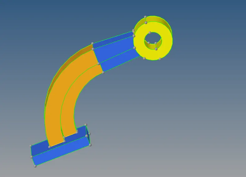
- Case 2:- Arm Bracket
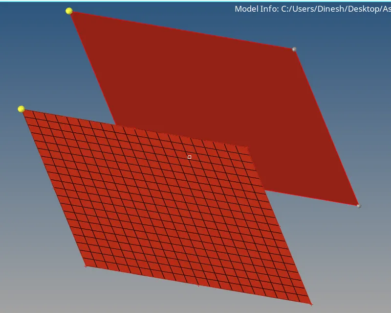
- Case 3:- 1d_elements
Given 2D Quality Criteria:
|
S.No |
Quality Criteria |
Value |
|
1 |
Target Length |
5 mm |
|
2 |
Minimum Length |
3.5 mm |
|
3 |
Maximum Length |
7 mm |
|
4 |
Aspect ratio |
5 |
|
5 |
Skew |
60 |
|
6 |
Jacobian |
0.5 |
|
7 |
warpage |
15 |
|
8 |
Min interior angle tria |
20 |
|
9 |
Max Interior angle tria |
120 |
|
10 |
Min Interior angle Quad |
40 |
|
11 |
Max Interior angle Quad |
140 |
Given 3D Quality criteria
|
S.No |
Quality Criteria |
Value |
|
1 |
Tet size |
5 mm |
|
2 |
Hexa size |
10 mm |
|
3 |
Tet collapse |
0.15 |
Case 1 Setup and Execution:
- Opening the model and geomtery clean up
Intially Opening Hyperworks and opening Part 1 from File -> Open -> Model
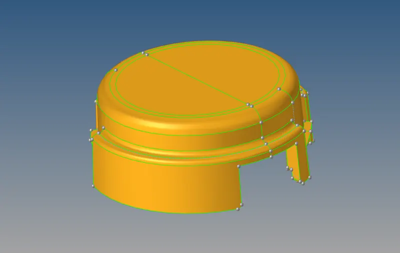
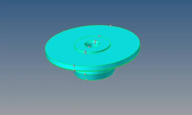
After opening it, the model will appear without differantiating boundaries and to check if there any geometry clean up to be done the, the geomtery color mode is changed from Auto to mixed.
Cover Component
Hub Component
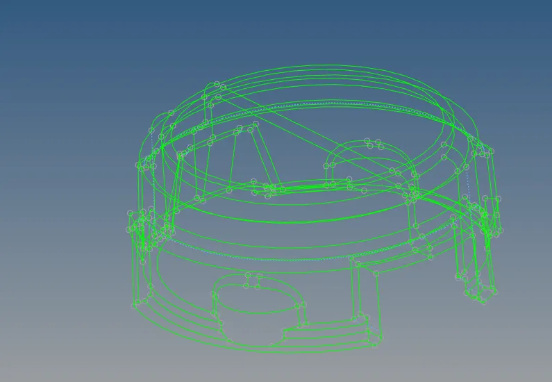
After changing geomtery color mode to mixed and switching on wire frame geomtery
Cover Component
Hub Component
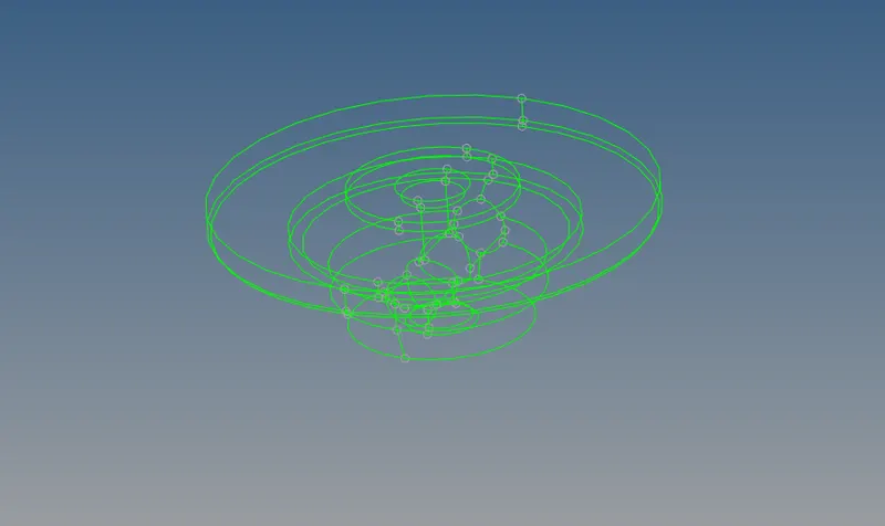
The given geometry is clean
There are different ways of meshing the above model with tetra elements.
Here we follow with 2D tria mesh and then using tria mesh to create tetra 3D mesh.
This is because this way we get minimum failures and more control over meshing and the given component is simple.
- 2D Meshing
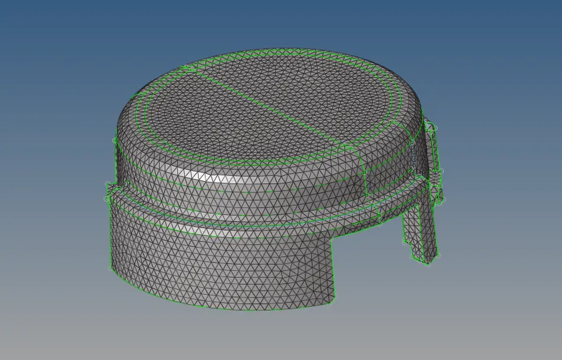
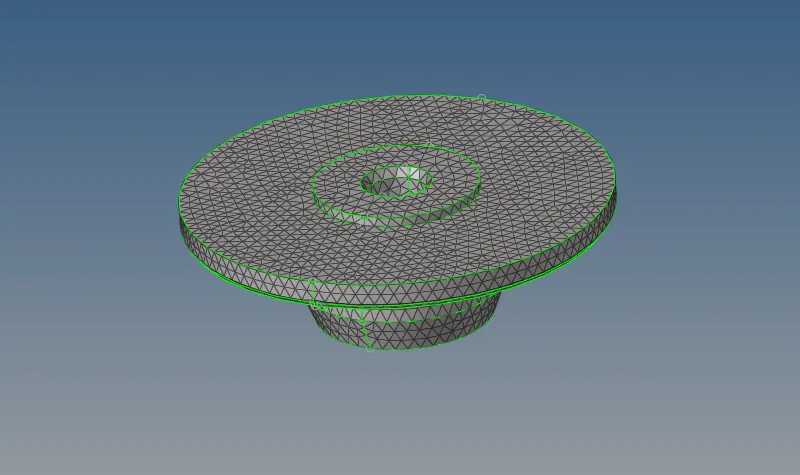
2D meshing is done using Automesh from 2D panel.
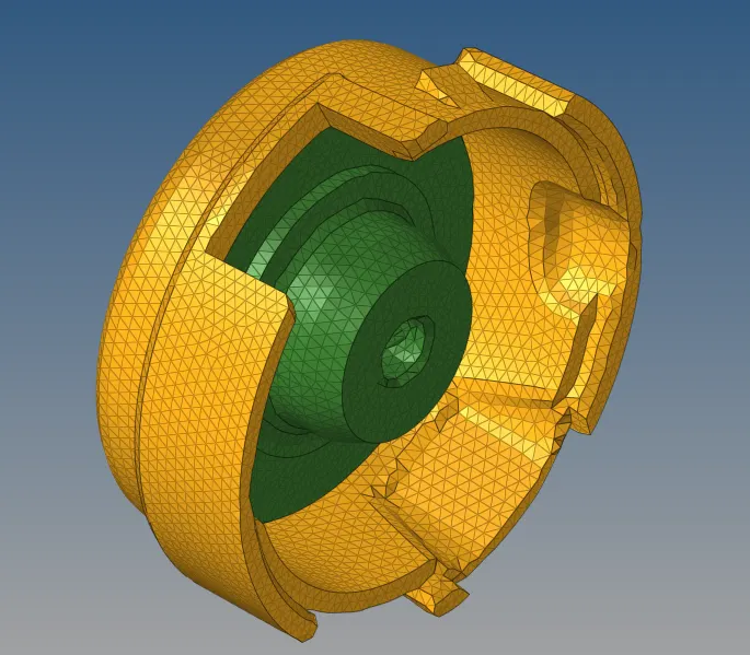
Selecting the surfaces and choosing element size to be 5 from given criteria and confirming it the surfaces are meshed.
Meshed model is shown below.
Cover Component
Hub Component
3D Meshing:
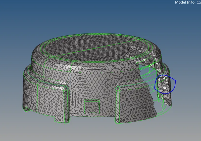
From the 2D mesh the formation of 3D mesh can be done using 3D panel -> tetramesh -> Tetramesh -> Fixed trias/Quads to tetramesh (this makes the mesh with connectivity with 2D tria elements) -> Selecting the component and keeping the simple pyramid and mesh to current component as it is and confirming it meshing is done.
Cover model
Hub Model
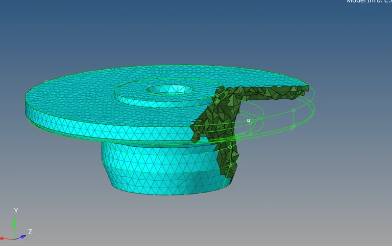
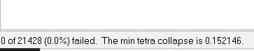
Then the tet collapse is checked using tool -> check elements -> 3D -> Tet collapse
Case 2 Arm Bracket Setup and Execution:
- Opening the model and geomtery clean up
Intially Opening Hyperworks and opening Part 1 from File -> Open -> Model
After opening it, the model will appear without differantiating boundaries and to check if there any geometry clean up to be done the, the geomtery color mode is changed from Auto to mixed.
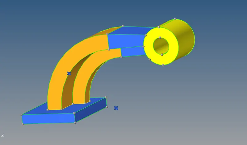
After changing geomtery color mode to mixed and switching on wire frame geomtery
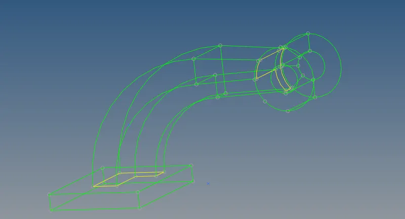
Here the yellow lines represent contact between components which is fine.
The model has no geometrical errors and so geomtery is clean.
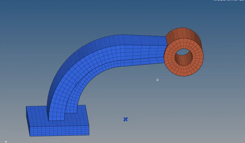
This model we follow 3D Hexa mesh and we follow with different meshods for different components.
- Meshing
First we go with the
base component
where meshing is done using Automesh from 2D panel.
Selecting the top surfaces and choosing element size to be 10 and quads only and confirming it the surfaces are meshed.
Meshed model of base component is shown below.
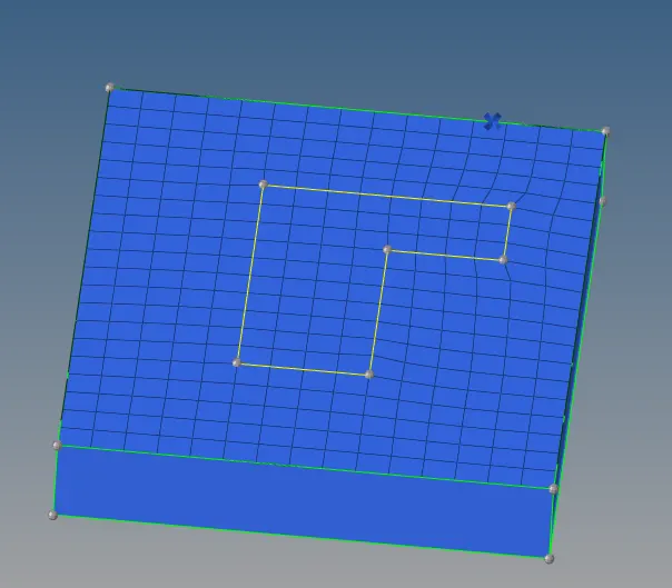
After meshing of top surface is done the 2D mesh is then extruded to 3D elements using
3D -> element offset -> solid layers -> in 2d elements to offset, Selecting the top surface 2D elements -> in Along geomtry to follow, selecting the side surfaces -> giving the number of layers to be 5 and total thickness we got after measuring to be 25 and confirming it by offset + 3D hexa meshing is generated. we can check by masking (from tools) some of 3D elements.
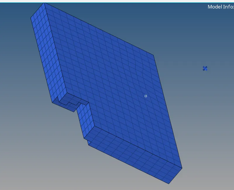
After meshing of base component is done, we go for
arm_curve,
since this is curved component the 3D elements are generated using 3D -> spin
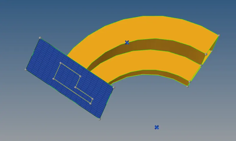
In spin -> spin elems -> selecting only the inner boundary 2D elements -> then selecting the profile with N1, N2 and N3 and the center of the arc B with the point s on the 2D boundary of the curve , center of the curve feature line, end of the curve feature line and the the arc center (we got from selecting the 3 points from geometry -> distance) and by giving the the angle as 90, giving the elements on off spin as 25 and confirming it by spin+ the hexa elements of the arm are generated.
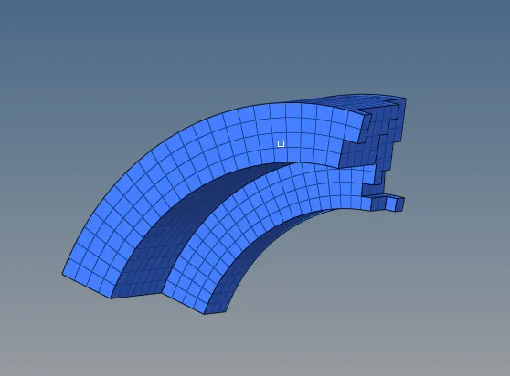
After meshing of arm_curve then we go for
arm_straight
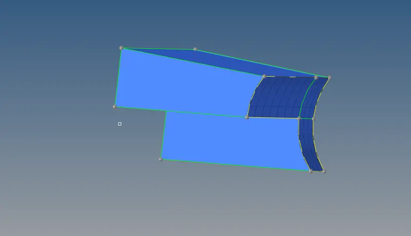
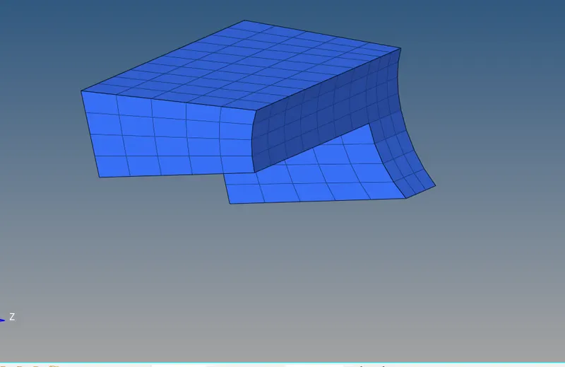
we need elements on both ends, one end of the 2D elements are generated by tool -> faces selecting the arm_curve component and confirming it with find faces we get 2D faces on one end and matching the number of nodes the other end is meshed as well with quads using 2D -> automesh -> selecting surfaces and confirming itmeshing is done.
Using these 2D meshed elements 3D mesh is generated using 3D -> linear solid -> from elems -> selecting one end elems and selecting the N1, N2, N3 on one corner of the elements in one orientation -> to elems -> selecting other end elems and selecting the N1, N2, N3 on same corner in the same directions, density as 5 and confirming it the 3D hexa elements are generated.
Next we go for
Boss component,
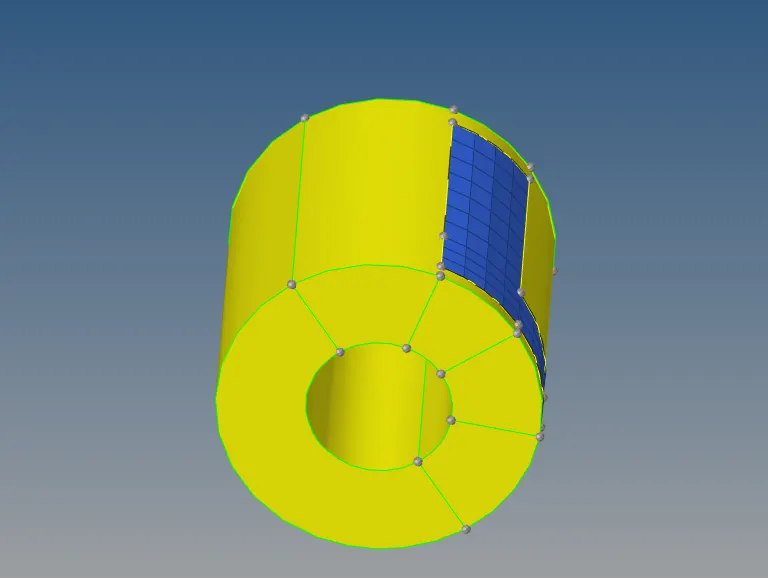
Using these arm_straight the points are then generated on the boss surface lines on both ends.
the 2D meshing is done on one end of surface where multiple splitting is done using 2D -> automesh and adjusting the number of nodes on both ends the mesh is generated.
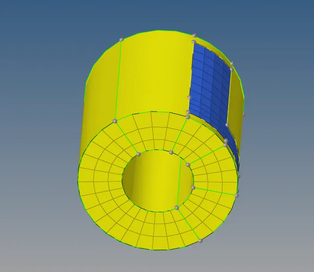
These 2D elements are mapped with 3D element to the other end using
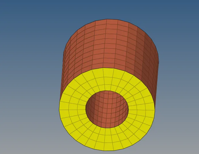
3D -> solid map -> general -> source geom as none -> destination geometry as the single opposite surface -> selecting along geom as the sides outer and inner surfaces and along parameters as 10 the 3D mesh is generated
Case 3 1d_elements Setup and Execution:
- Opening the model and geomtery clean up
Intially Opening Hyperworks and opening Part 1 from File -> Open -> Model
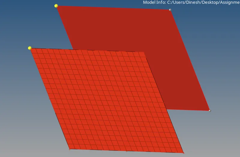
- 2D Meshing
2D meshing is done using Automesh from 2D panel.
Selecting the surface and choosing element size to be 5 and confirming it the surfaces are meshed.
After meshing is done, The quality of the mesh is checked from quality index option for given quality criteria.
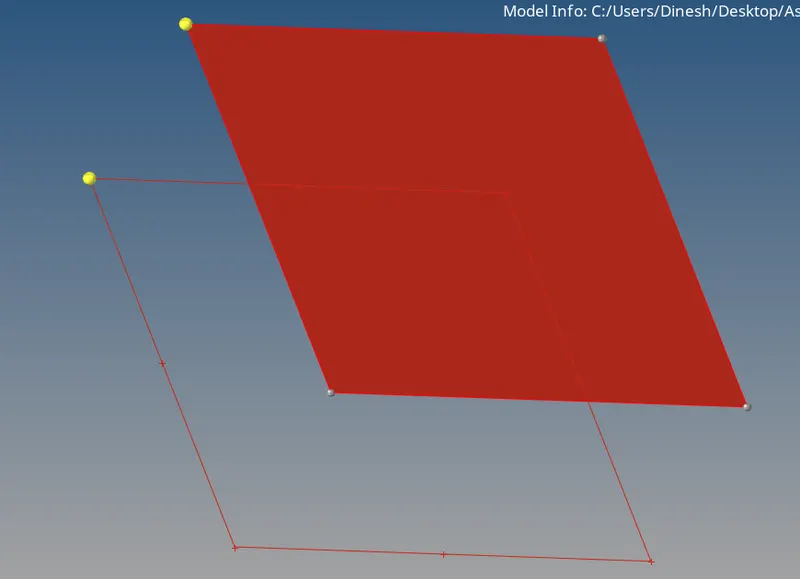
After meshing is done
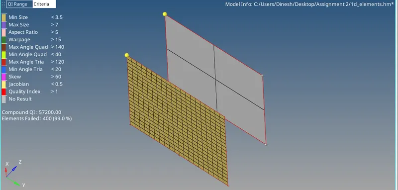
The elements which are failing are rectified one by one using various options
Rebuild mesh, element optimize from quality index cleaup tools.
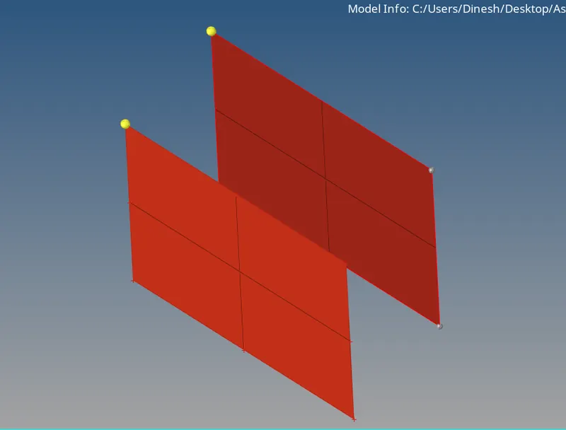
Results:
Housing:
arm Bracket:
1D elements:
Conclusion:
Checking and performing the geometry cleanup for the given three models, extracting the mid surfaces, 2D meshing of the extracted mid surfaces using the given quality criteria and assigning the thickness to the created mesh is done using Hypermesh 21.0.