Assignment 2-RADIOSS Engine File Editing & 3D Meshing Challenge
ASSIGNMENT-2 RADIOSS ENGINE FILE EDITING AND 3D MESHING
CALCULATION:
Check the material properties of the rail component and calculate the speed of sound in steel rail = 5188.74mm/ms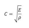
E = 210000
Density = 0.0078
C =5188.74mm/ms
The length of the rail is about 1000mm. Calculate the time takes for a shock wave to travel from one end of the rail to the other.
Time for sound to travel the length of the rail= 0.192ms
length=L=1000
Speed of the sound = C= 5188.74mm/ms
DT= L/C
= 1000/5188.74 = 0.192ms
The length of the rail is about 1000mm. calculate the time takes for a shock wave to travel from one end of the rail to the other.
MODEL 1:
- Import the engine file
- go to view - browser - hypermesg - solver - run - engine run and change the time stop 60.
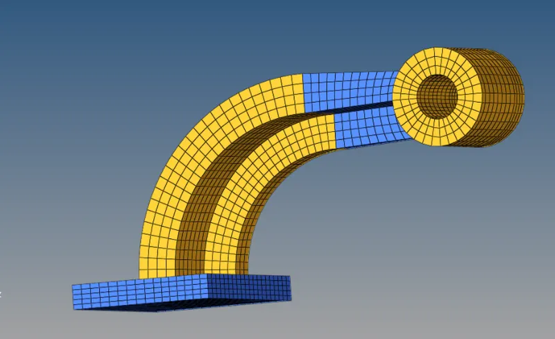
- set the frequency of animaion output at a given 20 animation step.
- Tfreq= 60/20
- change in Tfreq=40
- go to engine keyboard-Animation-animation/DT-Eng Animation/DT
- Set Tfreq 40
- change/print-10
- 3D meshing hex mesh 10
- taken the base part, hide the remaining parts and mesh the component
- go to 2D mesh, select automesh where element size is 10.
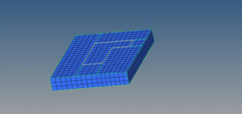
- Go to the component select the arm curve, make it as current component.
- press F4-3 nodes- select the curve- create a node at center of curve
- In order to mesh the curve go to 3D Page - spin select the element - center node - dreg line - select angle , keep element size 10..
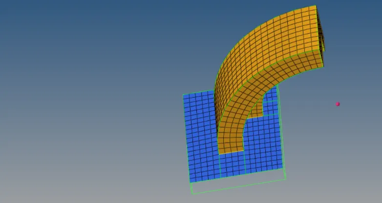
- go to tool page - face - select the arm curve component - assign tolerance value - find face.
- In order to mesh arm straight , mesh the front face of it with same no of element placed in arm curve .
- go to 3D pages- solid map- source element- destination element - same 3 nodes for the faces of direction N1,N2,N3.
- Like previous step we have generate face for arm structure in next steps.
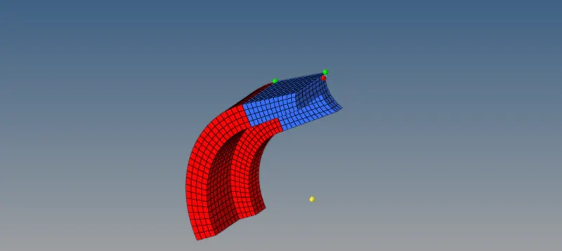
- In order to mesh the boss we have create some nodes in boss component.
- go to 3D page -solid map-deselect source geom-dest geom-select mixed in along geom-element drag, make sure that element size 10
- go to shift+f11 - select the solid map component - move to boss component.
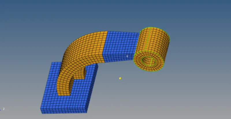
- And save the model in HM format.
MODEL 2:
AIM:
- To create 1D elements and assign properties to them.
PROCEDURE:
- First import the model in hyperworks and after importing the model ,mesh the surface .
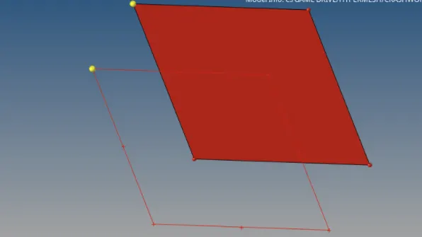
- now create 1D element between the 2 meshed surfaces to perform this operation go to the main menu and select 1D.
- In 1D element first select rods and element type TRUSS 2N. select 2 opposite nodes anywhere on the shel element and this will create a 1D element between them.
- Similarly create one or more element i.e, a bar / beam element . this time 1D ,select bars and element type as BEAM3N.
- Now create properties for these element by going to the tool bar.
- For TRUSS2N element select card image as P2_TRUSS and hyperbeam selection select section type as HMCIRCLE and give any suitable thickness to it.
- similarly for BEAM 3N element select card image as P3_BEAM and in hyperbeam section select selection type as HMBOX and give any suitable thickness to it
- once all the properties are created assign them to their respective components.
- After all the components are assigned with their respective properties , go to tool bar > select from list > 1D detailed element represtation .
- save the model in HM format.
RESULT:
- 1D element were successfully created and the properties have also been assigned to the respective components.
MODEL-3
- 3D meshing tetra mesh
- open the next component , to check view 3D topology go to 2D page-auto mesh-select surface-element size as 5- mesh types as trias -click mesh.
- next move to 3D page-tetra mesh - select the component- move tetra parameter - select the min tetra size 5- again move to tetra mesh- mesh the selected component.
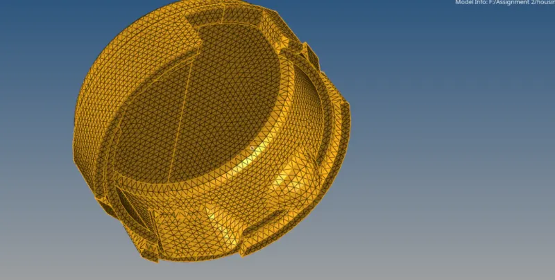
- go to F5 mask option -after tetra mesh we have check wheather it done properly, after unmask the element .
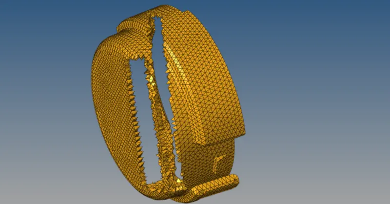
- check the quality of the element press F10,3D-to check tet collapse- these component is meshed with zero error.
- same procedure hub component
- go to 2D pages-auto mesh - select surface-element size as 5- mesh type as trias -click mesh.
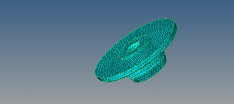
- next move to 3D page-tetra mesh - select the component- move tetra parameter-select the min tetra size 5-again move to tetra mesh- mesh the selected component.
- check the quality of element press F10,3D - to check tet collapse-27 element are failed- saved the failed element.
- move mask-element-reterive - mask- reverse failed element are visible.
- go to shift+F2- nodes- displaced -odd nodes, it will help to identified the failed element.
- select the element and remesh it.
- go to mask-unmask the element, the component is meshed completed with zero element failure.
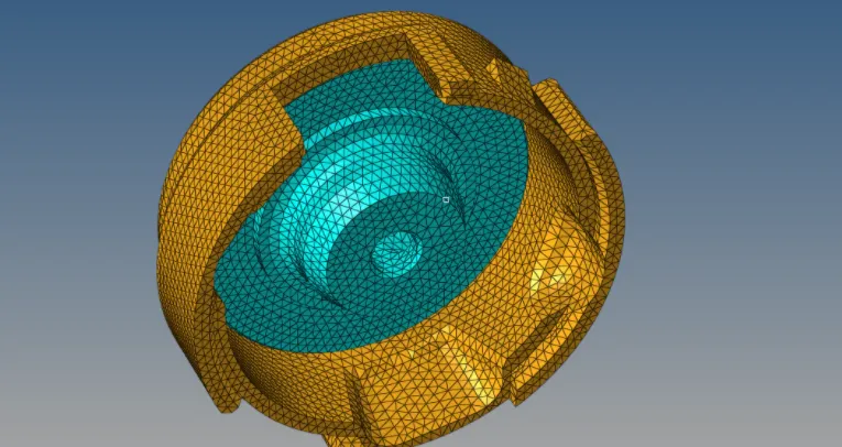
- here the finall part of housing is done.