Assignment 2-RADIOSS Engine File Editing & 3D Meshing Challenge
* Answers for above mentioned questions :
1. Check the material properties of the rail component and calculate the speed of sound in steel rail=___3.67m/s____
I.e,
* Given formula to calculate are mentioned below :
Elemental time step
* delta Tc = l/c Given : Mild Steeel AISI 1018
Rho = 7.8e-6 kg/mm3 E = 205gpa
delta Tc = target / critical timestep:
0.5 micro seconds(5e-7 Seconds)
where C = Sqrt(E/rho)
l = length of element
* Substitution of C
C = sqrt(205/7.8e-6)
C = 3.67m/s
2. The length of the rail is about 1000 mm.calculate the time takes for a shock wave to travel from one end of the rail to the other.
Given creitical timestep:
delta Tc =0.5 micro seconds( 5e-7 seconds ) so
The time takes for a shock wave to travel from one end of the rail to the other is 0.5 micro seconds .
3.Time for sound to travel length of rail=___1000mm___
Aim : To perform tetra for the given Geometry.
Objective : To Perform Tetra mesh with target element as 5 for given housing compound and to perform the mesh for given parameters.
*Opening the geometry using radiosis are shown below:
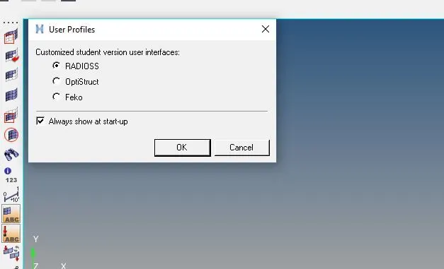
* Click to hypermesh and select radioss ,click ok as shown below
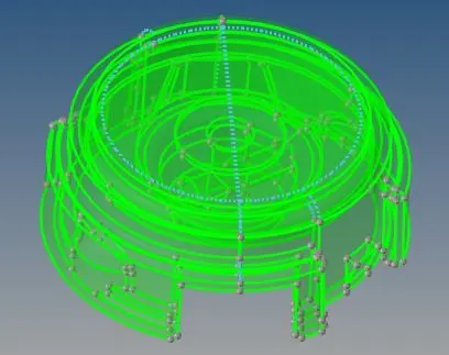
* The given housing model for tetra mesh are shown below:
* 2d meshing the model:
* select the geometry one by one
* Hiding the geometry and performing the mesh one by one
* Select 2d from sub panel and click to automesh
* In automesh apply the target element as 5 and select the mesh type as tria ,finally click mesh as shown below


* one part of geometry after meshing :
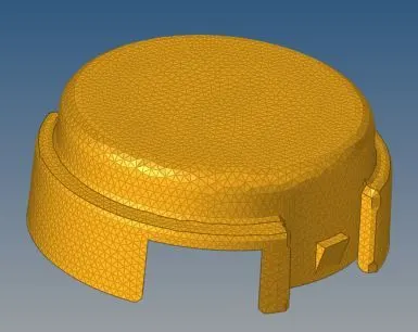
* anonther part of geometry after meshing :
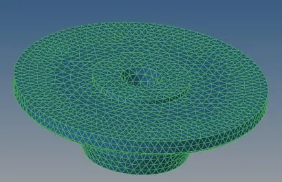
Creation od 3d tetra mesh :
* After meshing the given model ,select 3d and click tetramesh
* select the required compound which need to be tetrameshed and click mesh as shown beolw


* The model after tetramesh are shown below :
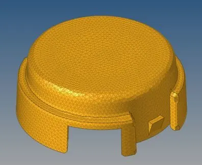
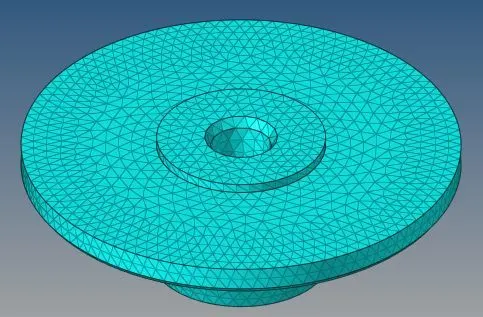
* Checking the tetra elements for tet collapse :
* click to Tools from panel and then to check elements
* In check elements,apply the tet collapse as 0.15 and click in tet collapse ,if any errors it showns or else ignore as shown below
* As mentioned above there are no tet collapse error further moving to next process


* Conclusion : The given model can be done the process of tetrameshing with given parameters .the file are attached below.
For Model 2
Aim : To perform hex mesh for the given Geometry.
Objective : To Perform hexa mesh with size as 10 and acheive the mesh parameters,further to check the tet collapse given .15 of given bracket arm model.
*Opening the geometry using radioss are shown below:
* Click to hypermesh and select radioss ,click ok as shown below
* Given model :
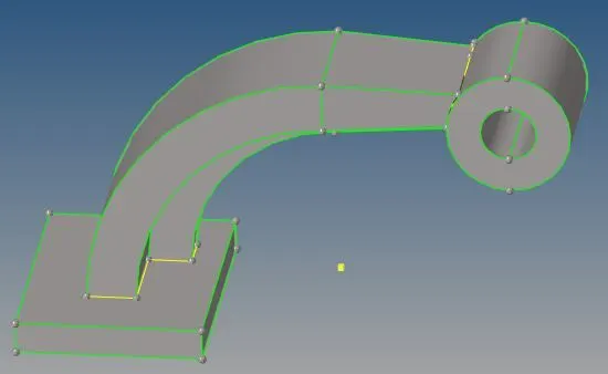
* In above shown fig the yellow edge that contains thriple edges which needed for hexa mesh .
* Meshing the geometry :
* selecting 2d From sub panel and click automesh as shown below
*In automesh giving the target element as 10 and keeping the mesh type as mixed
* And selecting the required surface which need to meshed are shown below :
* The surface Before mesh are shown below :
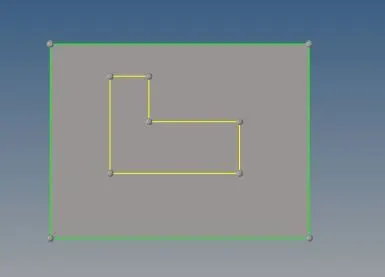
* The surface after mesh are shown below :
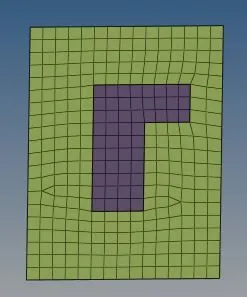
* Performing of hexa mesh :
* Performing the model one by one
* Element offset :
* Select 3d from sub panel and click element offest from panel.
* In element offset select the element which need to dragged and select the surface for dragging
* Calculate the distance between those surface ,the calculated distance in given geometry is 25mm
* The distance are calculated inorder to insert the number of layers as 5
* select the elements and the surface ,click offsett+ as shown below
* Model after element offsett:
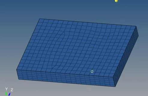
* For next model Performing spin drag option:
* Model :
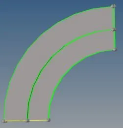
* In above shown fig need to be done a hexa mesh .
* Hiding the geometry and performing the mesh one by one
* Creating the center using Distance option :
* In model create a center using distance from panel ,keeping in geometry option as shown below
* Model before center Point :
* Model After center point :
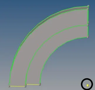
* Select geometry from panel and click distance
* Clicking to three points ,holding rightclick select three points and click points between as shown below
* Model after performing distance option:
* The encircled region shows the center point created .
* model before hexa mesh:
* Meshing
* Selecting a surface as base ,can be performed as spin drag elements options
* select the base surface and mesh those surface as shown below
* Select the surface of model 1 and mesh with target element 10
* Surface which need to be meshed are shown :
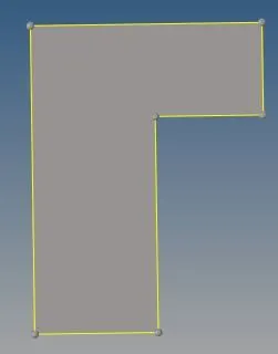
* Surface after mesh :
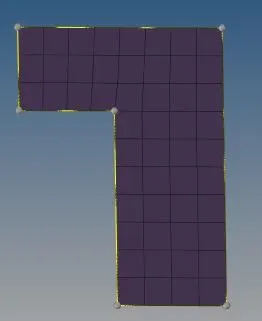
* Performing of hexa mesh :
* Using above meshed surface spin drag can be performed.
* Select 3d from panel and click spin
*After selecting spin click spin elements and select the elements which need tto be dragged .
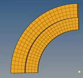
* Applying the angle as 90 and giving on spin as 50 because calculated distance is 100 and finally click spin +


* The model after performing spin are shown below:
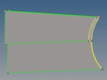
* For Model 4 :
* Performing Linear drag :
* Selecting a surface as base ,can be performed as Linear drag elements options
* select the base surface and mesh those surface as shown below
* Select the surface of model 1 and mesh with target element 10
* Surface which need to be meshed are shown :
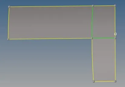
* Surface after mesh :
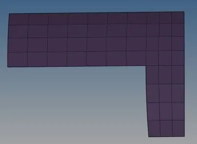
* Performing of hexa mesh :
* Using above meshed surface Linear drag can be performed.
* Select 3d from panel and click Linear drag
* Keeping in drag elements ,Select the elements which need to be draged and also select the lines to drag along the elements
* Finally click drag


* The model after performing Linear drag are shown below:
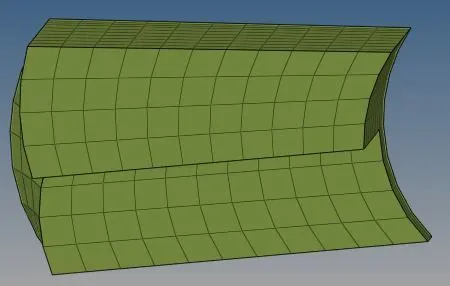
* For Model 5:
Model 5:
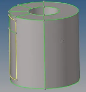
* Meshing
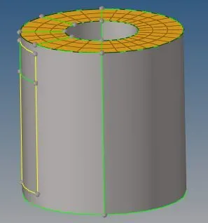
* Select the top surface for meshing
* Click 2d and select automesh apply the target element as 10 ,given above finally click mesh as shown below
* Surface which need to be meshed are shown :
* Surface after mesh :
* Performing solid map :
* Select 3d and click solidmap from hexamesh
* In solid map ,Keeping in general select the meshed elements which need to be dragged and the destination surafce
* And also select the lines which is along the elements ,given element size as 10 .furthermore click mesh as shown below


* Geometry before solidmap:
* Geometry After solidmap:
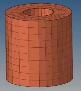
* The complete model after performing the hexamesh option :
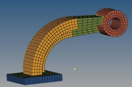
* conclusion : As we observerd the arm bracket model which is spiltted into parts and we can perform the hexa mesh with any target element and acheive the tetcollapse in given mesh creteria .
* Editing of engine file :
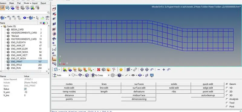
Given engine file :
* Importing the radioss file:
* Open the user profile using radioss
* From browser click import solver and change the profile to radioss as shown below
* In Import solver deck change the file type as radioss and select the radioss file ,click import .as shown below

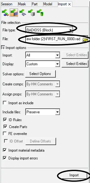
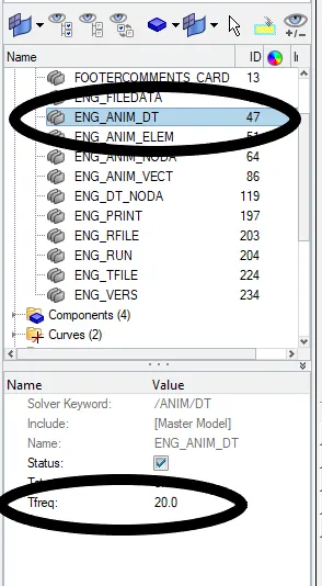
* Next need to edit the time frequency from card in radioss to 20 as mention above
* In model browser click the card name ENG _ANIM_DT and select tf ,edit the value
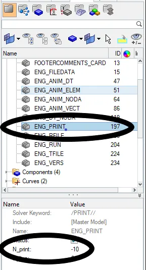
* Furthermore to ENG PRINT edit the vakue to -10 as mentioned above as shown below
* Exporting the file :
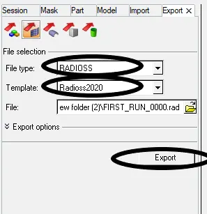
* From browser click export option
* Change the file type as radioss and click export as shown below

* Conclusion :The engine file can edit the engine time frquency value and engine print value.