Assignment 11
single cyl DI add case 2 with discretization length 0.1 mm for intake runner and compare with default case 1
Simulation time case 2 take more time average than case 1 because of dicretization length. If we decrease decrase discretization length it will take more simulation time to calculate wave dynamics in intake runner so we need to choose correct dicretization length because it will affect simulation time and speed
ENGINE GEOMENTRY
In this table we can see variation in brake power between case 1 and 2 and this is same for torque bsfc and in cylinder preasure so if we decrease dicretization length we can capture wave dynamics accuratley but it will take more simulation time and more time step to calculate. but there is no so much deviation it has small deviation
case 1 case 2
Brake power KW 33.5 33.4
TORQUE [NM] 88.9 88.7
BSFC [g/KWh] 257.7 258.5
IN CYL PRESSURE BAR 110.99 109.0
2. Explore tutorial no 2 (GEM3D) - “Building intake manifold from STL model
Go to file gti in example - acoustics - nonlinear standard- select stl file cad model to space claim and make it flow component we need only flow component and we need to convert 3D cad model of intake system into one dimensional
and open gem 3D from spaceclaim and another method we can open from gem 3D copy the folder path of gem all paste in open file in gem 3D plenum 3D model is imported in to gem3d
STEP 1 OPENNING CAD MODEL IN GT SPACECLAIM
STEP2 OPENNING 3Dmodel in gem 3D
STEP 3
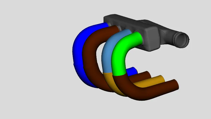
IN THIS STEP GO TO CONVERT COMMAND CLICK SEPERATE BY CURVES. AND USING 3 POINT CUTTING PLANE CUT PLENUM AND RUNNER SEPERATLEY AND RIGHT CLICK IN COMPONENT GO TO CONVERT SHAPE IN TO COMPONENT AND SELECT PIPE AND CHHOSE MULTIPLE BENDS AND CHOOSE CUSTOM PLANE CHECK AVERAGE DIAMETR AND PUT THE AVERAGE DIAMETER IN THAT DIALOG BOX NEXT CHOOSE FROM PORT 1 IT SELECT DIAMETER FROM PORT ONE OTHERWISE THE PROFILE SHAPE IS DIFFERENT WE NEED TO CHHOSE DIAMETR PROPERLY
Here choose the intial state pressure temperature fluid mixture
step 4
here chhose orife connection for smooth change of diameter and select forward discharge coefficient has 0.95 and select SA connection chooce inlet and outlet comnnection by right click the component click add connection choose the connection between the component orifice
step 5
in this step again use normal pipe cutting cut pipe and convert shape to component choose straight pipe , diameter of pipe choose port no correct amd use 3point cutting plane cut and choose shape to component select flow split and do same procedure and hide remaining component keep plenum and cut using 3 point cutting plane and choose convert shaape to component and select flow split
STEP6
Finaly choose flow option from tool bar GT used to know there is connection between these two flow components so that choose floww connection from tool bar and extrude connection from tool bar make connection between these pipe flow components and use export to gt model from tool bar discretization tab will be open
choose discretization value and choose placement method for parts not in placement file as graphical orientation and click discretize ant it will convert to one dimensional model
we can connect to our engine model through intake port and valve template