Assignment 1-2D Meshing Challenge
PRACTICE MODELS MESHING
OBJECTIVES :
To
- Clean the geometry.
- Extract midsurface.
- Clean midsurface geometry.
- Ignore holes less than dia 5mm.
- Create 2D mesh with target length 5mm, min 3.5mm max 7mm.
- And assign proper thickness, by creating a generic property for 3 components.
PROCEDURE :
1. PART-1 COMPONENT
A. GEOMETRY CLEAN UP
1. Import the part-1.hm file to Hypermesh .
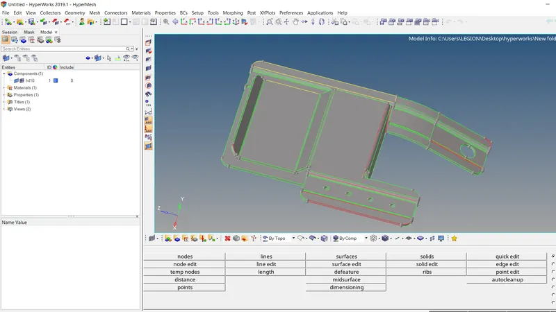
2. The component has more free edges and duplicate faces. Using Quick edits > delete surf delete duplicate surfaces. Toggle edges is ued to stitch the free edges by increasing tolerance values. Quick edits > Filler surface is used to fill the deleted surface.
3. Surface edits > trim is used to trim surfaces and later can be toggled.
4. Using wireframe mode we can check the geometry for free edges.
B. MIDSURFACING
1. GEOMETRY > MIDSURFACE using offset + planes + sweep , the surfaces are selected and midsurface is created.
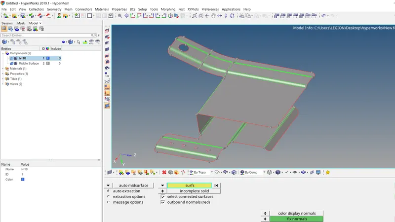
2. Fill the holes less than 5mm diameter using Quick edits > filler surf and suppress the lines using toggle edges.
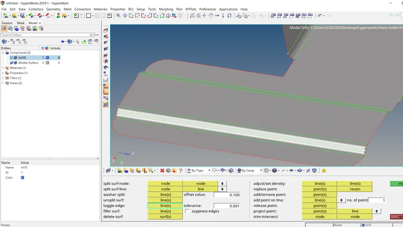
3. Toggle the unwanted feature lines that could fail for min length.
4. Assign the property and material in the optistruct user interference.
C. MESHING
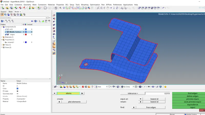
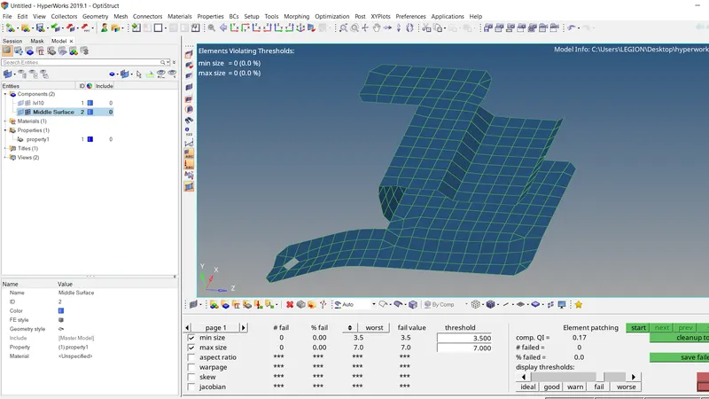
1. Set the mesh parameters and quality criteria , min lenth = 3.5mm , max length = 7mm.
2. 2D > Automesh the component with target element size 5mm.
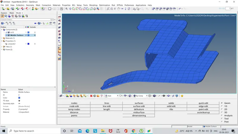
3. Under 2D > Quality index, cleanup the elements that fail. Driag tria elements, place nodes, element optimize are effectively used to clear quality element fails and check for the feee edges.
2. PART-2 CLIP REPAIR
A. GEOMETRY CLEANUP
1. Import the part-2.hm file to Hypermesh.
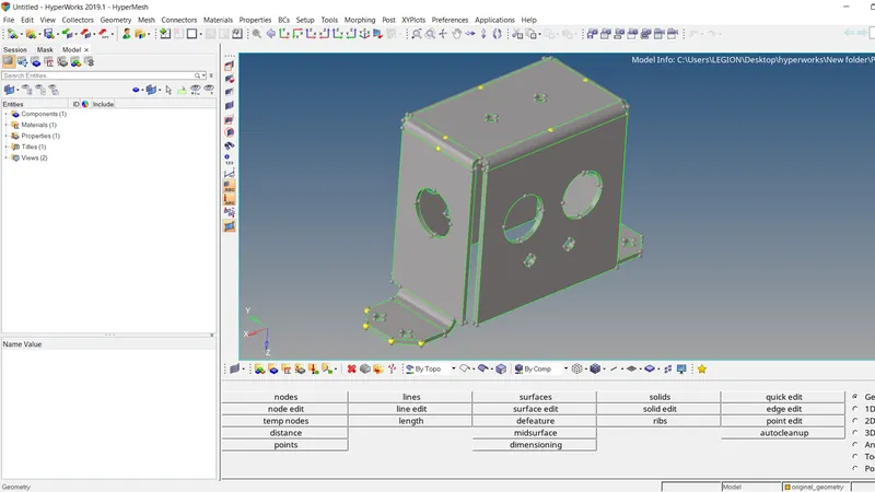
2. The component has more free edges and duplicate faces. Using Quick edits > delete surf delete duplicate surfaces. Toggle edges is ued to stitch the free edges by increasing tolerance values. Quick edits > Filler surface is used to fill the deleted surface.
3. Surface edits > trim is used to trim surfaces and later can be toggled. Shift+F2 is used to clear all nodes.
4. Using wireframe mode we can check the geometry for free edges.
B. MIDSURFACING
1. GEOMETRY > MIDSURFACE using final edit tool , the two surfaces are selected and have to click middle mouse button for midsurface and continue to repeat the process.
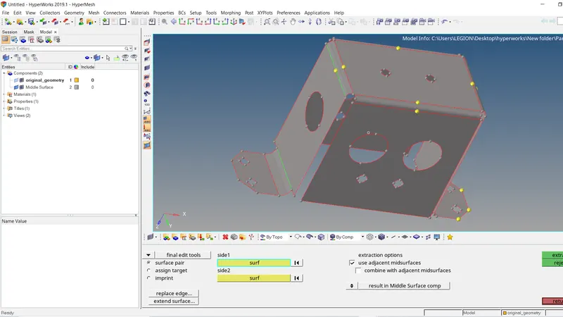
2. Quick edits > Filler surface is used to fill the holes and then use toggle edit command to suppress the lines. Washer zone is created for holes.
3. Assign material and property.
C. MESHING
1. Set the mesh parameters and quality criteria , min length = 3.5mm , max length = 7mm.
2. 2D > Automesh the component with target element size 5mm.
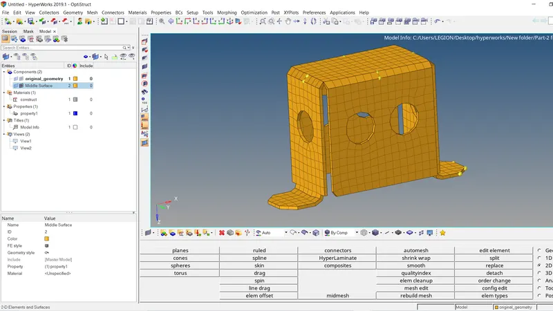
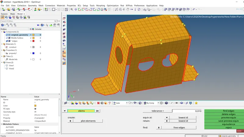
3. Under 2D > Quality index, cleanup the elements that fail. Driag tria elements, place nodes, element optimize are effectively used to clear quality element fails and also free edges.
3. PART-3 MOUNTING BRACKET
A. GEOMETRY CLEANUP
1. Import the part-3.hm file to Hypermesh under radioss profile.
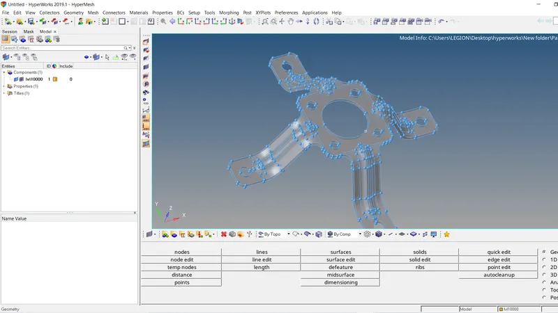
2. The component has more free edges and duplicate faces. Using Quick edits > delete surf delete duplicate surfaces. Toggle edges is ued to stitch the free edges by increasing tolerance values. Quick edits > Filler surface is used to fill the deleted surface.
3. Surface edits > trim is used to trim surfaces and later can be toggled. Shift+F2 is used to clear all nodes.
4. Using wireframe mode we can check the geometry for free edges.
B. MIDSURFACING
1. GEOMETRY > MIDSURFACE using offset + planes + sweep , the surfaces are selected and midsurface is created.
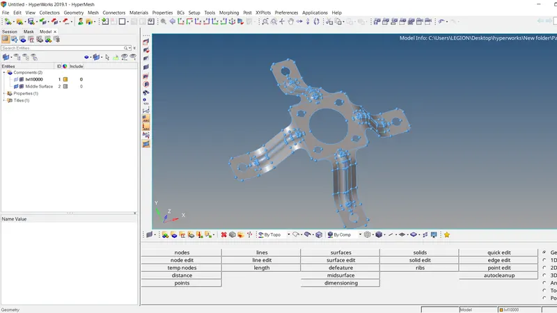
2. Quick edits > Filler surface is used to fill the holes less than 5mm and then use toggle edit command to suppress the lines.
3. Assign material and property.
C. MESHING
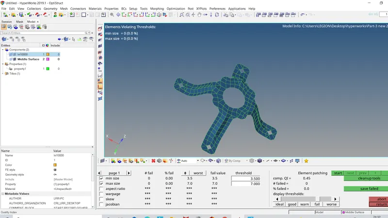
1. Set the mesh parameters and quality criteria , min length = 3.5mm , max length = 7mm.
2. 2D > Automesh the component with target element size 5mm.
3. Component is then reflected using Tools > reflect and nodes and connected using replace nodes(F3).
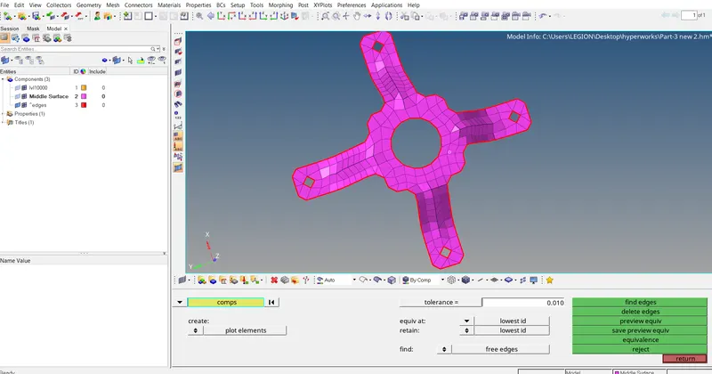
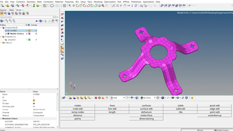
4. Element quality is checked for failiures using 2D > Quality Index and thickness is previewed using 2D detailed representation.
CONCLUSION :
1. The geometries are cleaned up by removing free edges.
2. The midsurface is extracted and cleaned up again for proper meshflow.
3. The holes below 5mm are closed.
4. 2D mesh is generated within quality criteria.
5. Thickness for property and material is assigned.