Assignment 1-2D Meshing Challenge
The goal is to clean up the geometry. Take out the midsurface. neat midsurface geometry. Leave holes less than 5 mm alone.
Make a 2D mesh with a target length of 5 mm, minimum 3.5 mm, and maximum 7 mm. then designate the appropriate thickness by producing a generic.
Procedure: Part 1: Exercise
1. Open Hypermesh and import the file by selecting Import > Import Model.
2. Click the files, choose the model, and then select Import.
3. Choose Topo as the geometry color mode.
4. Use the Quick Edit Command Tool to eliminate the yellow and red lines.
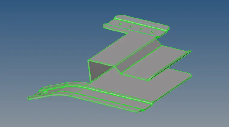
5. Examine the model in which it fails, as part 1 of the accompanying figure illustrates.
6. The yellow lines request to be converted to green lines, indicating the existence of another surface. This surface should be deleted in order for the yellow lines to become green.
7. To clear the remaining cleanups in the specified model, repeat the previous steps.
8. Use the rapid edit tool in the geometry to thoroughly clean the geometry.
9. The additional surface will be eliminated by using delete.
10. A few red lines in the geometry may be cleared by selecting Quick Edit and toggling the lines by adjusting the tolerance.
11. Finished the previously indicated geometry clean up.
12. Next, select the mid surface option from the 2D section tool bar after finishing the geometry clean up.
15. After that, as indicated below, automatically construct a new component by extracting the midsurface.
16. The parent geometry surface displays the mid surface on the graphical area; let's conceal it.
17.Determine the minimum and maximum sizes for the criterion file, as well as the desired element size, which should be 5.
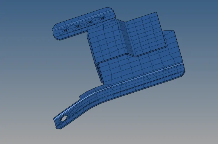
18. Next, using 2D→Automesh to mesh the whole component.
19.Mesh every surface displayed below using the procedures mentioned above.
20. Assign thickness when creating a new property and meshing it in.
21. Assign thickness when creating a new property and meshing it in.
24. Let's conceal the parent geometry surface such that the graphical area's mid surface is visible.
25. I am separating into symmetric position and taking offside will mesh and reflect the mesh in less time by utilizing Quick Edit.
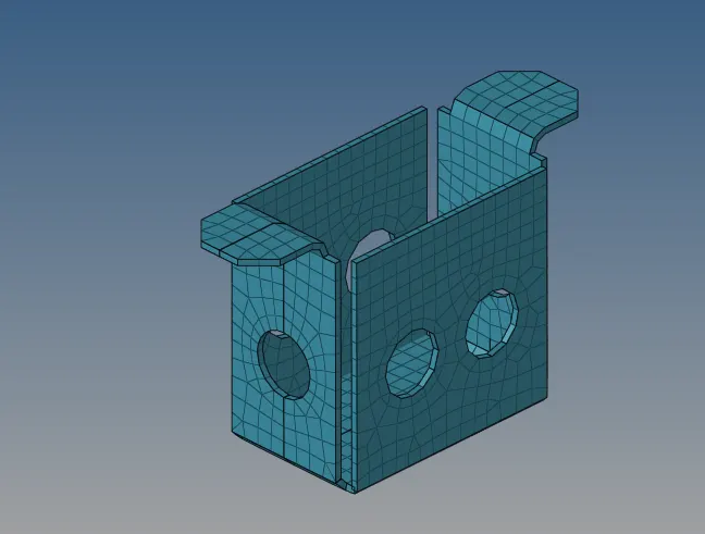
26. The component that we previously discussed in the section above is now meshing.
27.Next, select Tools → Reflect from the main menu bar.
28. Verify the necessary connection once the elements have been reflected.
29. Choose Tools → Edges.
30. Elements are automatically joined when the edge tool is used.
31.Next assign the thickness to discuss the above as it is doing thickness.
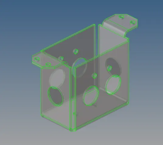
32. Since there is no geometry failure, I will go right to the mid surface as previously said.
33. Next, using automesh mesh to create the component in 2D.
34. Choose→2D→Automesh→Surf→Element size→Mesh.
35. The component's surfaces are partially meshable by the aforementioned technique.
36. Next, as indicated below, move to mesh on the remaining surface.
37.Next, identify the edges and provide values to the components.
38. Establish the attribute and designate the thickness.
39. Next, assign is displayed when you right-click on the middle surface; click on it to open the dialogue box.
40.As indicated below, set the attribute, click Apply, and then choose OK.
41.I see that the thickness transforms the depiction of the 2D conventional element into the 2D detailed element as