Assignment 1-2D Meshing Challenge
AIM:
1.To Check and fix all the geometrical errors of the given models for Geometry clean up.
2.To Extract or Generate Middle Surfaces fhe given models.
3.To perform 2D shell or shell meshing of the extracted mid surfaces as per the given mesh quality criterion to generate an overall good mesh flow for entire model.
OBJECTIVE:
1.To Carry out the geometry cleanup operation on the given models.
2.To Extract midsurface.
3.To Clean midsurface geometry.
4.To Ignore holes less than dia 5mm.
5.To Create 2D mesh with target length 5mm, min 3.5mm max 7mm.
6.To assign proper thickness, by creating a generic property.
INTRODUCTION:
HyperMesh is the market-leading, multi-disciplinary finite element pre-processor which manages the generation of the largest, most complex models, starting with the import of a CAD geometry to exporting a ready-to-run solver file. ... Generating high-quality mesh quickly is just one of HyperMesh's core competencies.
Radioss is a leading structural analysis solver for highly non-linear problems under dynamic loadings. It is used across all industries worldwide to improve the crashworthiness, safety, and manufacturability of structural designs.
PROCEDURE:
PART-I: Practice
1.Import the model
2.The given model is viewed in topo mode to view the surface edge.
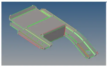
3.The topo mode view shows the surface irregularities in the imported model it should be cleared before the mid surface of the model is obtained.
4.For missing surfaces, the filler surf option under the quick edit tab is used.
5.For disconnected edges the toggle edge option under the quick edit tab is used.
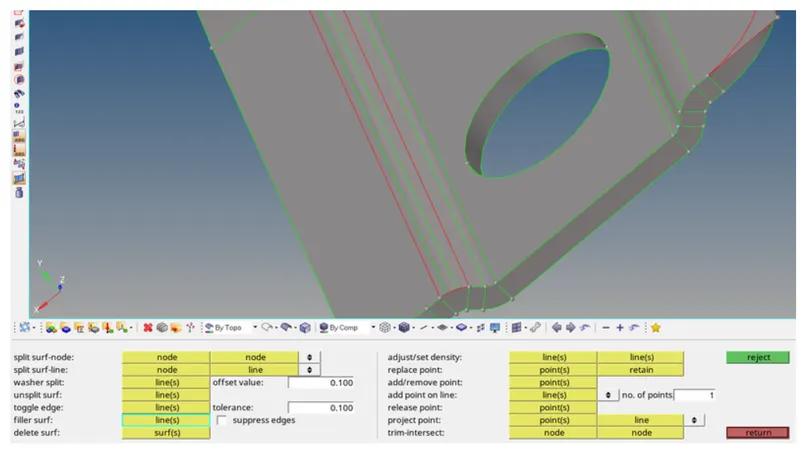
6.To extract midsurface, the midsurface is available in the geometry pannel.
7.After opening the midsurface tool the surfaces should be selected and the option used to extract the midsurface is offset+planes+sweeps. And the midsurface pannel.
8.To find out any surface fillet lead to minimum element size error and defature those fillets through the defature option.
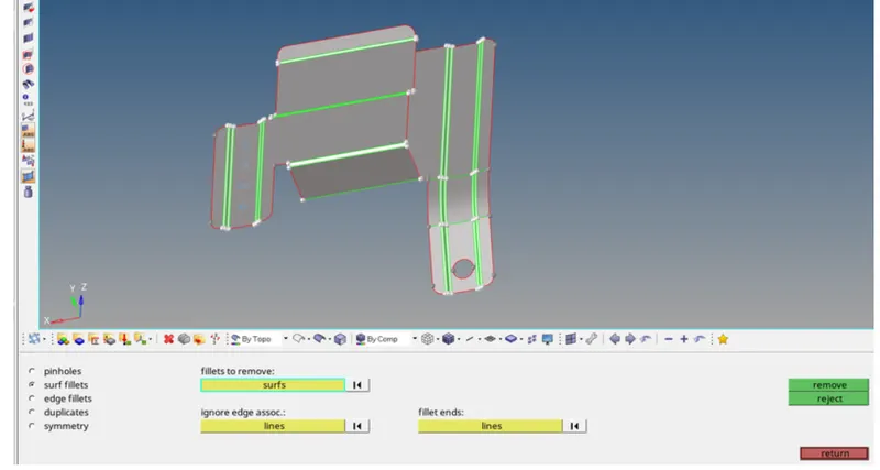
9.Some holes are noticed with a minute diameter. The radius can be founded by the Distance option. In that the distance with three nodes should be selected. And by placing the nodes on that free edges will show the radius of that hole. With the help of radius the diameter can be known.
10.After geometry clean up the next is generate the mesh. Before generating the mesh.
11.The given condition is applied in criteria editor.
12.The meshing is done by using auto mesh tool under the 2-D tab with elements size as 5 and elenment types as mixed.
13.The meshing of each component is done surface wise form one small surface.

14. The meshing is progressed into adjacent attached surfaces to mesh the whole model.
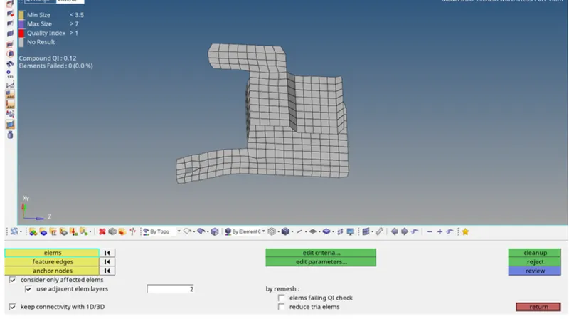
15.The meshed elements of all components are checked using the quality index tool.
16.The elements violating the specified quality criteria are marked in yellow and red.
17.Cleanup tools like element optimize and place node within the quality index is used to optimize the violating elements.
18.For elements that are not optimized to within the criteria range with the quality index tool the elem cleanup tool is used.
19.To check the free edges. The shortcut for that is shift+F3. By entering into the edges panel selecting the component and click on Find Edges. The free edges are obtained.
20.To chech for Normals. The normals option is avaliable in the tool panel. After entering into the normal option all elements are selected.
21.To assign thickness, a property need to be created. Property can be created by right clicking on the Tab bar. And the created property can be reneamed for easy understanding appears in the tab bar.
22.After creating a property by clicking on it the parameters with respect to that property.
23.The next step is to assign the property to the mid surface component where the elements are present. Assigining can be done by right clicking on the component to which the thickness should be assigned.
24.The final component after assiging the thickness.
PART-II: Clip Repair
1.Import the model
2.The given model is viewed in topo mode to view the surface edge.
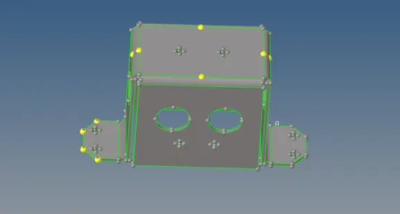
3.The midsurface of the closed solid is extracted using the surface edit tool under the geometry tab.
4.The midsurface is used to obtain the midsurface with an offset option.
5.Midsurface generated is stored under an initial collector. We need to move to another component.
6.There are some regions that have which leads to violation of quality criteria. This can be overcome by replacing those points.
7.This replacement option is available in the quick edit panel.
8.The meshing is done by using auto mesh tool under the 2-D tab with elements size as 5 and elenment types as mixed.
9.The meshing of each component is done surface wise form one small surface.
10. The meshing is progressed into adjacent attached surfaces to mesh the whole model.
11.The meshed elements of all components are checked using the quality index tool.
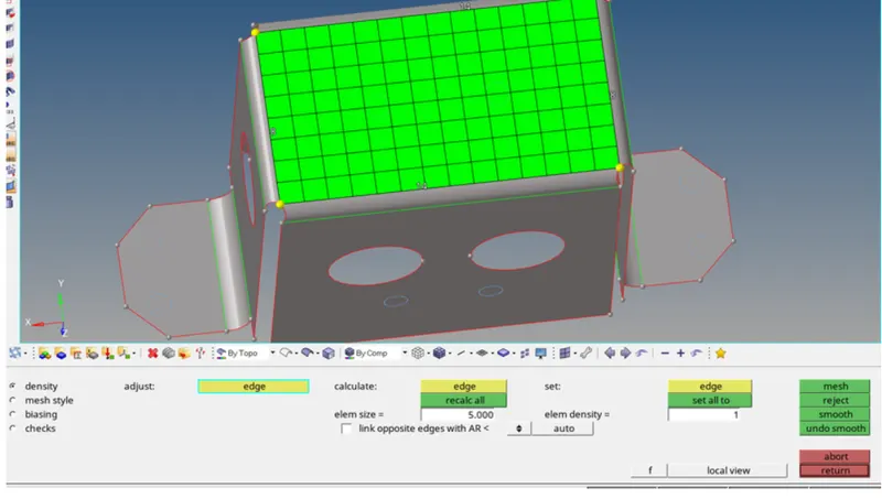
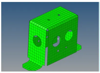
12.Even though the component is meshed fully there will be a gap and no connectivity between the nodes. This can be noticed by the option Find Edges.
13.The next step is to verify the free edges. It is also verified by the find edge option.
14.The next step is to verify the normals. The normals are checked in the same way as done for component.
15.The next step is to assign the thickness. For assigning the thickness a property is created and the thickness value with respect to the parent geometry is entered.
PART-III: Mounting Bracket
1.Import the model
2.The given model is viewed in topo mode to view the surface edge.
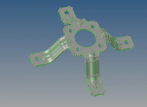
3.The midsurface of the closed solid is extracted using the surface edit tool under the geometry tab.
4.The midsurface is used to obtain the midsurface with an offset option.
5.Midsurface generated is stored under an initial collector. We need to move to another component.
6.There are some regions that have which leads to violation of quality criteria. This can be overcome by replacing those points.
7.This replacement option is available in the quick edit panel.
8.The meshing is done by using auto mesh tool under the 2-D tab with elements size as 5 and elenment types as mixed.
9.The meshing of each component is done surface wise form one small surface.
10. The meshing is progressed into adjacent attached surfaces to mesh the whole model.
11.The meshed elements of all components are checked using the quality index tool.

12.Even though the component is meshed fully there will be a gap and no connectivity between the nodes. This can be noticed by the option Find Edges.
13.The next step is to verify the free edges. It is also verified by the find edge option.
14.The next step is to verify the normals. The normals are checked in the same way as done for component.
15.The next step is to assign the thickness. For assigning the thickness a property is created and the thickness value with respect to the parent geometry is entered.
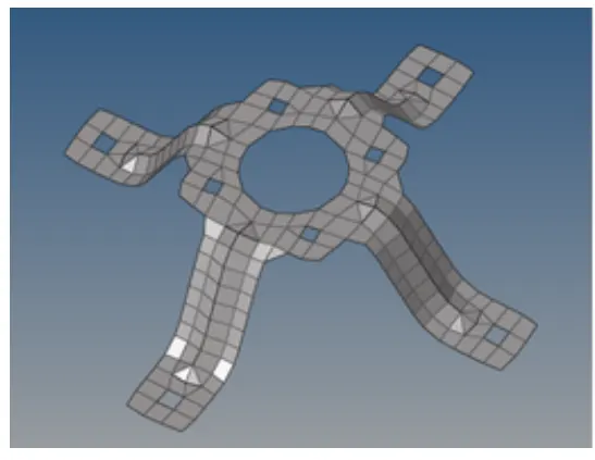
OBSERVATION: Thus the,
1.Extracted the midsurface and performed the geometry cleanup on the given components.
2.Generated a 2D mesh on the given components by following element quality criteria.
3.Finally, assign the thickness for the given components.
RESULT:
The given models were refined midsurfaced and meshed as per the given requirements. In additon to that, good mesh quality and flow was upheld as much as possible and the generated mesh was assigned a thickness according to that the parent geomtery.