Assignment 1-2D Meshing Challenge
Assignment 1-2D Meshing Challenge
Objective: Checking and performing the geometry cleanup for the given three models, extracting the mid surfaces, 2D meshing of the extracted mid surfaces using the given quality criteria and assigning the thickness to the created mesh.
Given Models:
- Case 1:- Part 1
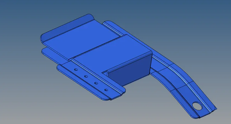
- Case 2:- Mounting Bracket
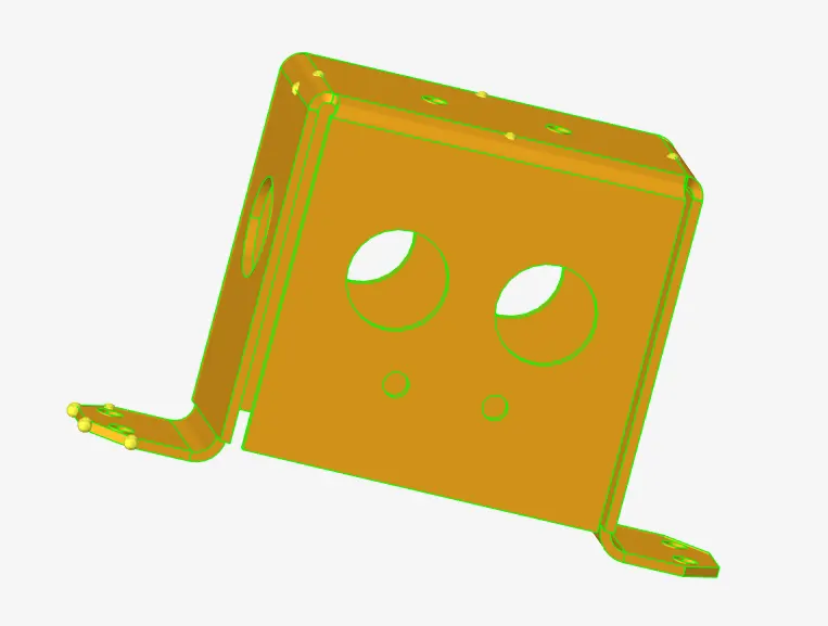
- Case 3:- Clip
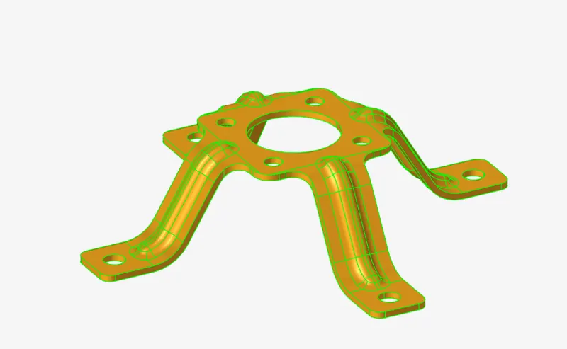
Given quality criteria:
|
S.No |
Quality Criteria |
Value |
|
1 |
Target Length |
5 mm |
|
2 |
Minimum Length |
3.5 mm |
|
3 |
Maximum Length |
7 mm |
Case 1 Setup and Execution:
- Opening the model and geomtery clean up
Intially Opening Hyperworks and opening Part 1 from File -> Open -> Model
After opening it, the model will appear without differantiating boundaries and to check if there any geometry clean up to be done the, the geomtery color mode is changed from Auto to mixed.
After changing geomtery color mode to mixed and switching on wire frame geomtery
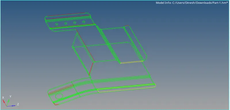
From this we can see the red line and yellow line which represents where geometry clean up is to be done.
- This is done using Quick Edit in Geometry panel, where we can toggle these red line by adjusting the tolerance value
- The areas where surfaces are missing is cleaned using filler surf from quick edit.
- The area marked has an additional surface which is to be removed and this is done by Surface Edit option-> trim with surfs -> self intersecting surfaces and selecting the adjacent surfaces to the red line in the marked area and using Tool -> delete option we can delete this extra surface.
- The yellow line represents the line is in contact with three surfaces and by deleting the additional surface the clean up of theses yellow lines are done.
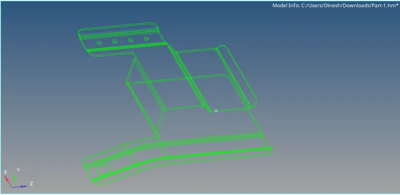
After geometry cleaning is done the model is shown below.
- Extracting the mid surface
After the geometry clean up is done the mid surface extraction is done by using midsurface option from geomtry panel.
Selecting the surfs by displayed and confirming it mid surface is generated as different component
extracted midsurface of the case 1:
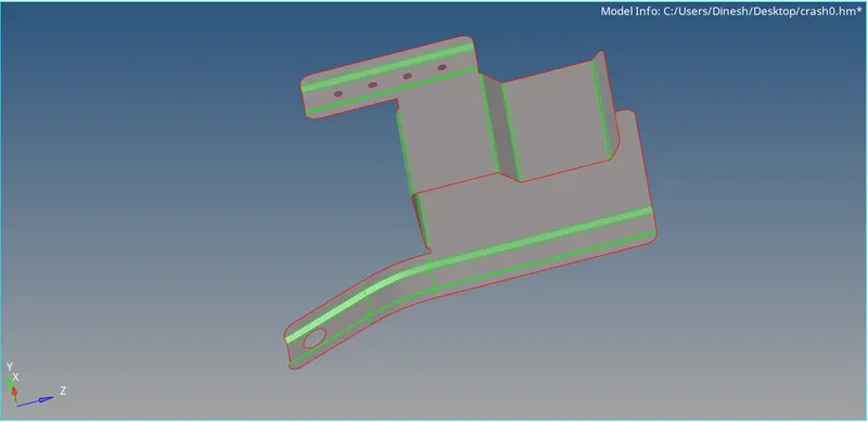
The extracted midsurface might has some areas which fails the given mesh quality criteria. So we need to defeature them.
- Defeaturing the mid surface
Since the given min length of the element is 3.5 mm, the fillets with less the than given elemental length is defeatured using deafeature -> surf fillets -> find fillets in selected surfaces, giving the minimum and maximum value of the surface and selecting the whole mid surface and confirming it.
The fillets in the given range are identified and by confirming, the fillets are defeatured.
After defeaturing
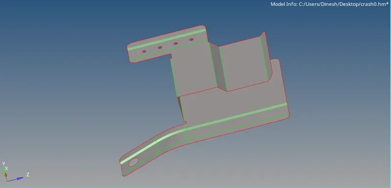
After the fillets are defeatured, the areas where quality might fail are suppresed using toggle option from quick edit option.
To capture the features, a mid line is generated between the toggled lines using surface split surf node-node.
This nodes required for splitting can be generated using add point on line.
The holes with less than 5mm diameter are filled suing filler surf from quick edit.
Additional points which are not on lines are toggled as they interfere with meshing quality.
- 2D Meshing
After cleaning the midsurface, 2D meshing is done using Automesh from 2D panel.
Selecting the surfaces and choosing element size to be 5 and confirming it the surfaces are meshed.
After meshing is done, The quality of the mesh is checked from quality index option for min length and max length.
The elements which are failing are rectified one by one using various options
Rebuild mesh, element optimize from quality index cleaup tools.
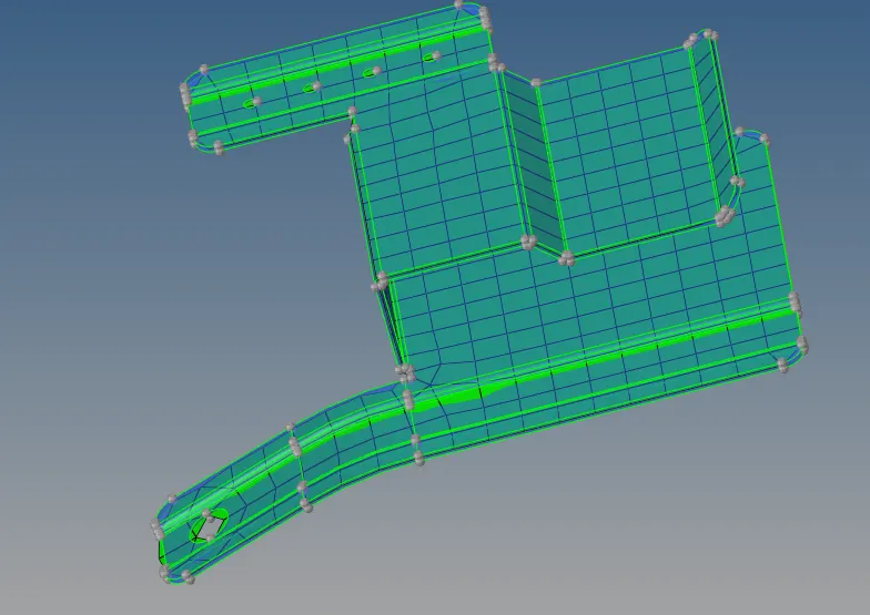
Meshed model is shown below.
- Assigning thickness to the model
After meshing is done, the thickness is assigned to the mid surface component by editing property card and giving thickness value in 0.91 mm.
This thickness for shells are actived by switching from 2D traditional element represeantation to 2D Detailed Representation
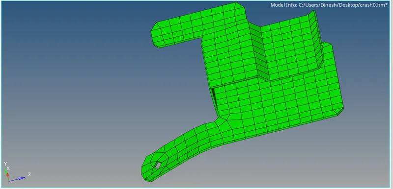
Case 2 Mounting Bracket Setup and Execution:
- Opening the model and geomtery clean up
Intially Opening Hyperworks and opening Part 1 from File -> Open -> Model
After opening it, the model will appear without differantiating boundaries and to check if there any geometry clean up to be done the, the geomtery color mode is changed from Auto to mixed.
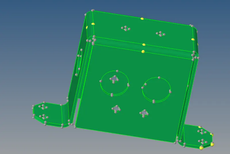
After changing geomtery color mode to mixed and switching on wire frame geomtery
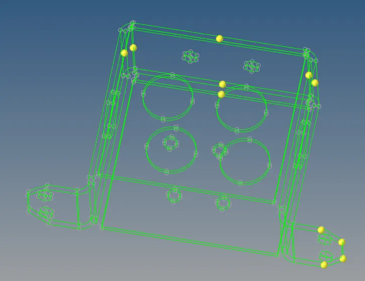
The model has no geometrical errors and so geomtery is clean.
- Extracting the mid surface
After the geometry clean up is done the mid surface extraction is done by using midsurface option from geomtry panel.
Selecting the surfs by displayed and confirming it mid surface is generated as different component
extracted midsurface of the case 1:
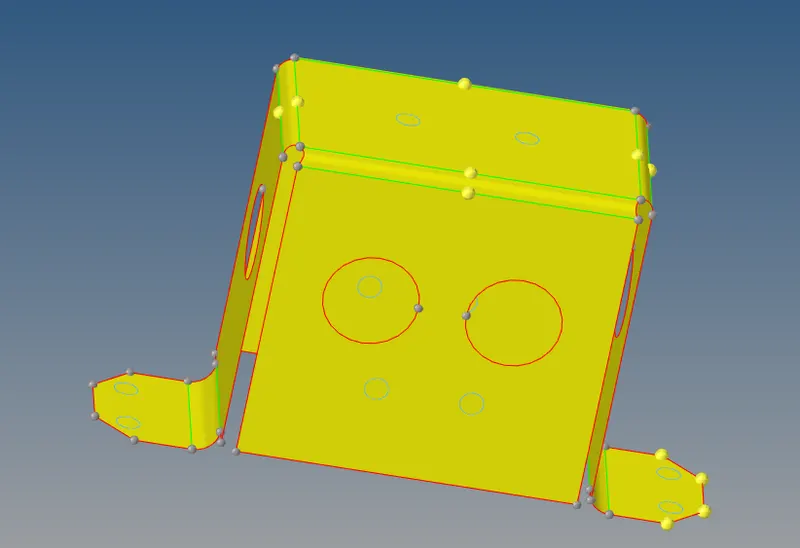
The extracted midsurface might has some areas which fails the given mesh quality criteria. So we need to defeature them.
- Defeaturing the mid surface
The holes with less than 5mm diameter are filled suing filler surf from quick edit.
Additional points which are not on lines are toggled as they interfere with meshing quality.
- 2D Meshing
After cleaning the midsurface, 2D meshing is done using Automesh from 2D panel.
Selecting the surfaces and choosing element size to be 5 and confirming it the surfaces are meshed.
After meshing is done, The quality of the mesh is checked from quality index option for min length and max length.
The elements which are failing are rectified one by one using various options
Rebuild mesh, element optimize from quality index cleaup tools.
Meshed model is shown below.
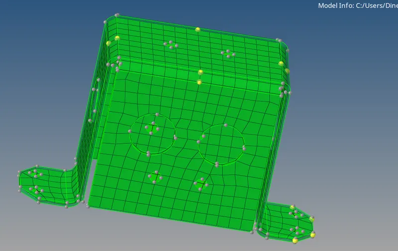
- Assigning thickness to the model
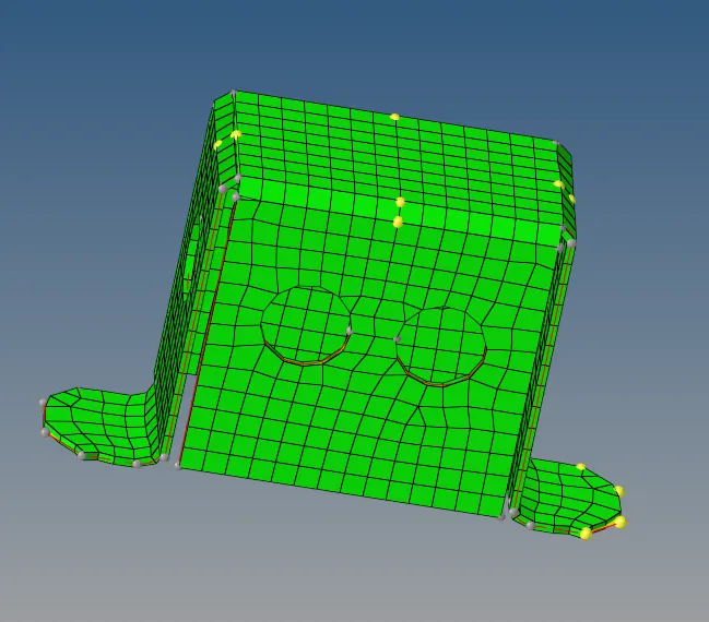
After meshing is done, the thickness is assigned to the mid surface component by editing property card and giving thickness value in 2 mm.
This thickness for shells are actived by switching from 2D traditional element represeantation to 2D Detailed Representation
Case 3 Clip Setup and Execution:
- Opening the model and geomtery clean up
Intially Opening Hyperworks and opening Part 1 from File -> Open -> Model
After opening it, the model will appear without differantiating boundaries and to check if there any geometry clean up to be done the, the geomtery color mode is changed from Auto to mixed.
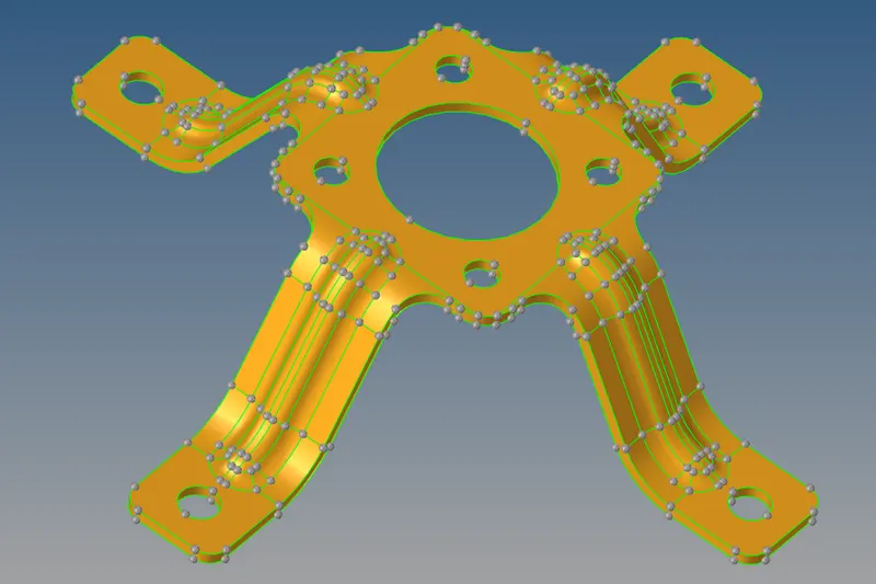
After changing geomtery color mode to mixed and switching on wire frame geomtery
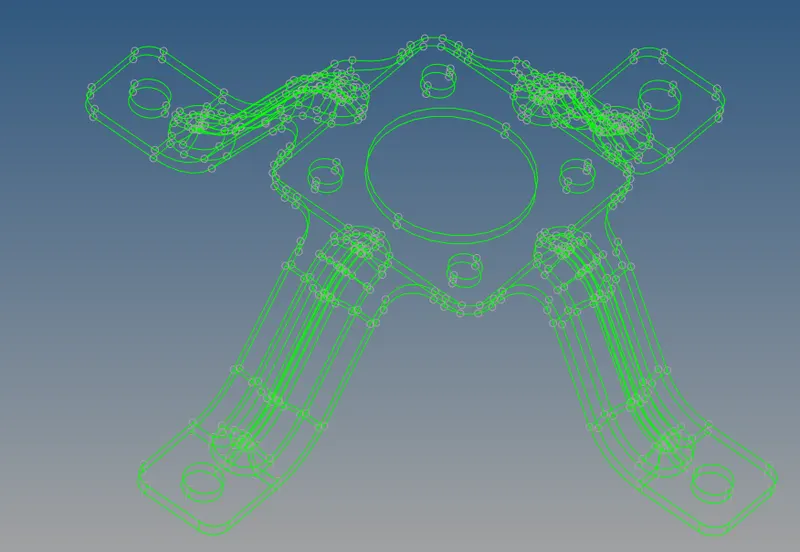
The model has no geometrical errors and so geomtery is clean.
- Extracting the mid surface
After the geometry clean up is done the mid surface extraction is done by using midsurface option from geomtry panel.
Selecting the surfs by displayed and confirming it mid surface is generated as different component
extracted midsurface of the case 1:
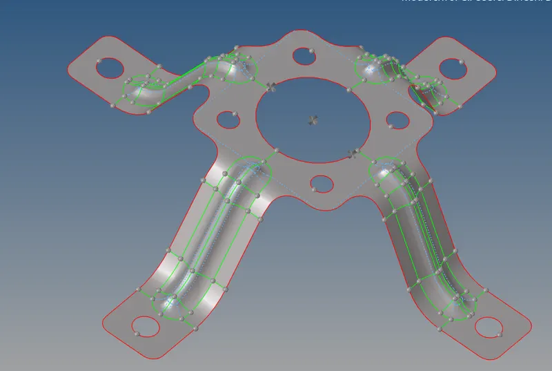
The extracted midsurface might has some areas which fails the given mesh quality criteria. So we need to defeature them.
- Defeaturing the mid surface
Since the given min length of the element is 3.5 mm, the lines which have distance less than 3.5 mm are toggled from quick edit option for one side as the given model has same features on four sides.
Additional points which are not on lines are toggled as they interfere with meshing quality.
- 2D Meshing
After cleaning the midsurface, 2D meshing is done using Automesh from 2D panel.
Selecting the surfaces and choosing element size to be 5 and confirming it the surfaces are meshed.
After meshing is done, The quality of the mesh is checked from quality index option for min length and max length.
The repeated feature is only meshed once and is duplicated and rotated using rotate from 2D panel. Here the elements and rotate angle is selected and confimed.
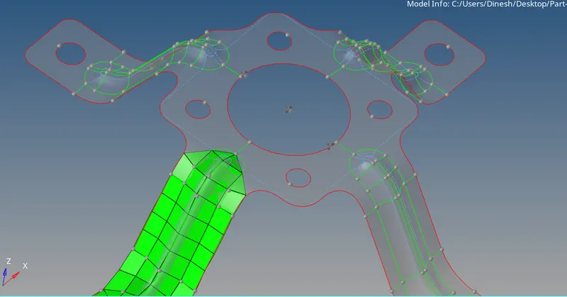
After the elements are rotated on all the similar feature these features nodes are then projected on the features of mid surface using lines using too -> project -> nodes
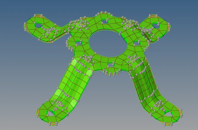
The elements which are failing are rectified one by one using various options
Rebuild mesh, element optimize from quality index cleaup tools.
Since this model mesh is done using rotate option the element connectivity may have some issues, this is checked using Tools-> edges and selecting the elements and confirming it with find edges the errors are shown.
These are rectified using 2D-> replace and selecting the nodes which are pasted together then.
After errors are rectified the edges are deleted.
- Assigning thickness to the model
After meshing is done, the thickness is assigned to the mid surface component by editing property card and giving thickness value in 1.8 mm.
This thickness for shells are actived by switching from 2D traditional element represeantation to 2D Detailed Representation
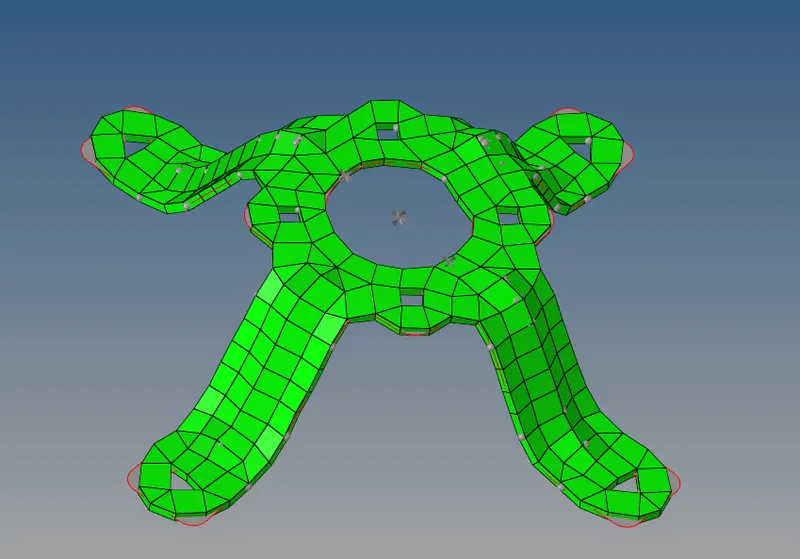
Results:
Part 1:
Mounting Bracket:
Clip:
Conclusion:
Checking and performing the geometry cleanup for the given three models, extracting the mid surfaces, 2D meshing of the extracted mid surfaces using the given quality criteria and assigning the thickness to the created mesh is done using Hypermesh 21.0.