Assignment 1
Exploring GT SUITE and Intercooler Simulation
1.Explore the GUI of GT SUITE and list down modules available with brief description.
GT Suite is a multiphysics CAE system simulation software. The foundation of GT Suite is a versatile multi-physics platform for constructing model of general system based on many underlying fundamental libraries:
- Flow library (any fluid, gas or liquid or mixture)
- Acoustics library (both linear and non-linear)
- Thermal library (all types of heat transfer)
- Mechanical library (kinematics, multi-body dynamics, frequency domain)
- Electric and Electromagnetic library (circuits, electromechanical devices)
- Chemistry library (chemical kinetics)
- Controls library (signal processing) Built in 3-D CFD
- 3D FE (thermal and structural)
There are three branches in which all these fall under, namely:
Template provides all the unfilled attributes required by the models.
Objects are made from templates which contain all the required parts.
Parts are the ones which are dropped onto the map.
1.1 MODULES
Some of the modules used in modeling engines are mentioned as follows:
MECHANICAL:
In this module we have all the components of transmission. The parameters for size, shape and the required mechanisms are altered for simulating.
THERMAL:
Essential components for heat transfer are needed to be imparted for running our system effectively and efficiently.
ELECTROMAGNETIC:
Electric and magnetic components needed for transmitting and receiving signals, with need for charging and storing energy through essential devices are modeled here.
CONTROL:
Sensors and detectors are used to measure the output performance of the product being controlled, these measurements are used to provide corrective feedback to help and achieve desired performance.
2.Locate following settings
2.1 TIME CONTROL FLAG
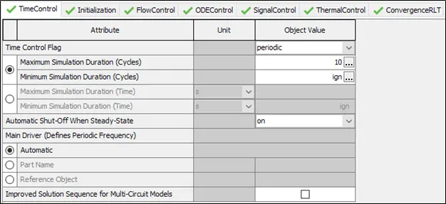
As the name implies it is used for denoting the simulation duration and also the variables for controlling the time.
The events can either be periodic (requires tracking based on varying angles) or continuous (no tracking).
The simulation time can be expressed either in cycles or in seconds based on our need.
2.2 TIME STEP AND SOLUTION CONTROL
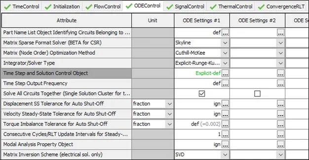
The numerical parameter for the explicit and implicit solver can be defined in this process.
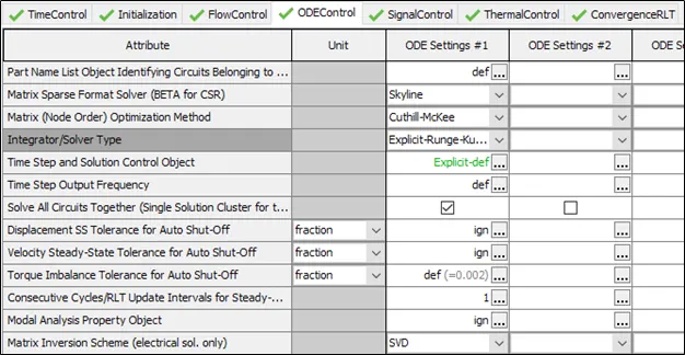
2.3 INTEGRATOR/SOLVER TYPE:
This is used in the time marching of ODE’s which is present in libraries.
3.Explore intercooler tutorial and note down all settings of
3.1 RUN SETUP
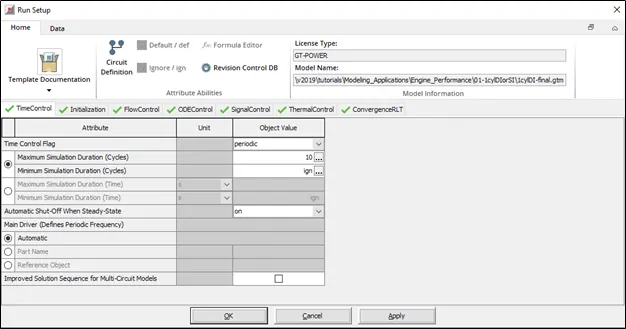
3.2 ADVANCED SETUP:

3.3 PLOT SETUP
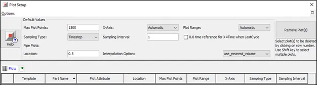
3.4 OUTPUT SETUP
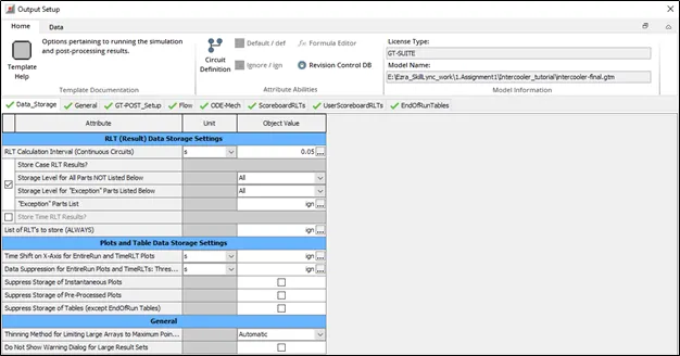
4.PROBLEM
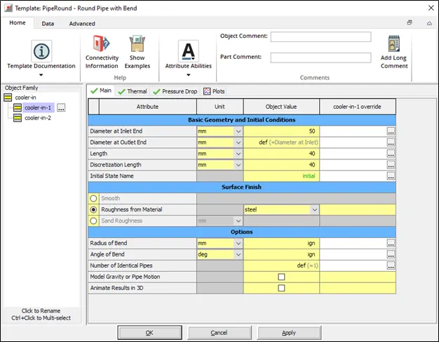
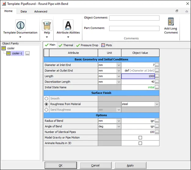
Diameter of cooler inlet and outlet pipe= 50 mm
Length of the CAC= 1000 mm
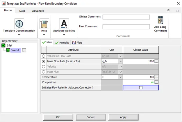
Inlet mass flow rate = 1200 kg/ h at 100 degC
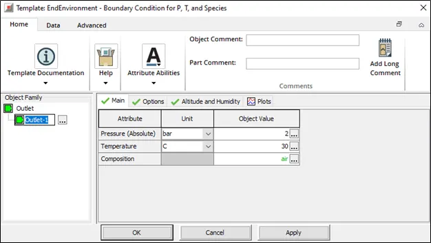
Outlet pressure 2 bar at 30 deg C
Total heat transfer at Charge air cooler (CAC)= 8.7317 kW
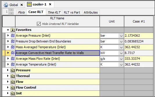
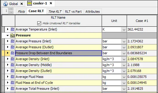
Pressure drop across CAC = 0.08368 Bar