Assembly of Yacht
OBJECTIVE:
To design each and every component of Sunseeker Yacht by using solidworks and giving realistic look by Solidworks visualize.
INTRODUCTION:
A yacht is a sail or power vessel used for pleasure, cruising, or racing. There is no standard definition, so the term applies to such vessels that have a cabin with amenities that accommodate overnight use. To be termed a yacht, as opposed to a boat, such a pleasure vessel is likely to be at least 33 feet (10 m) in length and have been judged to have good aesthetic qualities.
PLAN OF ACTION FOR YACHT DESINGING:
- Desingning of Parts/Components
- Assembly of Designed Components/Parts.
- Applying Decals, Camera setup & Scenes.
- Final Rendering.
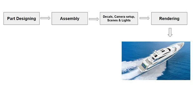
- Desingning of Parts/Components:
Sunseeker Yacht comprise of 9 Parts.
- Radar
- Propeller
- Hull
- Garage Door
- Front seat
- Middle seat
- Rear seat
- Super structure
- Radar mast
Radar :
A system for detecting the presence, direction, distance, and speed of aircraft, ships, and other objects, by sending out pulses of radio waves which are reflected off the object back to the source.
No. of Solid bodies : 1
Feature Tools : Extruded Boss/Base, Extruded cut, Sketch Driven pattern, Mirror, Fillet & Split line.
Sketch Tools : Sketch Geometry like Line, Circle.,Point, Text & Convert Entities.
Render Image : Photo view 360.
- Extruded Boss/Base- Extrudes a sketch or selected sketch contours in one or two directions to create a solid feature.
- Extruded Cut - Cuts a solid model by extrduing a sketched profile in one or two directions.
- Fillet - Creates a rounded internal or external face along one or more edges in solid or surface feature.
- Sketch Driven Pattern - Sketch Driven Patterns Using sketch points within a sketch, you can specify a feature pattern. The seed feature propagates throughout the pattern to each point in the sketch. You can use sketch driven patterns for holes or other feature instances.
- Mirror - Mirror features,faces and bodies about a face or a plane.
- Convert Entities - Converts selected model edges or Sketch entities into Sketch segments.
- Split line - Exceptionally useful for splitting faces without creating new surface bodies or trimming.
PROCEDURE:
- Right Plane - Draw a Trapezium using lines & extrude it.
- Sketch on Face of previous extrude by converting sketch 1 entities & extrude it.
- Sketch on Face of Sketch 1 extrude by drawing a circle at adistance of 60mm from lower edge converted entity & extrude it.
- Draw a circle on Previous Extrude face and do cut extrude.
- Use Sketch point to locate the previous extrude at required place and do sketch pattern.
- Now mirror across Right Plane.
- Draw a circle at lower egde of Radar face & do cut extrude.
- Sketch on Outer face of Radar using line, insert text as of choice and split across line.
- Finally give Appearance to it.
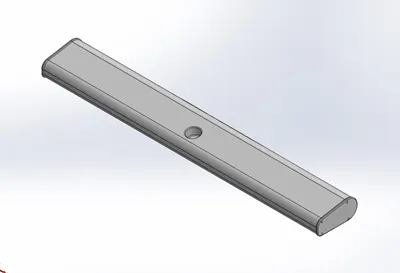
Fig (i) Solidworks Image
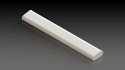
Fig(ii) Render Image
Propeller :
A mechanical device for propelling a boat or aircraft, consisting of a revolving shaft with two or more broad, angled blades attached to it.
No. of Solid bodies : 1
Feature Tools : Revolved Boss/Base, Extruded cut, Fillet & Circular Driven pattern.
Sketch Tools : Sketch Geometry like Line, Spline, 3 Point corner rectangle & circle.
Surface Tools : Lofted Surface.
Render Image : Photo view 360.
- Revolved Boss/Base - Revolves a sketch or selected sketch contours around an axis to create a solid feature.
- Lofted Surface - Creates a lofted surface between two or more profiles.
- Circular Driven Pattern - Patterns features, faces and bodies in circular direction.
PROCEDURE:
- Right Plane - Draw 2 horizontal lines, 1 vertical ine & a spline connecting left end points of horizontal lines and revolve it.
- Create a new plane, Top plane as reference at an offset of 360mm.
- Top Plane - Draw a 3 point rectangle at an angle of 74degreedegreefrom bottom edge of revolve.
- New Plane - Draw one more 3 point rectangle at an angle of 14 degree from similar edge.
- Using above two skeches create a loft surface & apply fillet.
- Draw a circle on bottom face of revolve and do cut extrude, apply fillet.
- Do circular pattern of above above features in feature scope with 6 no. of instances.
- Give Appearance to the part of light red colour changing RGB values to 71/45/0.
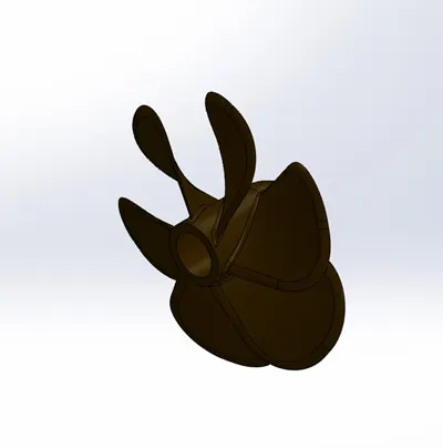
Fig (i) Solidworks Image
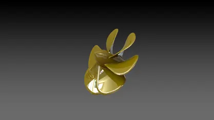 Fig(ii) Render Image
Hull :
A hull is the watertight body of a ship or boat. The hull may open at the top (such as a dinghy), or it may be fully or partially covered with a deck. Atop the deck may be a deckhouse and other superstructures, such as a funnel, derrick, or mast. The line where the hull meets the water surface is called the waterline.
No. of Solid bodies : 1
No. of Surface bodies : 3
Feature Tools : Revolved Boss/Base, Extruded cut, Projected curve, Split line, Shell, Copy, Delete faces, Extruded Bos/Base, Mirror,
Helix, Swept Boss/Base, Chamfer, Fillet & Linear Driven pattern.
Sketch Tools : Sketch Geometry like Line, Spline, rectangle, fillets, Straight slot & circle., Trim, Convert, Extend & Offset Entities.
Surface Tools : Lofted Surface,Extend Surface, Filled Surface, Extruded Surface, Trim Surface & Knit.
Render Image : Photo view 360.
- Projected curve - Creates a 3D curve using two 2D sketches.
- Shell - Removes a material from a solid body to create a thin-walled feature.
- Delete faces - Deletes faces from solid bodies to create surfaces or deltes faces from a surface bodies.
- Swept Boss/Base - Sweeps a closed profile along n open or closed path to create a solid feature.
- Trim Entities - Trims a sketch entity to be coincident to another or deletes a sketch entity.
- Offset Entities - Adds sketch entities by offsetting faces,edges,curves or sketch entities a specified distance.
- Convert Entities - Converts selected model edges or sketch entities into sketch segments.
- Extend Surface - Extends the edge, multiple edges or the face on a surface based on end conditions and extension type.
- Filled Surface - Constructs a surface patch within a boundary defined by existing model edges,sketches or curves.
- Extruded Surface - Creates an extruded surface.
- Trim Surface - Trims a surface where one surface intersects with another surface, a plane or a sketch.
- Knit Surface - Combines two or more adjacent, non-intersecting surfaces together.
PROCEDURE:
- Blue Print setup - Insert all views like Top view, Side view, bottom view, front view,etc.. by giving proper X,Y & Z direction dimensions to it.
- Create two new planes Back Plane and Top Plane using Front & bottom plane as references.
- Bottom Plane - Draw a Horizontal line and a spline with midpoint, give relations and dimensions to make it fully defined.
- Mid Plane - Draw a Inclined line in -z direction, vertical centerline and a spline with 2 midpoints, drag the arrows to make sure it matches blue print.
- Create a Projected curve using above two sketches.
- Similarly create one more projected curve by drawing sketches on Mid plane & Bottom Plane using lines and splines.
- Back Plane - Draw a spline and use pierce relation to connect with projected curve.
- Mid Plane - Draw one more spline and use pierce relation again.
- Now create a lofted surface using above two sketches.
- Similarly create one more surface loft by drawing sketches on Midpland and Back Plane using splines.
- Inorder to trim extra surface draw a vertical line in Midplane and trim extra portion.
- Mid Plane - Draw a spline parallel to surface loft and do surface loft.
- Mid Plane - Draw a horizontal line and vertical line do surface extrude.
- Trim Extra surfaces an knit them together.
- Make sure all lines turn out to black colour which indicates proper knitting.
- Inorder to fill the gap use Filled surface by drawing a sketch on Mid Plane.
- Now Knit Surfaces and create Shell.
- Mid Plane - Offset created surface entities inwards and draw a line to make closed surface. Trim extra entities using Trim entities and extrude it.
- Bottom Plane - Draw a sketch using 2 splines and do cut extrude.
- Apply Fillets and Chamfers to respective edges.
- For Side Windows - Draw four lines as a rectangle on Plane 1 and apply fillets to corners, do linear pattern. Remove extra created Window and create a cut extrude.
- For Porth holes - Draw a straight slot on Plane 1, copy the slot to another port hole using copy feature as per blue print & do cut extrude. Create a 2D Sketch in new plane by drawing a circle and for proflie create a 3D Sketches by converting porth holes entites. Now create a solid sweep. Repeat similar steps for creating remaining porth holes.
- For Lower Deck - Create a sketch on Top Plane as per Blueprint using Splines, lines and do extrude.
- For Stair case - Creat a sketch on Top Plane by drawing drawing line in rectangle shape and do cut extrude . Select the extruded right face and draw few connecting horizontal and vertical lines in the form of stairs, extrude it Upto next/Upto surface.
- For Lower Portion of Hull - Create a plane at an offset of 3000mm from Bottom Plane. Draw 3 splines and drag their arrows to match as per blueprint. Offset the splines and make it closed by drawing lines., extrude it.
- Anchor House - Draw a sketch on Top face of Hull using two circles and connect them with lines and trim the inner half of circle to create a lower suface of Anchor house. Draw a vertical line & hoorizontal line on new plane using previous sketch as reference and revolve it. Create a sketch by drawing lines and circles, extrude it. To remove some portion from previous extrude, create a skecth and do cut extrude.
- For Rope - Draw a helix and create a plane using helix as reference, draw a circle at the end point of helix. Using Helix as path and circle as profile do sweep. Create one more sweep to connect the rope from house to created helix.
- Create some extra porth holes at front end and rear endwith the help of few sketches and extrude them, use linear pattern accordingly to pattern them.
- For Handrailing - Create a new plane offset from left face of stair connected portion. Draw a sketch by 3 Point Center rectangle and apply fillets to two top corners. Create one more plane using lower left end point of rectangle and draw a circle. Now Sweep using Circle and rectangle as profile & path respectively.
- For Side Railing - Draw a sketch on Mid Plane by offseting inner edge of Hull inwards and outwards respectively. Draw few vertical lines as per blue print and trim the unwanted portion, so that it will form a chain. Apply fillets to end portion and draw one more sketch in respective plane where offset the inner edges of hull. Now create a projected curve using above two sketches. Create a new plane at the end of created sketch for railing reference and draw a circle., sweep by using circle and projected curve.
- For Caliper - Draw a sketch on Back Plane using few lines and extrude it, to develop caliper surface. Select the surface of Caliper draw a sketch as per per blueprint & revolve it.
- For Propeller Shaft - Create a sketch on Back face of Hull by drawing lines as per blue print and revolve it. Pattern it accordingly with the help of Pattern direction sketch.
- For Connecting Rod - Draw a 3D Sketch using line to connect both Propeller shaft holes & extrude it.
- For Anchor - Draw a sketch on Midplane at front portion of Hull using lines and splines as per blueprint and extrude it and mirror it across respective face.
- For Garage Door - Draw a sketch on Midplane by drawing a corner rectangle & do cut extrude. sketch extrude left face and sketch on it by coverting previous sketch as entities, create cut extrude. Now use split and remove the appropriate portion and save it as Garage door.
- Create a pin by drawing circle on previous extruded face, extude it.
- Create a new sketch on Mid Plane by drawing Splines and offset in upward and downward direction. Use Split line and select all faces to split.
- Now give appearance to Hull, windows, Railings, Caliper, Anchor,etc.,
- Finally mirror the whole body across Mid Plane and check all appearance are applied correctly.
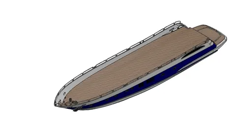
Fig (i) Solidworks Image
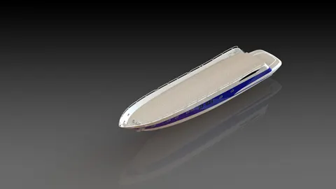
Fig(ii) Render Image
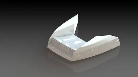
Front Seat :
Front Seat is loctaed at the front end of Hull which is usually used for seating and to enjoy the scenery.
No. of Solid bodies : 9
No. of Surface bodies : 1
Feature Tools : Revolved Boss/Base, Extruded cut, Fillet, Dome & Mirror.
Sketch Tools : Sketch Geometry like Line, Spline., Convert Entities.
Surface Tools : Lofted Surface, Swept Surface, Extruded Surface, Filled Surface, Trim Surface & Knit Surfaces.
Render Image : Photo view 360.
- Swept Surface - Creates a surface feature by sweeping an open or closed profile along an open or closed path.
- Dome - Creates one or more dome features simultaneously on the same model.
- Lofted Surface - Creates a lofted surface between two or more profiles.
PROCEDURE:
- Blue Print setup - Insert all views like Top view, Side view, bottom view, front view,etc.. by giving proper X,Y & Z direction dimensions to it.
- Create two new planes Back Plane and Top Plane using Front & bottom plane as references.
- Insert the Hull part by selecting the surface bodies.
- Create Swept Surface by creaating a sketch on Deck face by drawing a spline & another sketch on created plane by drawing a line.
- Draw two lines and connect with previously created surface sweep and Extrude the surface.
- Trim the Extra surface and fill the gap portion with Filled Surface.
- Draw few sketches accordindly to trim extra surfaces.
- Create Surface loft using above two sketches.
- Trim the Extra surfaces & Knit it together.
- Draw lines accordingly to create seat and revolve it about 10 degree.
- Apply Fillets and mirror the bodies.
- Finally Apply Dome to seats & give appearance.
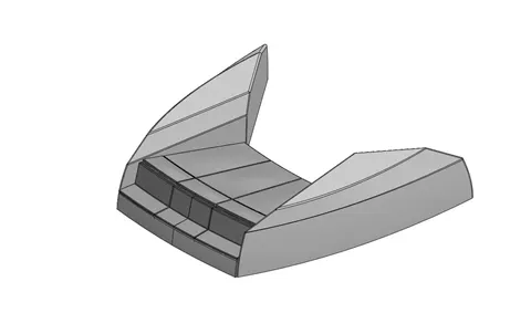
Fig (i) Solidworks Image
Fig(ii) Render Image
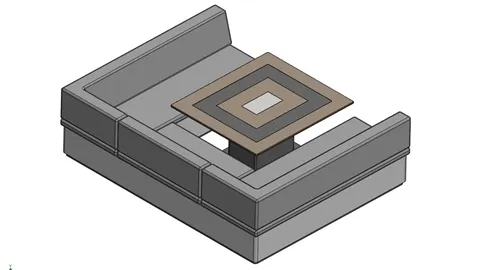
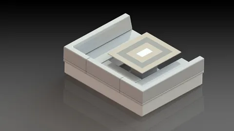
Middle Seat:
Middle seat is situated just after rear end of Super Structure which also used for Seating & Chilling out.
No. of Solid bodies : 8
No. of Surface bodies : 1
Feature Tools : Extruded Boss/Base, Extruded cut, Fillet & Mirror.
Sketch Tools : Sketch Geometry like Line, Convert Entities & Offset Entities.
Render Image : Photo view 360.
- Extruded Boss/Base- Extrudes a sketch or selected sketch contours in one or two directions to create a solid feature.
- Extruded Cut - Cuts a solid model by extrduing a sketched profile in one or two directions.
- Fillet - Creates a rounded internal or external face along one or more edges in solid or surface feature.
PROCEDURE:
- Blue Print setup - Insert all views like Top view, Side view, bottom view, front view,etc.. by giving proper X,Y & Z direction dimensions to it.
- Create two new planes Back Plane and Top Plane using Front & bottom plane as references.
- Insert the Hull part by selecting the surface bodies.
- Draw a L Shape using lines on face of deck and extrude for lower portion of seat.
- Create a sketch on above extrude face offset the face and extrude.
- Create a Plane on above extrude face by offsetting at a distance of 5mm. Sketch on it by drawing lines as per blueprint and extrude.
- Mirror the bodies across Mid Plane by selecting Knit Surfaces and merging solids.
- Mirror seats across Mid Plane by de-selecting Knit Surfaces and Merging solids.
- Create a Table by selcting deck face using lines and offest entities.
- Create a Cut Extrude at the top surface of the table and apply fillets.
- Finally give Appearance to Table & Seats.
Fig(i) Solidworks Image
Fig(ii) Render Image
Rear Seat :
Rear seat is situated at rear end of Hull which also used for Seating & Enjoying view.
No. of Solid bodies : 3
No. of Surface bodies : 4
Feature Tools : Extruded Boss/Base, Revolved Boss/Base, Extruded cut, Fillet, Chamfer & Mirror.
Sketch Tools : Sketch Geometry like Line, Spline., Convert Entities, Offset Entities & Trim Entities.
Surface Tools : Lofted Surface, Swept Surface,Offset Surface, Ruled Surface, Trim Surface & Knit Surfaces.
Render Image : Photo view 360.
- Offset Surface - Creates offset surface using one or more more contiguous faaces.
- Ruled Surface - Inserts ruled surfaces from edges.
- Trim Surface - Trims a surface where one surface intersects with another surface, a plane or a sketch.
- Knit Surface - Combines two or more adjacent, non-intersecting surfaces together.
PROCEDURE:
- Blue Print setup - Insert all views like Top view, Side view, bottom view, front view,etc.. by giving proper X,Y & Z direction dimensions to it.
- Create two new planes Back Plane and Top Plane using Front & bottom plane as references.
- Insert the Hull part by selecting the surface bodies.
- Mid Plane - Draw 2 Splines as per Blueprint dimension it to make full define.
- Create a Plane using Deck face & vertex of spline as references.
- Create one more sketch on new plane by drawing a spline.
- Now using above two sketches do Surface Sweep.
- Create a offset surface of previous sketches by selcting respective faces.
- Trim the Extra Surface by drawing sketches accordindly.
- Use Ruled Surface to extend the surface and Knit everything.
- Draw a sketch on Plane 1 using Splines which is used to trim surface.
- Create few Planes and draw sketches by cusing convert entities and splines. Do Surface sweep using these sketches.
- Extend the Surface and trim the unwanted surafces using surface trim and Knit them.
- Create few 3D Sketches and do surface loft.
- Create a sketch on deck face by converting respective entities and spline with midpoint, Extrude it.
- For Hand resting - Create a Sketch on Previous Extruded face by selecting face and convert entities. Draw few lines as per blue print and trim extra entities, Extrude it.
- For Doors/Drawers - Create a cut extrude by drawing a lines on Front Plane.
- Offset the appropriate faces for creation of Seats. Trim the surfaces by keeping the selectionto split the surfaces.
- For Upper Seats -Create a Boss Extrude by drawing Sketch on offset surface using convert entities and line. Apply Chamfer and fillets accordingly.
- For Lights - Create a sketch on Plane 4 by drawings and extruding line.
- For Locking Gates - Create few planes as per requirement and draw sketches accordingly using circle and line. Using these sketches sweep and mirror it.
- Mirror the Bodies across Mid Plane by Selecting Knit Surfaces & Merge solids.
- Mirror seats and gates across Mid Plane separtely by deselecting Knit Surfaces & Merge solids.
- For Flag Stand - Create a sketch on Mid Plane by drawing lines at an angle and revolve it.
- For Flag - Create four 3D Sketches by drawing spline with midpoints in each sketch and loft the surface.
- Finally Give Appearance to Seats, Lower Surface, Flag, Hand resting, Lights, Drawers & Gate.
Garage Door:
Garage Door which is usually used to park vehicles inside Yacht.
No. of Solid bodies : 1
Feature Tools : Extruded cut, Fillet, Text, Shell & Mirror.
Sketch Tools : Sketch Geometry like Line, Circle.
Render Image : Photo view 360.
- Extruded Boss/Base- Extrudes a sketch or selected sketch contours in one or two directions to create a solid feature.
- Extruded Cut - Cuts a solid model by extrduing a sketched profile in one or two directions.
- Fillet - Creates a rounded internal or external face along one or more edges in solid or surface feature.
- Text - Creates a Text on Solid or Surface feature.
PROCEDURE:
- Open Garage Door part which was saved while designing Hull part.
- Create a sketch on right face of Stock by drawing lines and do cut extrude.
- Apply Shell by selecting faces of the stock.
- Draw a circle at the top by selcting side face of stock and do cut extrude to create a hole.
- Apply fillets & mirror across Right Plane.
- Create a plane using Front Plane as a reference by offseting it.
- Draw a sketch on created Plane by drawing Horzintal Center line and insert Text in Text box, do cut extrude.
- Finally give Appearance to Door and Text.
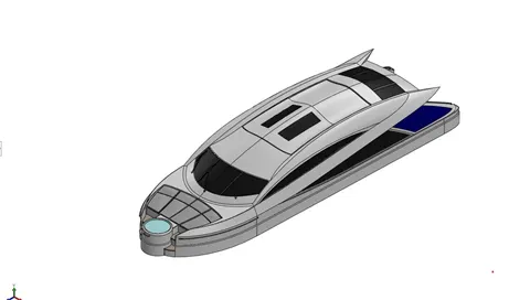
Super Structure :
A superstructure is an upward extension of an existing structure above a baseline. The size of a watercraft's superstructure can have many implications in the performance of ships and boats, since these structures can alter their structural rigidity, their displacements, and/or stability. These can be detrimental to any vessel's performance if they are taken into consideration incorrectly.
The height and the weight of superstructure on board a ship or a boat also affects the amount of freeboard that such a vessel requires along its sides, down to her waterline. In broad terms, the more and heavier superstructure that a ship possesses (as a fraction of her length), the less the freeboard that is needed.
No. of Solid bodies : 7
No. of Surface bodies : 2
Feature Tools : Extruded Bos/Base, Extruded cut, Projected curve, Split line, Delete faces, Mirror, Swept Boss/Base, Chamfer & Fillet
Sketch Tools : Sketch Geometry like Line, Spline, rectangle, fillets & circle., Trim, Convert & Offset Entities.
Surface Tools : Lofted Surface,Extend Surface, Filled Surface, Extruded Surface, Ruled Surface, Trim Surface & Knit Surfaces.
Render Image : Photo view 360.
- Projected curve - Creates a 3D curve using two 2D sketches.
- Delete faces - Deletes faces from solid bodies to create surfaces or deltes faces from a surface bodies.
- Swept Boss/Base - Sweeps a closed profile along n open or closed path to create a solid feature.
- Trim Entities - Trims a sketch entity to be coincident to another or deletes a sketch entity.
- Offset Entities - Adds sketch entities by offsetting faces,edges,curves or sketch entities a specified distance.
- Convert Entities - Converts selected model edges or sketch entities into sketch segments.
- Extend Surface - Extends the edge, multiple edges or the face on a surface based on end conditions and extension type.
- Filled Surface - Constructs a surface patch within a boundary defined by existing model edges,sketches or curves.
- Extruded Surface - Creates an extruded surface.
- Trim Surface - Trims a surface where one surface intersects with another surface, a plane or a sketch.
- Knit Surface - Combines two or more adjacent, non-intersecting surfaces together.
PROCEDURE:
- Blue Print setup - Insert all views like Top view, Side view, bottom view, front view,etc.. by giving proper X,Y & Z direction dimensions to it.
- Create two new planes Back Plane and Top Plane using Front & bottom plane as references.
- Insert the Hull part by selecting the surface bodies.
- Create a sketch on Deck Surface by drawing a two Splines and a line as per blueprint and extrude the surface.
- Create a Plane at the end of Create Surafe Extrude.
- Create a surface sweep by drawing sketches on created Plane using line (Horziontal) and apply pierce realtion with extruded surface. A 3D sketch by convetering Outer surface as entities.
- Extend the Outer edge of surface using Ruled surface at an angle and trim the extra surface. Knit all the surfaces.
- Create one more Projected Curve by drawingtwo sketches on respective Planes using Splines and lines which is further used in creating Lofted Surface.
- Create one more surface sweep by drawing sketches on created Plane using line (Horziontal) and apply pierce realtion with extruded surface. A 3D sketch by convetering Outer surface as entities.
- Trim the surfaces which are not required by drawing sketches on respective faces/Planes.
- Create a Swept Surface by drawing a sketch on Mid Plane using Splines and a 3D Sketch by converting respective edges.
- Trim the extra surfaces.
- Similarly for creation of surfaces on Top, draw two sketches on respective Planes to get Projected Curve as per Blue print which is further used to create Lofted Surface.
- For Side Windows - Select the outer surface of Super structure use Ruled surface for extension. Trim the Extra surfaces.
- Select the Deck face and create a sketch by drawing a line at rear portion and do Surface extrude. Trim extra surfaces and Knit all togther.
- For Front Portion - Draw a sketch on Mid Plane by converting respective edges and do surface extrude. Trim extra surfaces and Knit all togther. Create one more sketch on Mid Plane by drawing line and spline and do surface extrude.
- Select the deck surface and create a sketch sketch by drawing a circle at a distance from above surface extrude. Extrude it and draw a circle at on extruded face to perform cut extrude. Draw two more circles on extruded face which are again to be extruded. Apply fillets to respective edges. Inorder to remove extra portion draw a rectangle on deck surface do cut extrude. Use Delete face option to remove respective faces.
- For Steps: Draw few lines horizontal and vertical lines accordingly and extrude them. Trim the Extra Surfaces.
- Inorder to make it Solid, Sketch on deck surafce by drawing a horziontonal line and do surface extrude. Trim the extra surfaces and Create Solid by knitting the surfaces.
- FOR Mattress - Create a Surface Offset at Front end and Trim unwanted surface and thicken the surface by selecting respective faces. Create a cut extrude and apply domes and fillets to them.
- For Railing (Side and Front) - Create a sweep by drawing sketches on respective planes using circle and splines.
- For Door (at Rear end) - Create a cut extrude by offseting rear face inwards. Draw a L shape and extrude it for handle creation.
- For Front Glass - Create a Sketch on Top Plane by Offseting entities and do cut extrude.
- For Frames - Sketch on respective face by drawing two vertical lines and converting top and bottom edges of glass. Trim unwanted entities and do Extrude.
- For Top Glass- Create a sketch on Top Plane by drawing a line and Spline and do cut extrude.
- For Top Frames - Create a sketch by offseting resepective edges and remove unwanted entities usi ng Trim entities. Extrude it.
- Similarly create windows and frames for side faces by drawing few sketches and doing cut & Boss extrude respectively.
- For Rear portion , draw a sketch on Midplane Offseting respective face and do split line.
- For Wipers Holders - Create a Sketch on top face of Super structure by drawing one circle and half circle. Extrude them.
- Mirror the bodies across Midplane.
- For Radar Mast Reference - Create a Offset Surface by selecting rear portion of Top face of Super Structure and rename it.
- For Wipers - Create a Rectangle on respective palne and do Boss extrude. Repeat two more times at respective places. Apply Chamfer and offset the Side faces and do cut extrude. Similarly do it for remaining Wipers. Draw a 3D sketch by drawing a line connecting holder and wiper, extrude it whcih acts a connecting rod. Repeat for remaining ones.
- Give Appearance to windows, Doors, Frames, Mattress, Wipers, water, Railing and Superstructure.
Fig(i) Solidworks Image
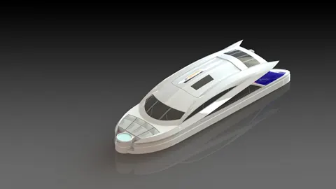
Fig(ii) Render Image
Radar mast:
Radar is a detection system that uses radio waves to determine the range, angle, or velocity of objects. It can be used to detect aircrafts, ships, spacecrafts, guided missile, motor vehicles, weather formation, and terrian. A radar system consists of a transmitter producing electromagnetic waves in the radio or microwaves domain, a transmitting antenna, a receiving antenna (often the same antenna is used for transmitting and receiving) and a receiver and processor to determine properties of the object(s). Radio waves (pulsed or continuous) from the transmitter reflect off the object and return to the receiver, giving information about the object's location and speed.
No. of Solid bodies : 2
No. of Surface bodies : 2
Feature Tools : Extruded Bos/Base, Revolved Boss/Base, Projected curve, Mirror, Swept Boss/Base, Chamfer & Fillet
Sketch Tools : Sketch Geometry like Line, Spline, rectangle, 3 point arc , Straight slot & circle.
Render Image : Photo view 360.
- Extruded Boss/Base- Extrudes a sketch or selected sketch contours in one or two directions to create a solid feature.
- Extruded Cut - Cuts a solid model by extrduing a sketched profile in one or two directions.
- Fillet - Creates a rounded internal or external face along one or more edges in solid or surface feature.
- Swept Boss/Base - Sweeps a closed profile along n open or closed path to create a solid feature.
- Mirror - Mirror features,faces and bodies about a face or a plane.
PROCEDURE:
- Blue Print setup - Insert all views like Top view, Side view, bottom view, front view,etc.. by giving proper X,Y & Z direction dimensions to it.
- Create two new planes Back Plane and Top Plane using Front & bottom plane as references.
- Insert the Super structure part by selecting the surface bodies.
- Create asketch on surface of radar mast by drawing a horizontal line at a distance of 160mm from surface and apply fillets to outer and inner edges.
- Draw 4 splines and a line as per Blue Print and extrude it on created plane.
- For Radar Indicators - Draw a sketch on Top face of Previous extrude using a line and 3 point arc., revolve it. Draw a circle on extruded face and extrude it. Apply fillets.
- For Antena - Create a Sketch on Extrude1 face by drawing a circle and extrude it. Draw one more circle on extruded face and extrude it. Do one more extrude on previous extrude face by drawing a circle.
- Create a sweep by drawing a sketch on created plane using spline and a circle on 3D sketch.
- Mirror above sweep across Plane 2 and connect them by drawing three circle on sweep and extrude them.
- Create a Projected curve as per requirement by drawing sketches on respective Planes.
- Create a Sweep by drawing a circle at the edge of projected curve.
- For Horn- Draw few lines and splines as per blueprint.,do revolve. Apply Dome to one end and shell to other end.
- Mirror Everything except Horn across Mid Plane.
- For Horn Support- Draw a straight slot on Extrude 1 face and extrude upto Horn Face.
- Create a Plane using above extruded right face and offset it. Mirror the Horn and its support across the created plane.
- Finally give Appearance to Radar mast, Antena, Horn & Indicators
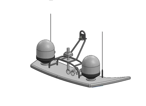
Fig(i) Radar mast
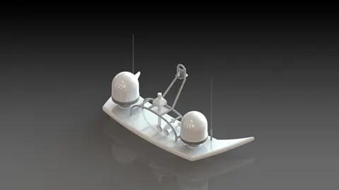
Fig(ii) Radar mast
Assembly of Designed Components/Parts :
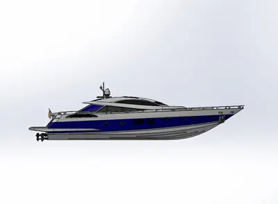
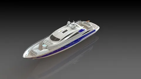
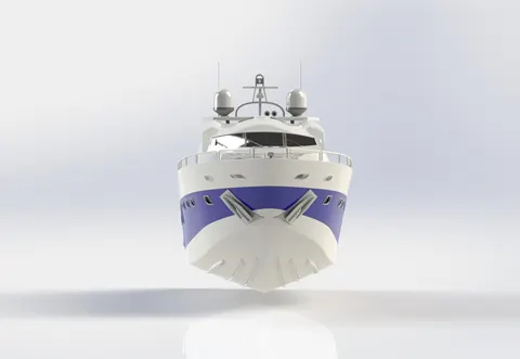
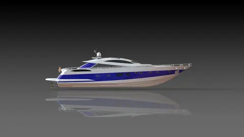
In this Portion all the designed individual components are assembled together for Sunseeker Yacht Design.
Steps to be followed for Assembling-
- All Designed Parts to be inserted one by one as per requirement.
- Apply Mate Conditions with respective parts for giving exact location in Assembly.
- In this assembly Only Rear seat, Radar and Propeller are to located using coincident and Concentric relations with respective Parts. Other Parts are already fixed (Using Surfaces as references) so no need of giving seperate mate conditions.
Render Image: Photo View 360
- Insert Component - Adds an existing part or sub-assembly to the assembly.
- Mates - Position two components relative to one another.
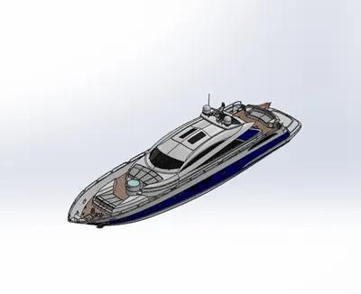
Applying Decals, Camera set-up & Scenes:
In this section Decals(Special designed Papers) are applied to
- Hull- Main Floor, Mood Board, Front end & stair case.
- Superstructure - Staircase.
Setup a Camera and appropriate scenes to get realistic images while rendering.
- Final Rendering:
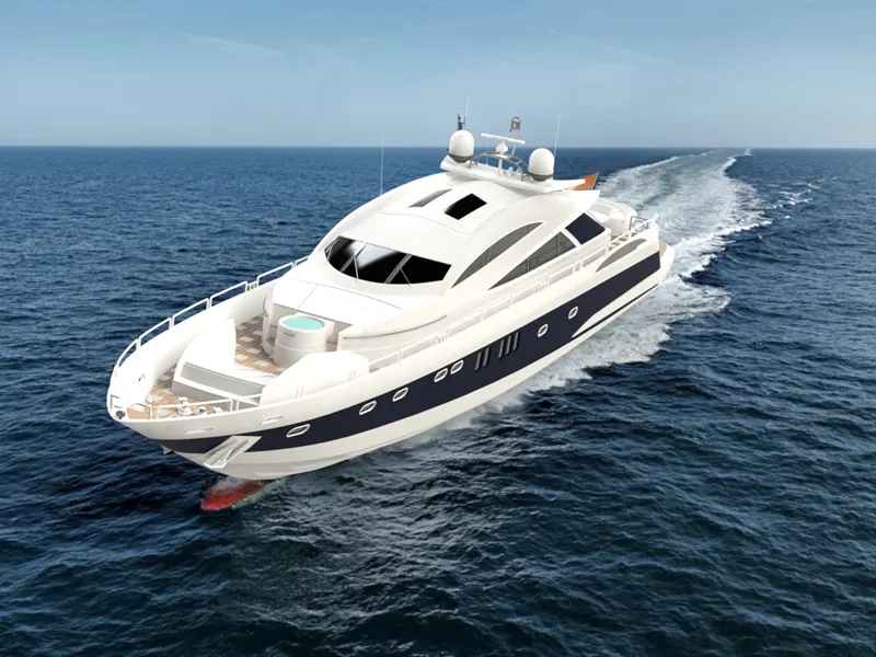
In this our Yacht Assembly rendered to make it more realistic using PV 360 & Solidworks Visualize.
Steps to follow-
- Import - Import assembly once created a new project.
- Appearance - Give appropriate appearances to various parts to make more attractive after rendering.
- Scenes - Use Proper Back Plates/Environment as scenes and drag the assembly at proper location.
- Output - Once done with all setup, a quick render help you out to review final output. Changes the colours by increasing/decreasing various values for better look (if required). Then go for final quallity rendering.
Conclusion:
At the end of Project each and every component of Sunseeker Yacht designed in Part files and all of them Assembled together in Assembly file to get a Complete Design of Yacht. Decals, camera setup & proper scenes are used to give realistic appearance while final rendering.