Assembly of Yacht
MODELLING , ASSEMBLY & RENDERING OF SUNSEEKER PREDATOR YACHT
AIM :
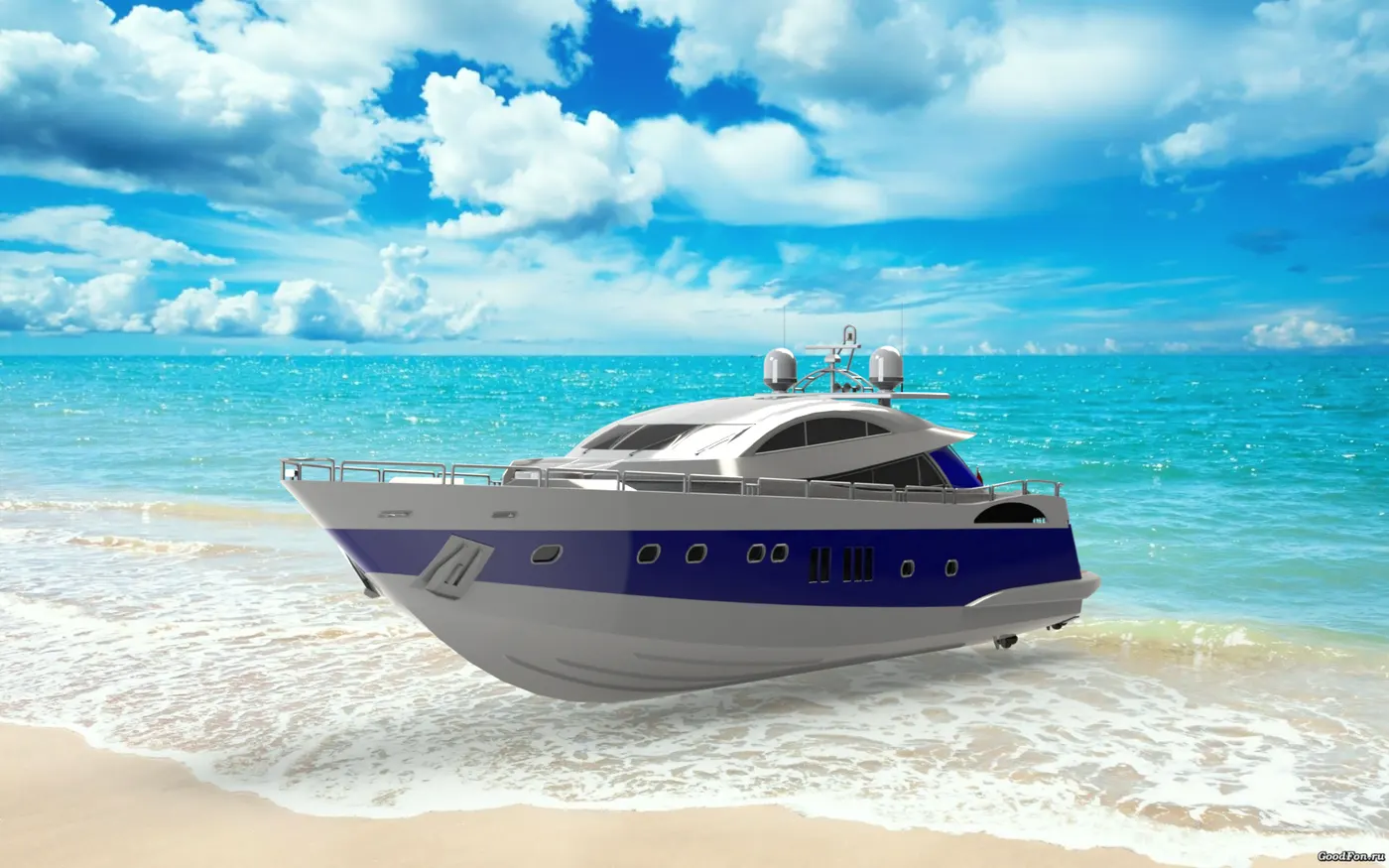
To modelling , assembly & rendering or sunseeker predator yacht in solidworks 2020.
OBJECTIVE :
- To design the different parts of yacht.
- To assemble the parts in part assembly.
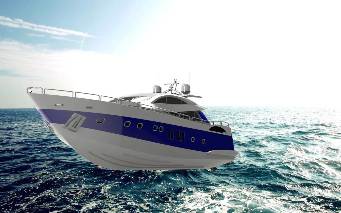
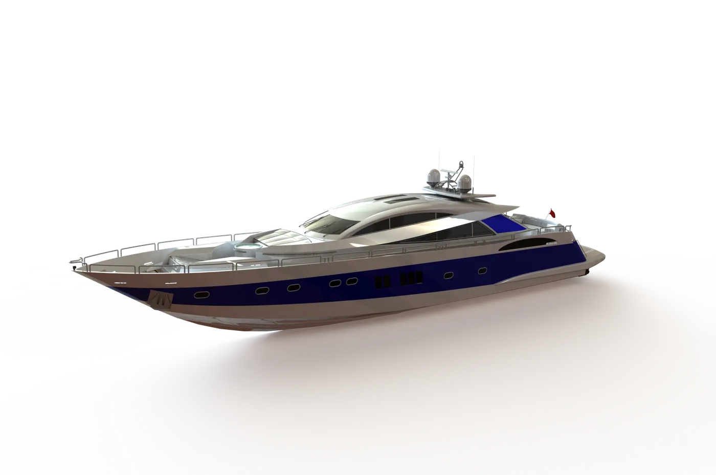
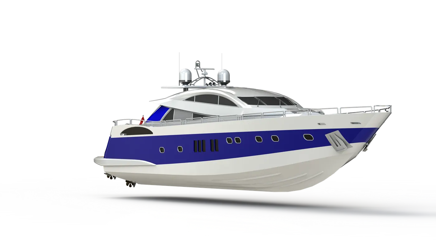
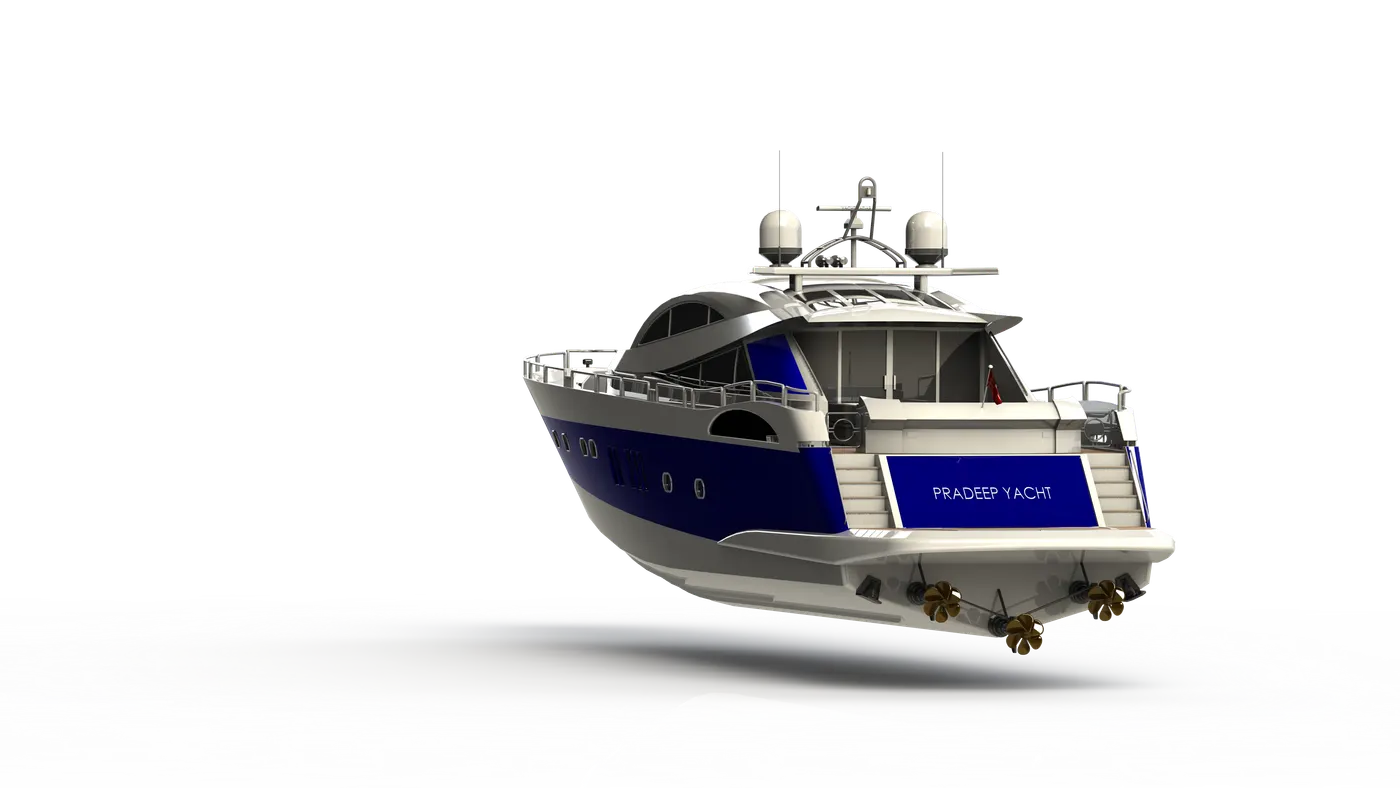
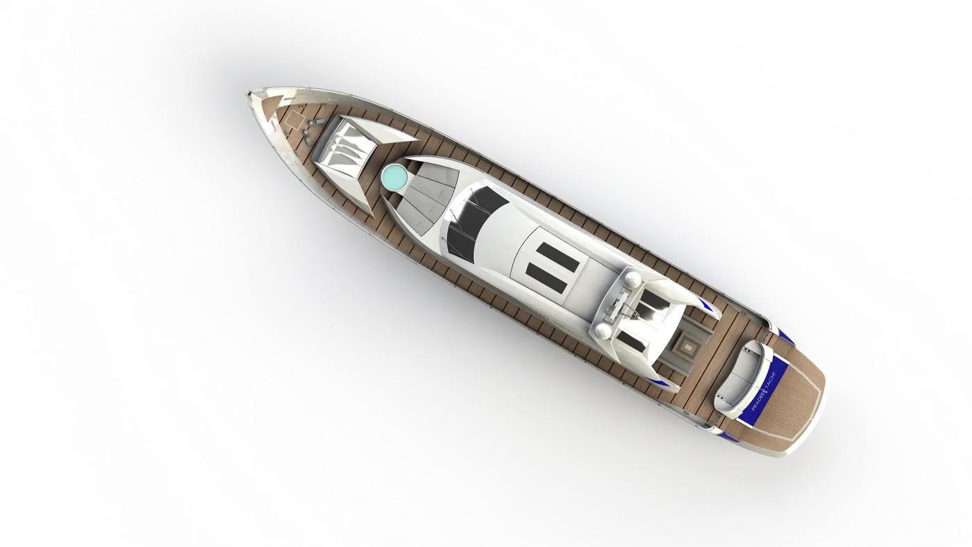
- To create a photorealistic rendering of asembled parts of sunseeker predator yacht in photoview 360.
INTRODUCTION :
A yacht is a sail or power vessel used for pleasure, cruising, or racing. There is no standard definition, so the term applies to such vessels that have a cabin with amenities that accommodate overnight use. To be termed a yacht, as opposed to a boat, such a pleasure vessel is likely to be at least 33 feet (10 m) in length and have been judged to have good aesthetic qualities.
The Commercial Yacht Code classifies yachts 79 ft (24 m) and over as large. Such yachts typically require a hired crew and have higher construction standards. Further classifications for large yachts are: commercial—carrying no more than 12 passengers, private—solely for the pleasure of the owner and guests, or by flag, the country under which it is registered. A super yacht(sometimes megayacht) generally refers to any yacht (sail or power) longer than 131 ft (40 m).
DESIGN METHODOLOGY :
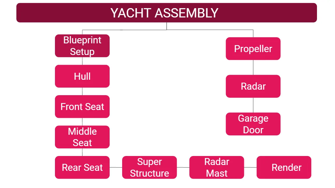
The following parts for yacht,
- Propeller
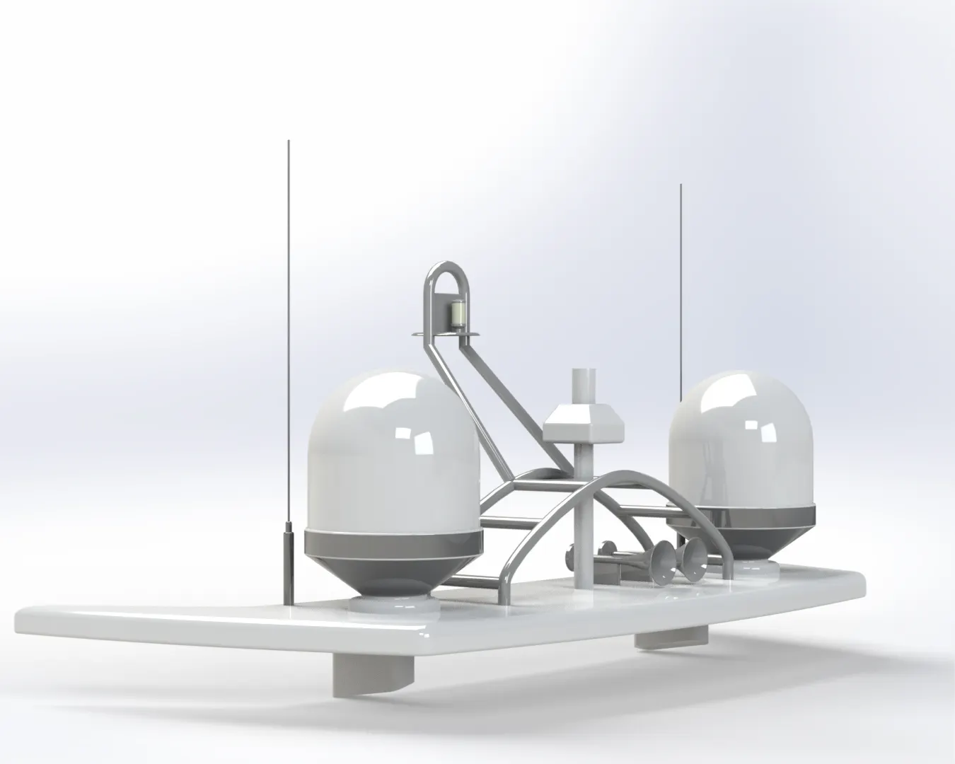
- Radar
- Hull
- Garage Door
- Front seat
- Middle Seat
- Rear Seat
- Super Structure
- Radar Mast
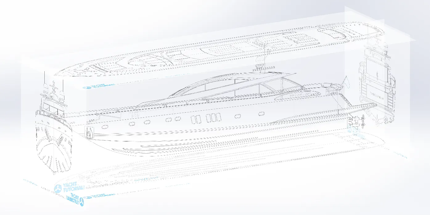
1.) Blueprints Setup :
A blueprint is a guide for making something it's a design or pattern that can be followed.
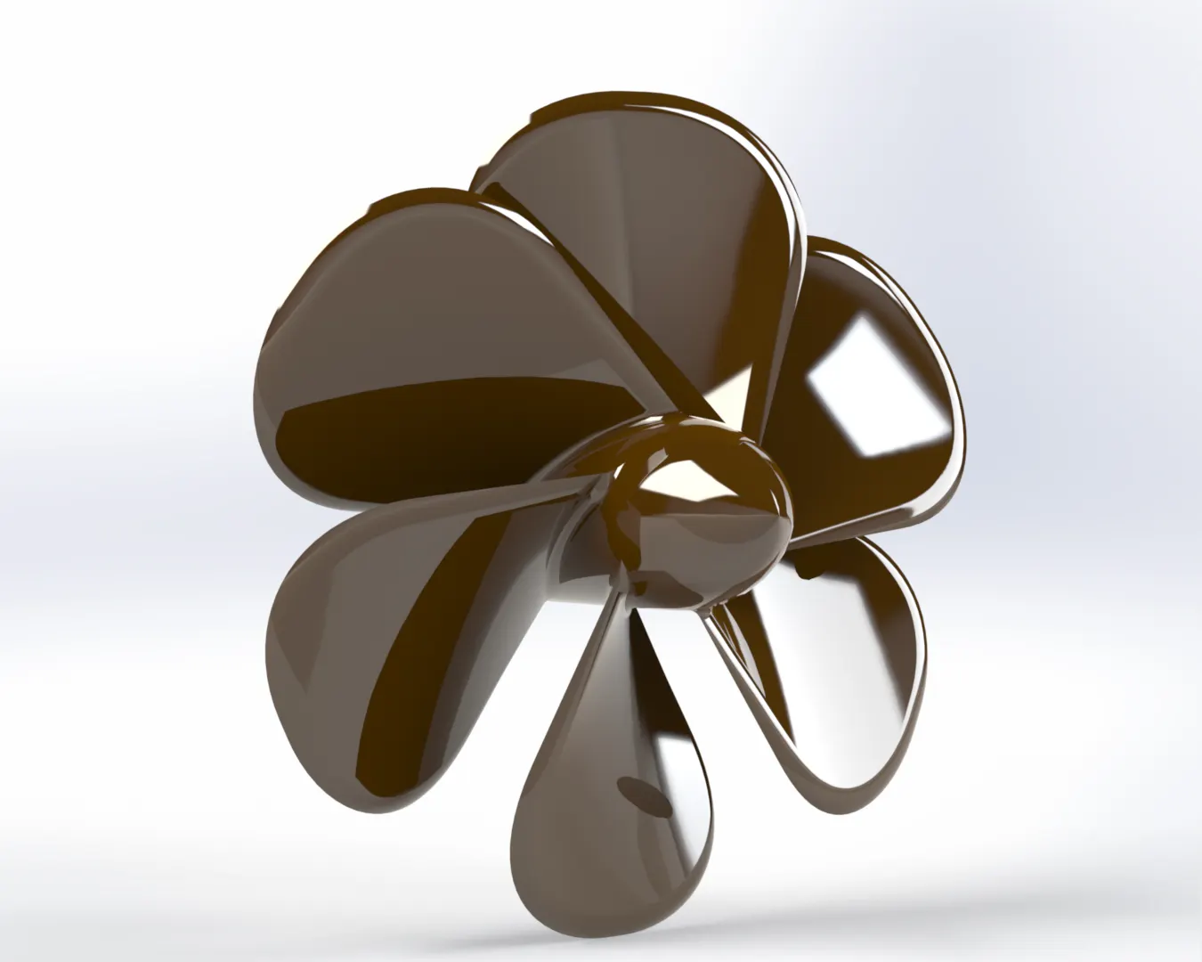
2.) PROPELLER :
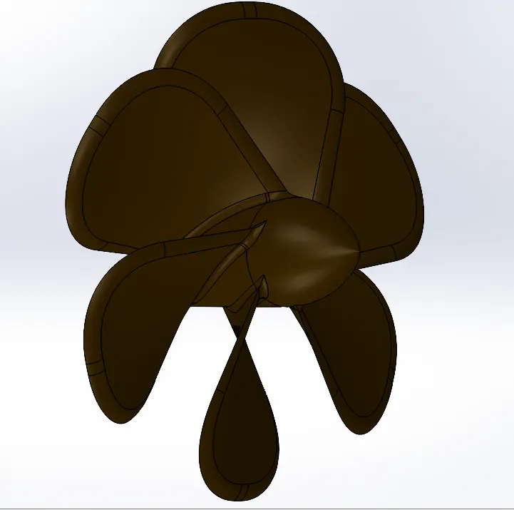
A propeller is a device with a rotating hub and radiating blades that are set at a pitch to form a helical spiral, that, when rotated, performs an action which is similar to Archimedes' screw. It transforms rotational power into linear thrust by acting upon a working fluid, such as water or air.
The rotational motion of the blades is converted into thrust by creating a pressure difference between the two surfaces. A given mass of working fluid is accelerated in one direction and the craft moves in the opposite direction.
Tools used to design this part,
- Sketch - Creates a new sketch or edit the existing sketch, also includes the command of line, circle, arc, slot, spline, etc.
- Revolve - Revolve the sketch or selected sketch contours around the axis to create a solid features.
- Loft - Add material between 2 or more profiles to create a solid features.
- Cut Extrude - Cut a solid model by extruding a sketched profile in 1 or 2 directions.
- Circular Pattern - Pattern features, faces & bodies around the selected axis.
- Fillet - Creates a rounded internal or external face along 1 or more edge on a solid or surface feature.
3.) RADAR :
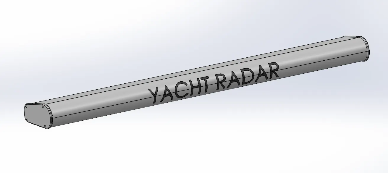
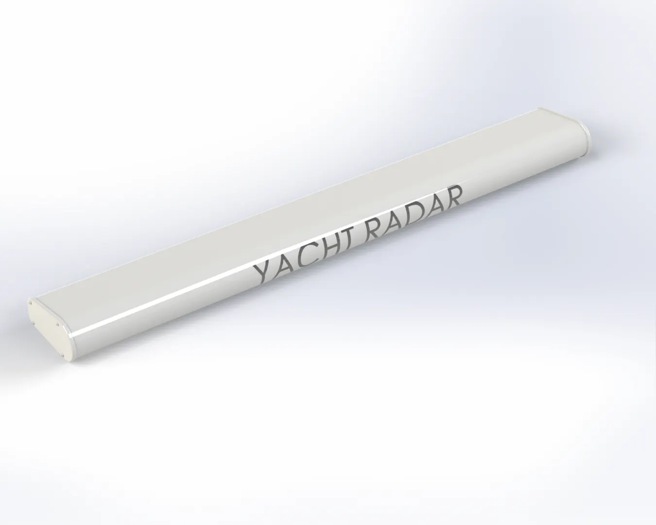
Radar is a detection system that uses radio waves to determine the range, angle, or velocity of objects. It can be used to detect aircraft, ships, spacecraft, guided missiles, motor vehicle, weather formation, and terrain. A radar system consists of a transmitter producing electromagnetic waves in the radio or microwaves domain, a transmitting antenna, a receiving antenna (often the same antenna is used for transmitting and receiving) and a receiver and processor to determine properties of the objects.
Tools used to design this part,
- Boss Extrude - Extrudes a sketch or selected sketch contours in 1 or 2 directions to create a solid features.
- Cut Extrude - Cut a solid model by extruding a sketched profile in 1 or 2 directions.
- Sketch Pattern - Pattern features, faces & bodies based on sketch points.
- Split Line - Projects the sketch to curved or planar face & creating multiple seperate faces.
- Mirror - Mirrors features, faces & bodies about a plane or a planar face.
- Fillet - Creates a rounded internal or external face along 1 or more edge on a solid or surface feature.
4.) HULL :
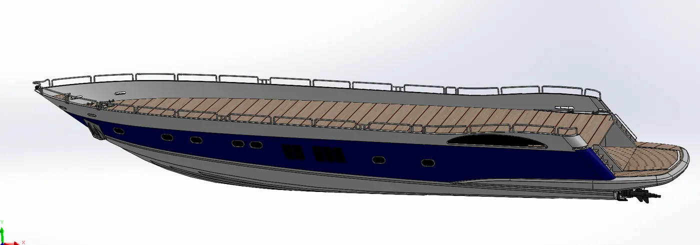
A hull is the watertight body of a ship or boat. The hull may open at the top (such as a dinghy), or it may be fully or partially covered with a deck. Atop the deck may be a deckhouse and other superstructures, such as a funnel, derrick, or mast. The line where the hull meets the water surface is called the waterline.
There is a wide variety of hull types that are chosen for suitability for different usages, the hull shape being dependent upon the needs of the design. Shapes range from a nearly perfect box in the case of scow barges, to a needle-sharp surface of revolution in the case of a racing multihull sailboat. The shape is chosen to strike a balance between cost, hydrostatic considerations (accommodation, load carrying and stability), hydrodynamics (speed, power requirements, and motion and behavior in a seaway) and special considerations for the ship's role, such as the rounded bow of an ice breaker or the flat bottom of a landing craft.
Tools used to design this part,
- Sketch - Creates a new sketch or edit the existing sketch, also includes the command of line, circle, arc, slot, spline, etc.
- Project Curve - projects the sketched curves onto a face or curve.
- Surface Loft - Creates a loafted surface between 2 or more profiles or sketches.
- Surface Trim - Trims where the surface intract with another surface.
- Surface Extrude - Extrudes a sketch or selected sketch contours in 1 or 2 directions to create a surface features.
- Surface Knit - Combine 2 or more adjacent & non-intersecting surfaces into a single surface body.
- Surface Fill - Patches the surface within a boundary defined by edges, sketch or curves.
- Shell - Hollows out a part, leaving opening the faces you select,And creating thin-walled features on the reamining faces.
- Cut Extrude - Cut a solid model by extruding a sketched profile in 1 or 2 directions.
- Fillet - Creates a rounded internal or external face along 1 or more edge on a solid or surface feature.
- Chamfer - Creates a bewel features along the edge, a chain of tangent edges or the vertex.
- Sweep - sweeps a closed profile along an open or closed path to create a solid or surface features.
- Boss Extrude - Extrudes a sketch or selected sketch contours in 1 or 2 directions to create a solid features.
- Revolve - Revolve the sketch or selected sketch contours around the axis to create a solid features.
- Dome - Add 1 or more domes to selected planar or non-planar faces.
- Helix/Spiral - Plane, planar face or the edge on which the sketch a circle to define the helix cross section.
- Linear Pattern - Pattern features, faces & bodies in 1 or 2 linear directions.
- Add/Delete Face - Add/Delete solid bodies to create surfaces.
- Thin Extrude - Extrudes a sketch or selected sketch contours in 1 or 2 directions to create a thin solid features.
- Thin cut Extrude - Cut a solid model by extruding thin a sketched profile in 1 or 2 directions.
- Split - Creates multiple bodies from single body.
- Split Line - Projects the sketch to curved or planar face & creating multiple seperate faces.
- Offset Surface - Creates the surface on the faces.
- Mirror - Mirrors features, faces & bodies about a plane or a planar face.
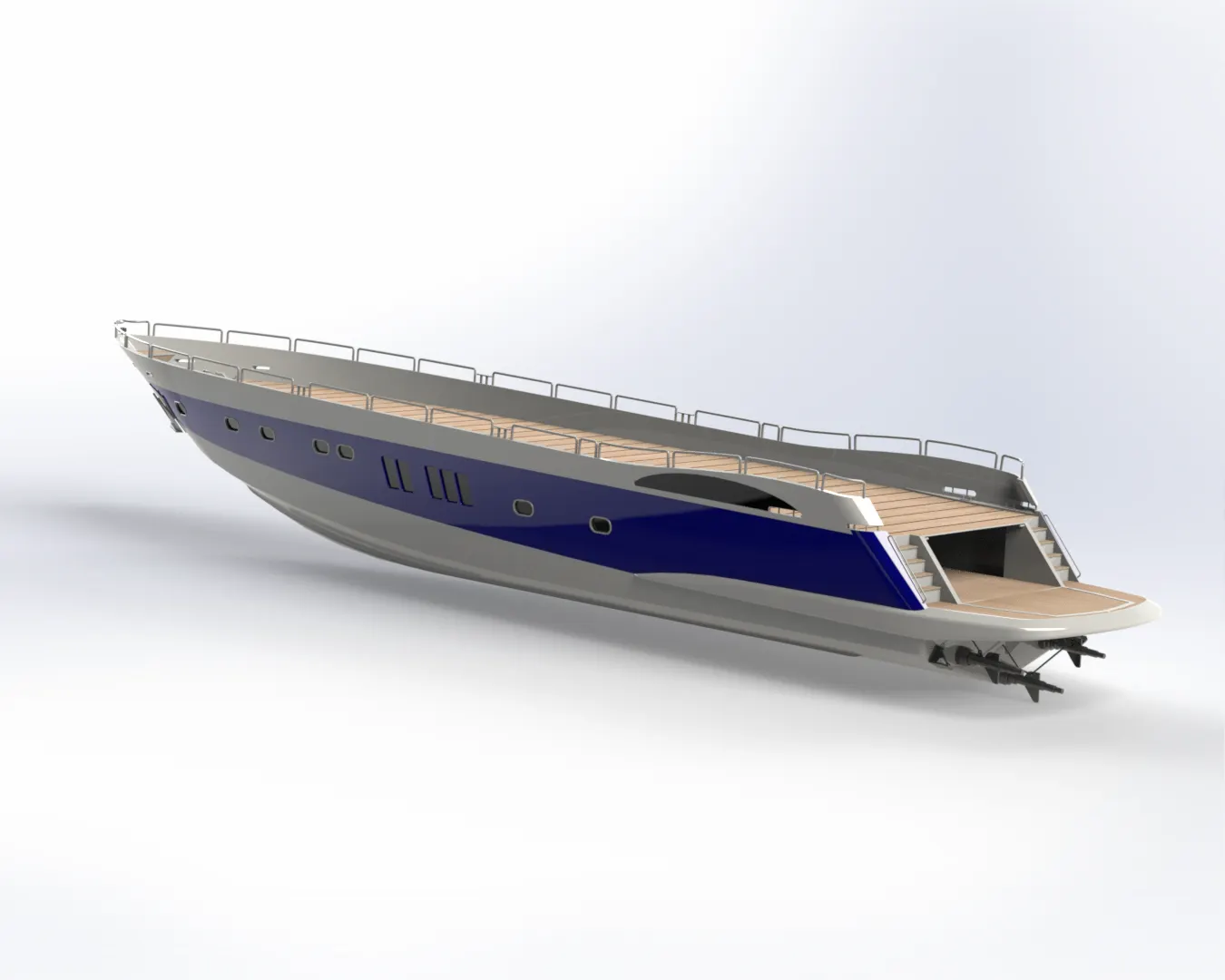
5.) GARAGE DOOR :
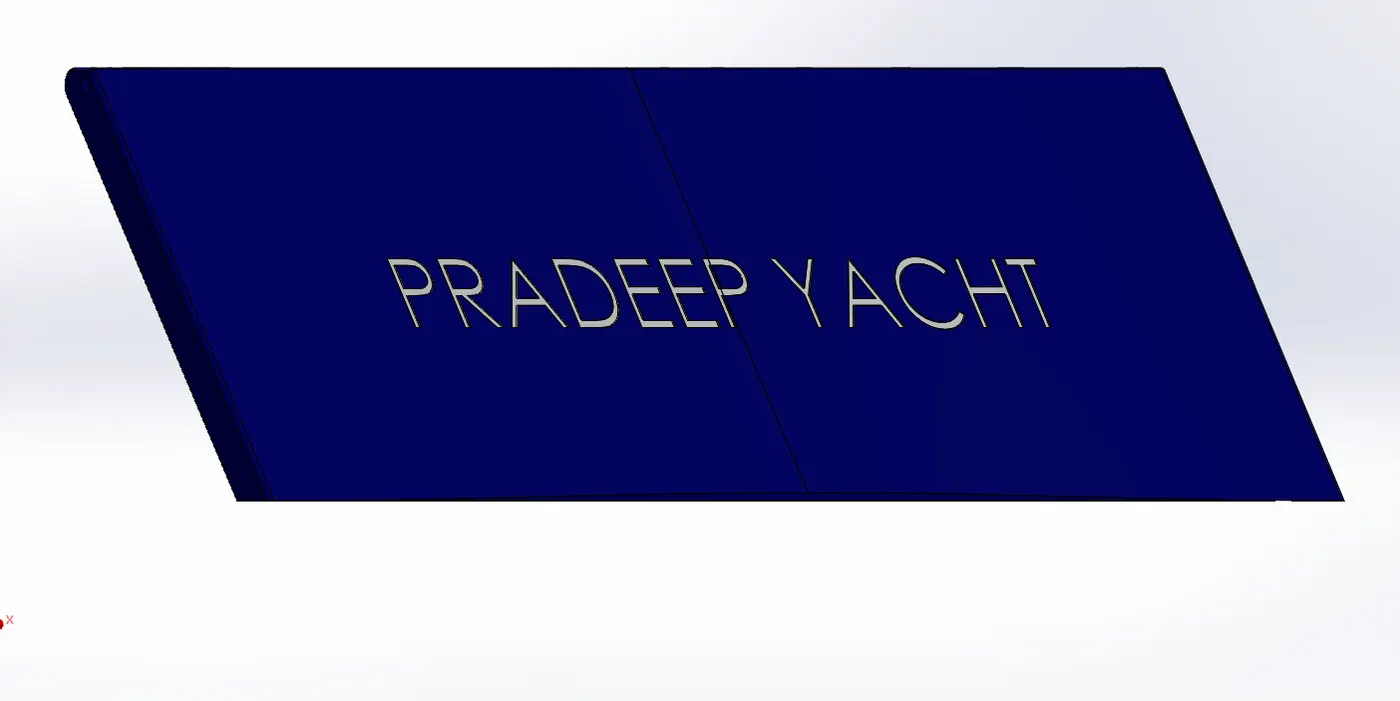
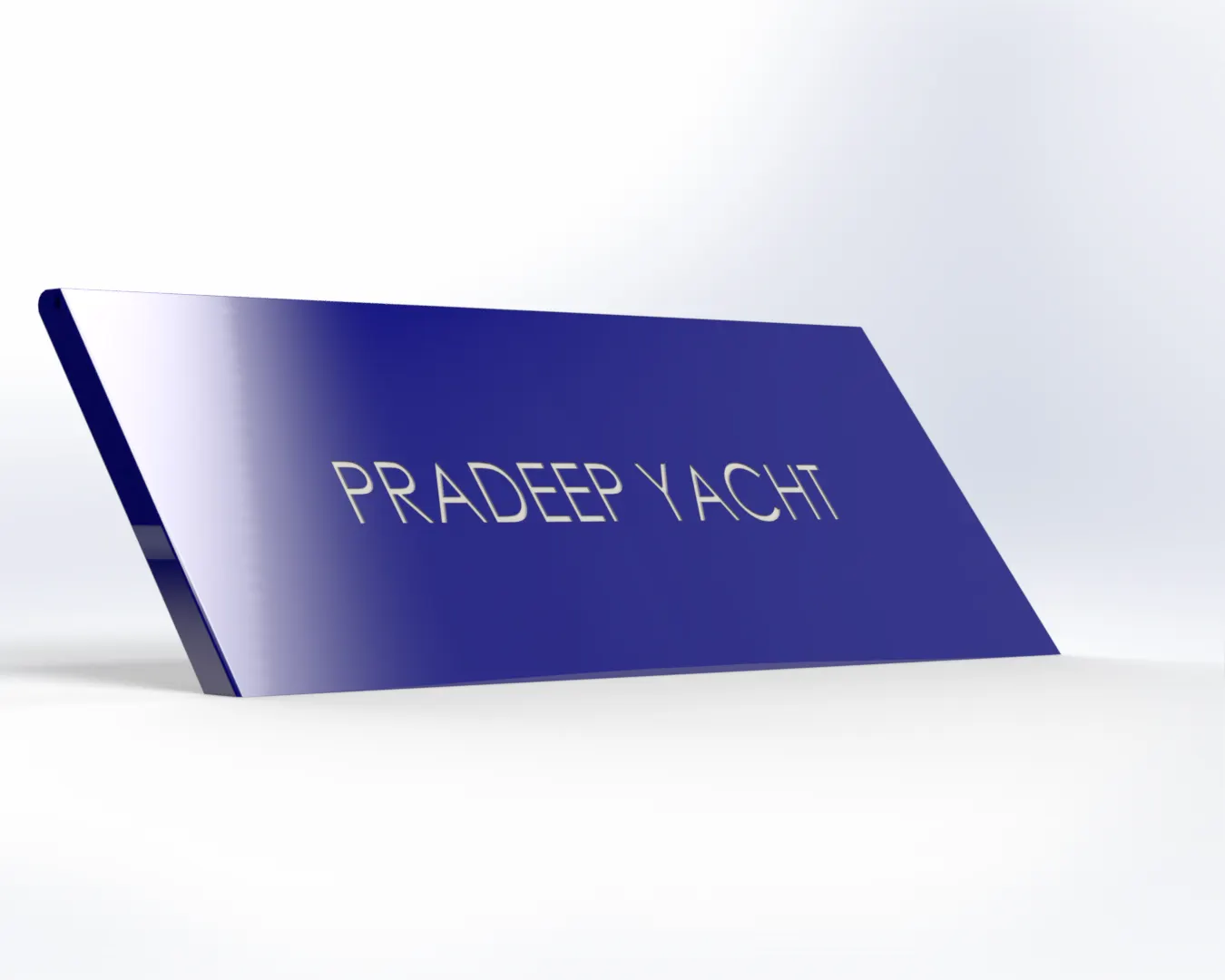
A garage door is a large door on a garage that opens either manually or by an electric motor. Garage doors are frequently large enough to accommodate automobiles and other vehicles. Small garage doors may be made in a single panel that tilts up and back across the garage ceiling. Larger doors are usually made in several jointed panels that roll up on tracks across the garage ceiling, or into a roll above the doorway. The operating mechanism is spring-loaded or counterbalanced to offset the weight of the door and reduce human or motor effort required to operate the door.
Tools used to design this part,
- Cut Extrude - Cut a solid model by extruding a sketched profile in 1 or 2 directions.
- Shell - Hollows out a part, leaving opening the faces you select,And creating thin-walled features on the reamining faces.
- Mirror - Mirrors features, faces & bodies about a plane or a planar face.
- Fillet - Creates a rounded internal or external face along 1 or more edge on a solid or surface feature.
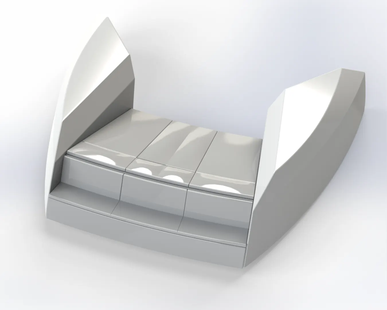
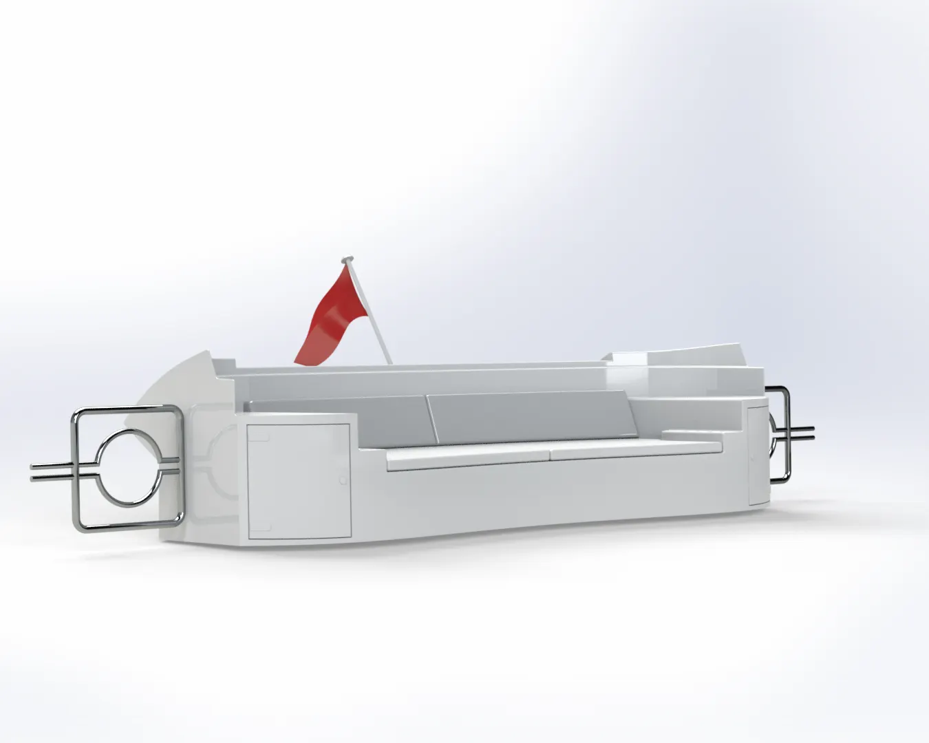
6.) Front Seat :
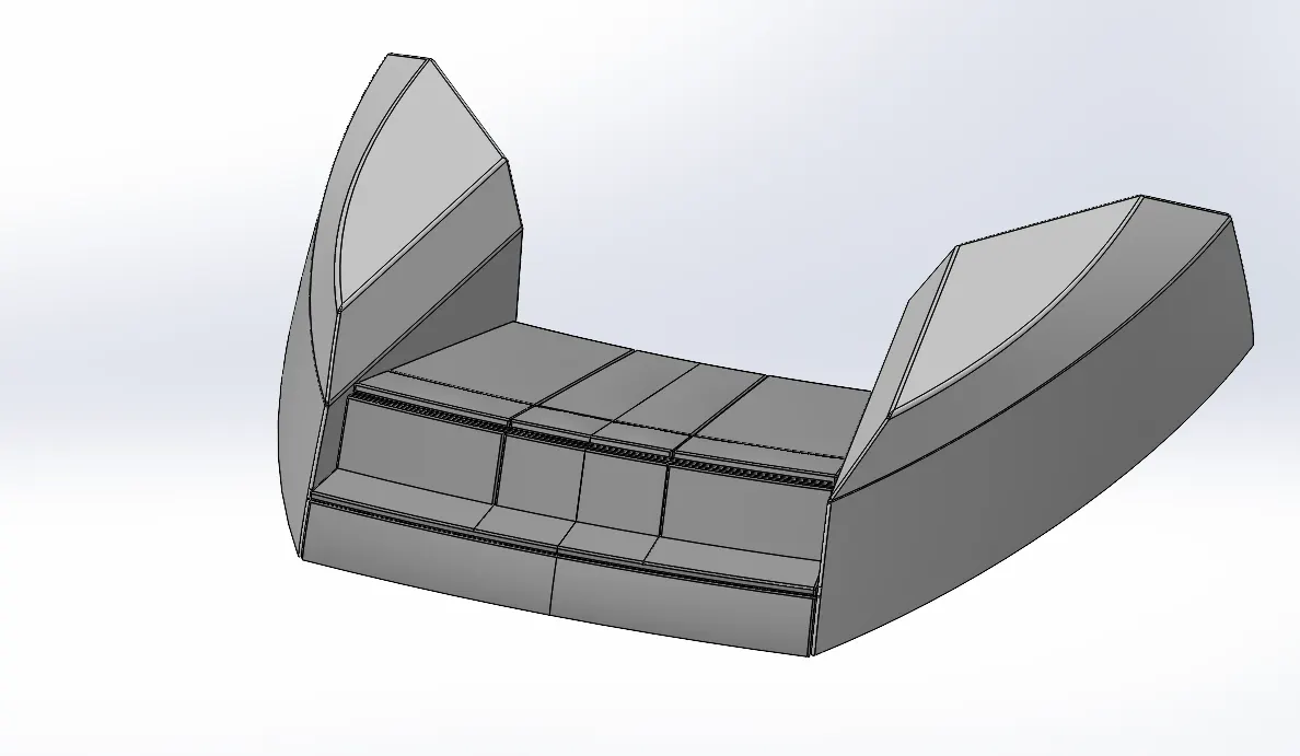
The seat creates white lines that connect it to whatever ability block it is bound to. While it is useful for setting up controls, it can often throw off a boat's aesthetic looks.
Tools used to design this part,
- Surface Sweep -sweeps a closed profile along an open or closed path to create a or surface features.
- Surface Extrude - Extrudes a sketch or selected sketch contours in 1 or 2 directions to create a surface features.
- Surface Fill - Patches the surface within a boundary defined by edges, sketch or curves.
- Surface Trim -Trims where the surface intract with another surface.
- Surface Loft - Creates a loafted surface between 2 or more profiles or sketches.
- Surface Knit - Combine 2 or more adjacent & non-intersecting surfaces into a single surface body.
- Revolve - Revolve the sketch or selected sketch contours around the axis to create a solid features.
- Cut Extrude - Cut a solid model by extruding a sketched profile in 1 or 2 directions.
- Cut Thin Extrude - Cut a solid model by extruding thin a sketched profile in 1 or 2 directions.
- Chamfer - Creates a bewel features along the edge, a chain of tangent edges or the vertex.
- Fillet - Creates a rounded internal or external face along 1 or more edge on a solid or surface feature.
- Mirror - Mirrors features, faces & bodies about a plane or a planar face.
- Dome - Add 1 or more domes to selected planar or non-planar faces.
7.) MIDDLE SEAT :
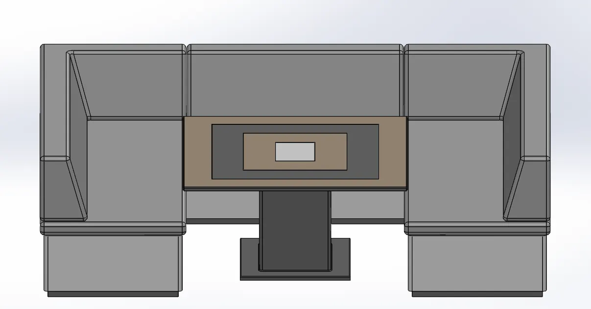
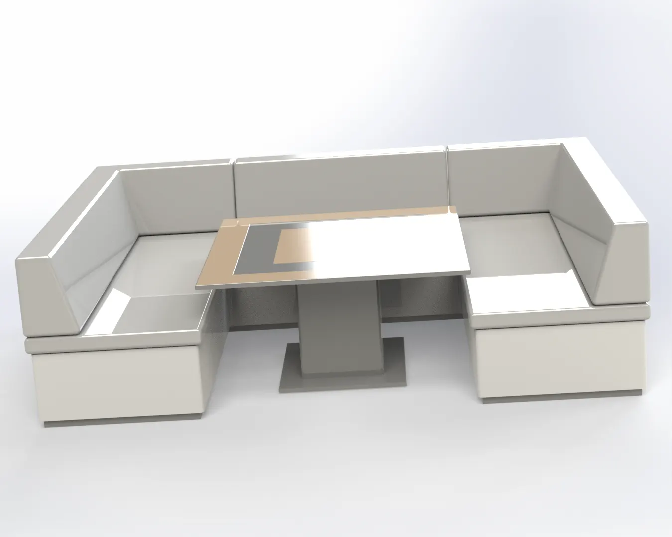
The seat creates white lines that connect it to whatever ability block it is bound to. While it is useful for setting up controls, it can often throw off a boat's aesthetic looks.
Tools used to design this part,
- Boss Extrude - Extrudes a sketch or selected sketch contours in 1 or 2 directions to create a solid features.
- Mirror - Mirrors features, faces & bodies about a plane or a planar face.
- Cut Extrude - Cut a solid model by extruding a sketched profile in 1 or 2 directions.
- Chamfer - Creates a bewel features along the edge, a chain of tangent edges or the vertex.
- Fillet - Creates a rounded internal or external face along 1 or more edge on a solid or surface feature.
8.) REAR SEAT :
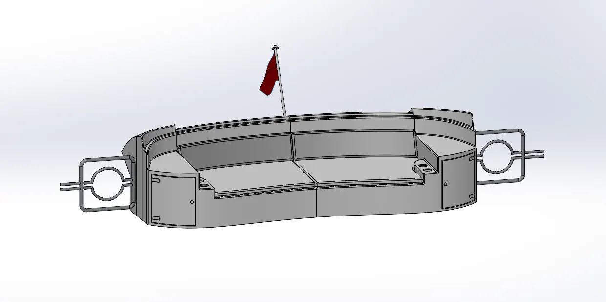
The seat creates white lines that connect it to whatever ability block it is bound to. While it is useful for setting up controls, it can often throw off a boat's aesthetic looks.
Tools used to design this part,
- Surface Sweep - sweeps a closed profile along an open or closed path to create a or surface features.
- Surface Offset - Creates the surface on the faces.
- Surface Trim - Trims where the surface intract with another surface.
- Ruled Surface - Insert ruled surface in a specified direction from edges.
- Surface Knit - Combine 2 or more adjacent & non-intersecting surfaces into a single surface body.
- Surface Extend - Extend one or more edges or faces on surface.
- Surface Extrude - Extrudes a sketch or selected sketch contours in 1 or 2 directions to create a surface features.
- Surface Loft - Creates a loafted surface between 2 or more profiles or sketches.
- Boss Extrude - Extrudes a sketch or selected sketch contours in 1 or 2 directions to create a solid features.
- Cut extrude - Cut a solid model by extruding a sketched profile in 1 or 2 directions.
- Chamfer - Creates a bewel features along the edge, a chain of tangent edges or the vertex.
- Boss Sweep - sweeps a closed profile along an open or closed path to create a or solid features.
- Mirror - Mirrors features, faces & bodies about a plane or a planar face.
- Revolve - Revolve the sketch or selected sketch contours around the axis to create a solid features.
- Fillet - Creates a rounded internal or external face along 1 or more edge on a solid or surface feature.
9.) SUPERSTRUCTURE :
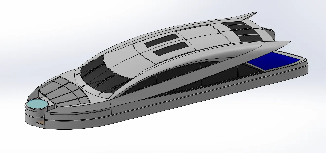
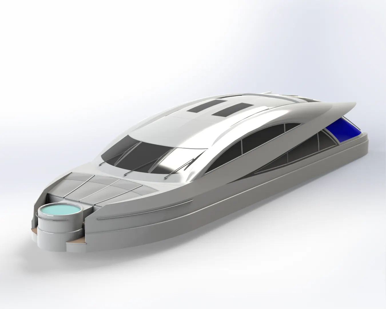
A superstructure is an upward extension of an existing structure above a baseline. This term is applied to various kinds of physical structures such as buildings, bridges, or ships having the degree of freedom zero (in the terms of theory of machines).
Superstructure consists of the parts of the ship or a boat, including sailboats, fishing boats, passenger ships, and submarines, that project above her main deck. This does not usually include its masts or any armament turrets.
Tools used to design this part,
- Surface Sweep - sweeps a closed profile along an open or closed path to create a or surface features.
- Surface Knit - Combine 2 or more adjacent & non-intersecting surfaces into a single surface body.
- Project Curve - Projects the sketched curves onto a face or curve.
- Surface loft - Creates a loafted surface between 2 or more profiles or sketches.
- Surface Fill - Patches the surface within a boundary defined by edges, sketch or curves.
- Surface Extrude - Extrudes a sketch or selected sketch contours in 1 or 2 directions to create a surface features.
- Surface Trim - Trims where the surface intract with another surface.
- Ruled Surface - Insert ruled surface in a specified direction from edges.
- Surface Extend - Extend one or more edges or faces on surface.
- Fillet - Creates a rounded internal or external face along 1 or more edge on a solid or surface feature.
- Cut-Extrude - Cut a solid model by extruding a sketched profile in 1 or 2 directions.
- Face Delete - Add/Delete solid bodies to create surfaces.
- Boss Extrude - Extrudes a sketch or selected sketch contours in 1 or 2 directions to create a solid features.
- Surface Offset - Creates the surface on the faces.
- Thickness - Creates a solid surface by thickening the one or more adjecent surface.
- Dome - Add 1 or more domes to selected planar or non-planar faces.
- Boss Sweep - Sweeps a closed profile along an open or closed path to create a or solid features.
- Extrude Thin - Extrudes a sketch or selected sketch contours in 1 or 2 directions to create a thin solid features.
- Split Line - Projects the sketch to curved or planar face & creating multiple seperate faces.
- Mirror - Mirrors features, faces & bodies about a plane or a planar face.
- Chamfer - Creates a bewel features along the edge, a chain of tangent edges or the vertex.
10.) RADAR MAST :
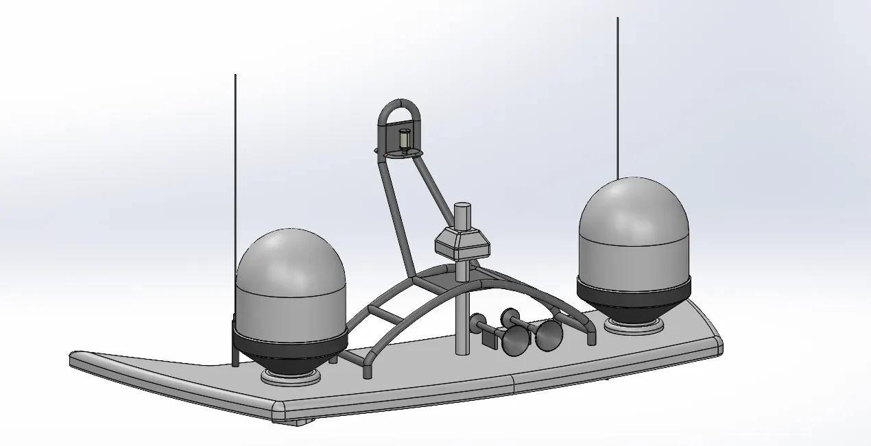
Radar is a detection system that uses radio waves to determine the range, angle, or velocity of objects. It can be used to detect aircraft, ships, spacecraft, guided missiles, motor vehicle, weather formation, and terrain. A radar system consists of a transmitter producing electromagnetic waves in the radio or microwaves domain, a transmitting antenna, a receiving antenna (often the same antenna is used for transmitting and receiving) and a receiver and processor to determine properties of the objects.
The information provided by radar includes the bearing and range (and therefore position) of the object from the radar scanner. It is thus used in many different fields where the need for such positioning is crucial. The first use of radar was for military purposes: to locate air, ground and sea targets. This evolved in the civilian field into applications for aircraft, ships, and automobiles.
Tools used to design this part,
- Boss Extrude - Extrudes a sketch or selected sketch contours in 1 or 2 directions to create a solid features.
- Revolve - Revolve the sketch or selected sketch contours around the axis to create a solid features.
- Fillet - Creates a rounded internal or external face along 1 or more edge on a solid or surface feature.
- Boss Sweep - Sweeps a closed profile along an open or closed path to create a or solid features.
- Mirror - Mirrors features, faces & bodies about a plane or a planar face.
- Project Curve -projects the sketched curves onto a face or curve.
- Chamfer - Creates a bewel features along the edge, a chain of tangent edges or the vertex.
- Mirror - Mirrors features, faces & bodies about a plane or a planar face.
Assembly of Sunseeker Predator Yacht :
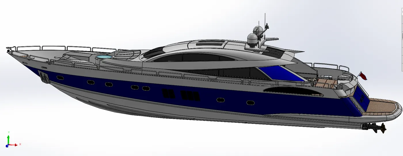
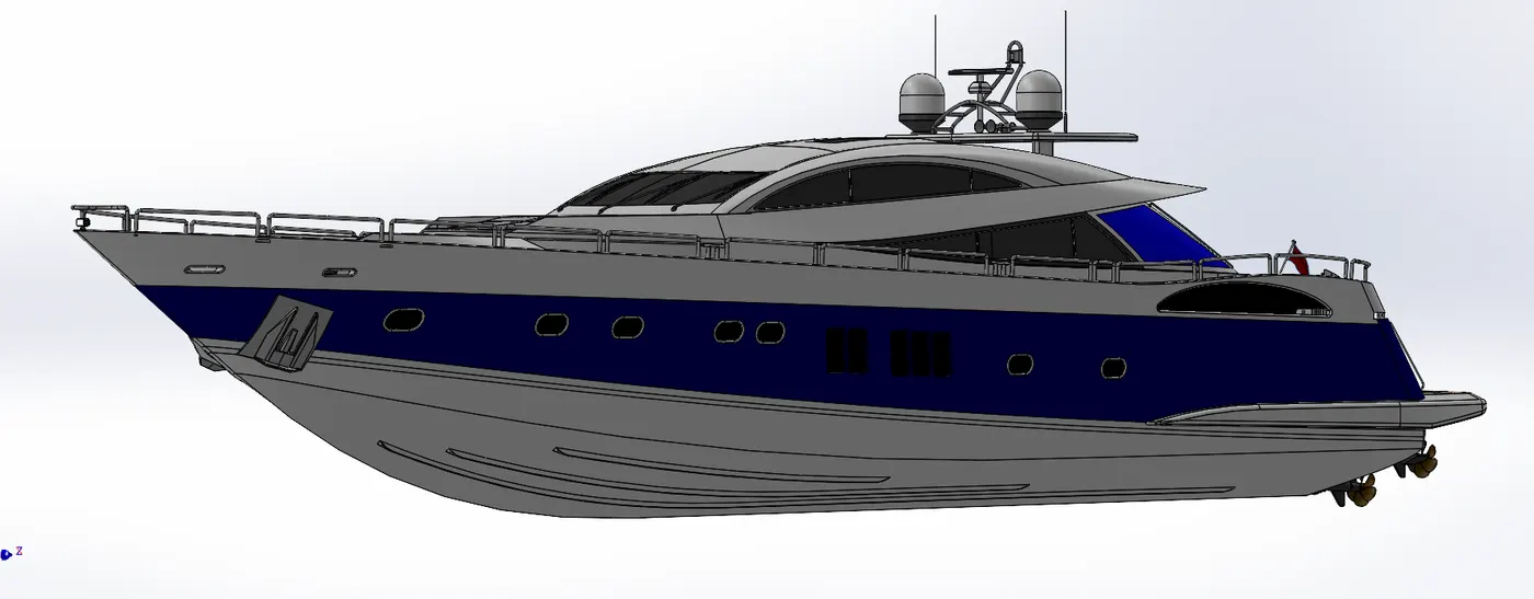
All the modeled parts are inserted in the assembly section by using the command insert components (Add an existing parts to the assembly). the parts are assembled as one with the help of planes , mates.
Mates :
Create geometric relation between the component, To define the allowable direction of linear or rotational motion to the parts.
Photorealistic Rendering of Sunseeker Predator Yacht Using SolidWorks Visualise 2020 :
- Rendering is the process of converting 3D models into an realistics images and its done in solidworks photoview 360 or solidworks visualise.
- In the rendering process we can edit the background & environment of an image.
- Inside the render tools we can add or edit the scenes, appearance & decals.
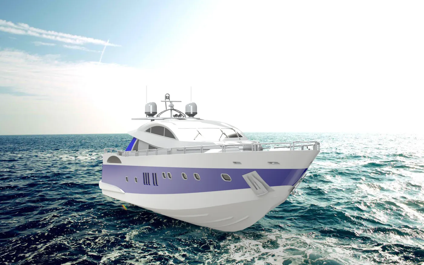
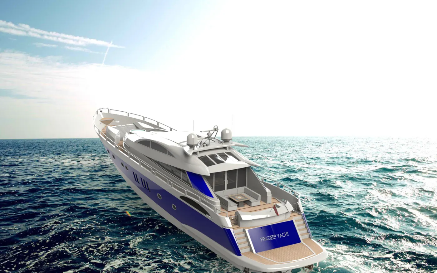
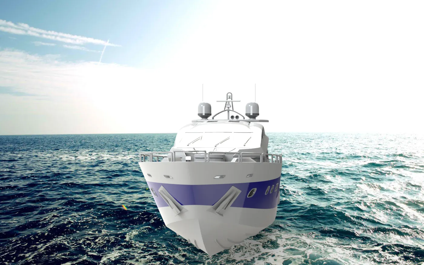
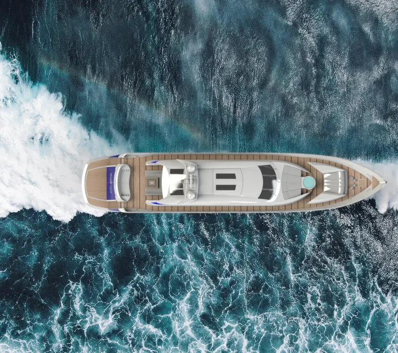
Photorealistic of Sunseeker Predator Yacht in Photoview 360 :
LINK FOR THE YACHT PARTS IN SOLIDWORK : Pradeep's_Sunseeker_Predator_Yacht
CONCLUSION :
Thus to modelling all the parts inside of sunseeker predator yacht and assembled & rendered together sucessfully in solidworks 2020.