Analytical study of DC motor and it's speed for the Eelectric vehicle using simulink.
Aim:
To study the characteristics of the traction motor in the vehicle.
Objectives:
To study the power converter circuits used in the elctric vehicles and hybrid electric vehicles.To study the vehicle's speed-torque characteristics for the given equation.To develope the mathematical model of the DC motor for the given equation.To study and explain the Induction vs. DC brushless motors.
Introduction:
What is a Power Converter?
A power converter is an electrical circuit that changes the electric energy from one form into the desired form optimized for the specific load. A converter may do one or more functions and give an output that differs from the input. It is used to increase or decrease the magnitude of the input voltage, invert polarity, or produce several output voltages of either the same polarity with the input, different polarity, or mixed polarities such as in the computer power supply unit.
What is duty ratio?
Duty cycle is the ratio of time a load or circuit is ON compared to the time the load or circuit is OFF.
Duty cycle, sometimes called "duty factor," is expressed as a percentage of ON time. A 60% duty cycle is a signal that is ON 60% of the time and OFF the other 40%.
Figure01: Multimeter showing the reading and the value of the duty cycle with the help of wave diagram and circuit diagram.
Many loads are rapidly cycled on and off by a fast-acting electronic switch which accurately controls the output power of the load. Load operation—such as lamp brightness, heating element outputs and the magnetic strength of a coil—can be duty cycle-controlled by ON and OFF time periods or cycles per second.
Duty Cycle:
If the valve is pulsed ON at variable durations (called pulse-width modulation), the duty cycle varies. If it is pulsed ON for 0.05 seconds in a 0.1-second cycle, the fuel injector duty cycle equals 50%. If it pulsed ON for 0.09 seconds of that same 0.1-second cycle, the fuel injector duty cycle equals 90%.
Example:
In an automotive electronic fuel injection system, voltage pulses supplied to the fuel injector valve solenoid control the fuel injector valve at a fixed rate of 10 cycles per second, or 10 Hz.
Pulse width modulation allows fuel supplied to the engine to be precisely controlled electronically. The voltage average for each duty cycle is determined by the amount of pulse ON time.
Duty cycled solenoids use a variable duty cycle signal to vary flow or adjust pressure. The longer a solenoid remains open, the more flow and less pressure develops. These solenoids are either feed-controlled or ground-controlled.
What is pulse width?
Pulse width is a measure of the actual ON time, measured in milliseconds. The OFF time does not affect signal pulse width. The only value being measured is how long the signal is ON (ground-controlled).
Problem Statement:
Which types of power converter circuits are employed in electric and hybrid electric vehicle?-
An Electric Vehicle's powertrain with 72V battery pack in shown in the diagram below. The duty ratio for acceleration operation is 'd1' and for the braking operation the duty ratio is 'd2'.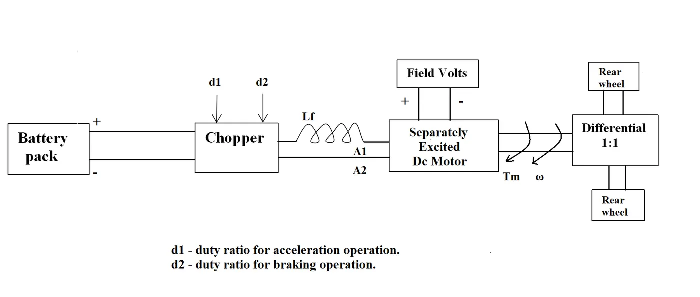
The other parameters of the electric vehicle is given below,Motor and Controller Parameters:Rated Armature voltage= 72 VRated armature current= 400 ARa= 0.5Ω, KΦ= 0.7 Volt secondChopper Switching frequency= 400 HzThe vehicle speed-torque characteristics are given by the below equation
What is EV steady state speed if duty cycle is 70%? -
Develop a mathematical model of a DC Motor for the below equation using Simulink.ω">ω= V/Kϕ">ϕ -Ra/Kϕ">ϕ^2 .T -
Refer to the blog on below topic:Induction Versus DC brushless motors by Wally Rippel, TeslaExplain in brief about author’s perspective.
Solution:
I.
Following are the types of power converters used in the elctric vehicles and Hybrid-electric vehicles:
01. AC to DC Power converter circuit:
To charge the battery of the vehicle we need to convert the AC current into DC current which justifies the need of AC to DC power converter to charge the battery of the vehicle.
02. DC to DC Power converter circuit:
To perform the various operations inside the vehicle such as turning ON infotainment display, headlights, changing modes of the vehicle, changing type of drives and adjusting the temperatures inside the vehicles requires the change in magnitude of the power which in turn requires the change in magnitude of the DC current from the battery thus DC to Dc power converter circuit is used so that such operations can be performed efficiently.
03. DC to AC Power converter circuit:
To convert the DC of the battery into AC to feed the motor which in turn provides power for rotation of wheels.
II.
We know that;
`omega=(V/(k.phi))-(R/(k.phi)^2).T`
...equation (01)
Here we need find the value of speed of motor (RPM) `omega`.
Therefore we will substitute the values of Battery voltage (`V`), Motor constant (`k.phi`), Resistance (`R`) and Torque of the motor (`T`) as per given data in equation 01.
Therefore,
`omega=(72/0.7)-(0.5/(0.7)^2).T`
`omega=102.85-1.02T`
`omega+1.02T=102.85`
Therefore,
`T=((102.85-omega)/1.02)`
...equation (a)
We also have,
`T=24.7+(0.0051)*omega^2`
...equation (02)
Therefore, equating equatiions (a) and (02) we get,
`((102.85-omega)/1.02)= 24.7 + ( 0.0051 ) ⋅ omega^2`
`(102.85-omega)=1.02(24.7+(0.0051)*omega^2)`
`(102.85-omega)=25.194+0.00520*omega^2`
`102.85-25.194=0.00520*omega^2+omega`
`77.66=0.00520*omega^2+omega`
Therefore,
`0.00520*omega^2+omega-77.66=00`
...equation (03)
By solving above quadratic equation we get,
`omega=1130`
RPM
Therefore,
`omega=((2pi*1130)/60)`
m/s
`omega=118.27`
m/s
Considering the duty cycle during acceleration d2 as 70%
Steady speed of motor is given by'
`omega=0.7*118.27`
Therefore.
`omega=82.79`
m/s
`omega=(82.79*1000)/3600`
km/hr
`omega=23`
km/hr
Therefore speed of an EV is 23 km/hr.
III.
Here we will model the DC motor in the simulink for the motor's speed-trorque equation given below:
`omega=(V/(k.phi))-(R/(k.phi)^2).T`
Simulink model for the equation of speed of DC motor.
Let's assume that the values of the current and voltage continuously varying with the requirements of the vehicle therefore a varying signal is taken as a input for both current and voltage.
Motor constant is assumes as 0.79.
Althought the torque varies with the requirements of the vehicle but in this model we are considering it as constant 1 and study the behaviour of the speed of the motor.
The model consists of the subsystem termed as "DC motor" which is actually the simulink model of the equation of the speed of the motor.
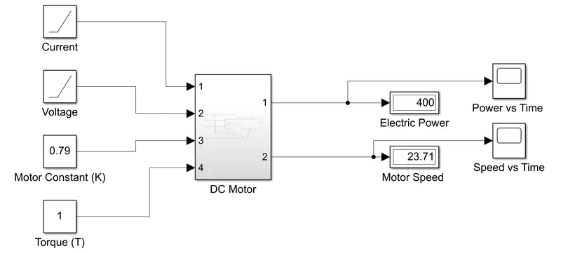
Figure02: Complete simulink model of the equation of the speed of the motor.
Now let's study the subsystem model "DC motor" in detail.
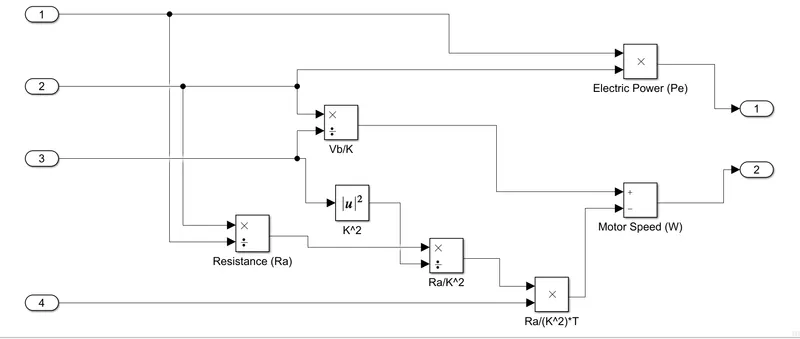
Figure03: Subsystem "DC motor" model in the simulink for it's equation of speed of motor.
Four inputs are current, voltage, motor constant and torque are taken.
Firstly current is taken for the calculation of the electric power (Pe) and secondly to calculate resistance (Ra) of the circuit.
Resistance is calculated by using the relation V=IR.
where,
V = Battery voltage.
I = Current in the circuit.
R = Resistance of the circuit.
Now the voltage is taken for the calculation of the resistance (Ra).
Further the motor constant and same value of the voltage is used to find the value of "Vb/K".
where,
Vb = Battery Voltage.
K = Motor constant.
Further the value of the "K^2" is calculated.
Now the values of resistnce (Ra) and square of the motor's constant are used to find the calue of "Ra/K^2".
Further this value of "Ra/K^2" is multiplied by the torque (T) of the motor.
And finally the difference of two constants "Vb/K" and "Ra/K^2" is calculated as the speed of the motor which is further ploted against time.
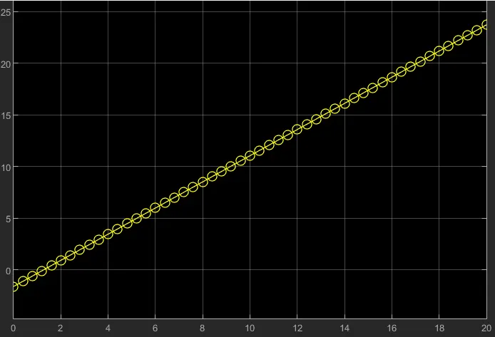
Figure04: Plot of speed of the motor against time.
Here we can observe the speed of the motor increases with increase in the values of the current and voltage.
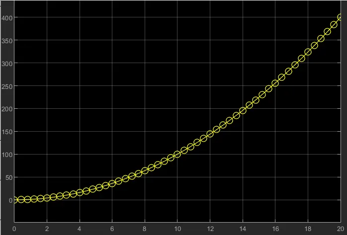
Figure05: Plot of electric power of the motor against time.
The eletric power of the motor is the product of the Current and Voltage thus this results in the curve nature of the plot over the given period of the time.
IV.
Author Wally Rippel explained the difference between the contruction of the DC brushless and Induction motors.
DC Brushless Motor:
In DC brushless motors consists of two or more permanent magnets that produces the DC magnetic fields.
This magnetic field enters the stator core which is made up of thin, stacked laminations.
Magnetic field interacts with the currents flowing through the conductor windings across the stator which produces a torque interaction between rotor and stator.
Rotor rotates continuosly which results in the continuos variation in the magnitude and polarity of the stator currents.
Maintaining the magnitude and polarity of the currents in just the right way we can converts the electrical energy into mechanical energy efficiently.
Inverter provides the current control of the DC brushless motors.
Induction Motor:
The stators of the three phase induction motor and the DC brushless motor are virtually identical, both have three sets of the "distributed windings" that are inserted within the stator core.
The essential difference between the two machines is with the rotors.
The rotor of the induction motor has no magnets whereas the rotor of the brushless motor consists of the permanent magnets.
The rotor of the induction motor is nothing but a stacked steel laminations buried peripheral conductors that forms a "shorted structure".
The currents flowing in the stator winding of the induction motor produces a rotating magnetic field that enters the rotor.
The frequency of the magnetic field w. r. t. rotor is equal to the difference between the electrical frequency and the rotational frequency of the rotor itself.
Thus a induced voltage exists across the shorted structure which is proportionate to the speed difference between the electrical frequency and rotational speed of the rotor.
In proportionate to this voltage the currents are produced in the rotor conductors that are approximately proportionate to the speed difference.
Finally these currents interact with the original magnetic field to produce the force component which is desired rotor torque.
Here we learnt the comparative construction and the working of the both motors so that we can understand the reason behind their application and shortcomings if any.
Scope for Improvisation:
The limitations and techniques to overcome them in each motor which are discussed below:
The induction motor has the ability to start under the load whereas DC brushless motor fails to produce the starting torque when directly connected to fixed frequency utility power.
For induction motor no inverter is needed whereas the DC brushless motor requires inverter whose phase is maintained in step with the angular position of the rotor.
For 3 phase induction motor AC supply is must and shaft speed is proportionate to the line frequency therefore can also be called as AC machines.
These 3 phase induction motors are constant speed machines, they have limited starting torque and somewhat limited running peak torque capabilities when compared to DC machines.
Add an inverter and it becomes possible to power an induction machine from a battery or other DC source.
Simply by adjusting the frequency of the inverter we can obatain speed variations in the speedof the induction motor.
Still the torque performance of an induction motor is noted on lower side when compare to the DC machines.
In order to improve the performance we can add feedback loops such that the inverter produces the exact frequency that the motor desires and now induction motor is capable of competing with the DC and DC brushless motor for vehicle applications.
Control codes for DC brushless motor and induction motor are given by Absolute position sensor and Speed sensor respectively.
With DC brushless drives less heat is generated.
Brushless drives can operate at unity power factor whereas the power factor for the induction drive is 85 percent.
Performance and Application:
When maximum torque is required, especially at low speeds, the magnetic field strength (B) should be maximum so that the inverter and motor currents are maintained at their lowest possible values.
This minimizes the I^2R losses and thereby optimes the efficiency.
Likewise when torque levels are low, the B fieldshould be reduced such that eddy and hysteresis and I^2R losses due to B are also reduced.
Ideally BB should be adjusted such that the sum of eddy, hysteresis and I^2r losses is minimized.
Unfortunately, there is no easy way of changing B with permanent magnets.
In constrast, induction machines have no magnets and B fields are "adjustable" since B is proportionate to v/f. This means at light loads inverter can reduce the voltage such that magnetic losses are reduced and efficiency is maximized.
Thus, the induction machine when operated with a smart inverter has an advantage over the DC brushless machine. Magnetic and conduction losses can be traded such that efficiency is optimized.
This advantage becomes increasingly important as performance is increased.
With DC brushless, as machine size grows, the magnetic losses increase proportionately and part load efficiency drops.
With induction, as machine size grows, losses do not necessarily grow.
Thus induction drive may be the favoured approach where high-performance is desired; peak efficiency will be a little less than DC brushless but average efficiency may actually be better.
Permanent magnets are expensive and their rotors are difficult to handle due to very large forces that come into play when anything ferromagnetic gets close to them.
Also due to field weakening capabilities of induction machines, inverter ratings and costs appear to be lower, especially for high performance drives.
Since spinning induction machines produce little or no voltage when de-excited, they are easier to protect.
The control laws of the induction motor are more complex and difficult to understand.
Achieving stability over the entire torque-speed range and temperature is more difficult with induction than DC brushless.
In this study we studied the induction and DC brushless motors to understand their specifications and field of applications.
We can use the DC brushless motor in Hybrid electric vehicle to optimize the performance of the vehicle.
And Induction motor in the Electric vehicles to obtain the required performance of the vehicle.
This is because of their behaviour under different operating conditions as we studied in this section. Still further improvements in the technology can lead us to the different results and conclusions. But so far it's very difficult to choose one of them over other.