Study of the equivalent circuit network of induction motor.
Aim: Study of the equivalent circuit network of induction motor.
Objectives:
To study and discuss about the equivalent circuit network of induction motor MATLAB model.Solve: 3 phase, 50 Hz induction motor, represented by equivalent circuit constants X1 = X2 = 0.1 ohm and R1 = R2 = 0.2 ohm is operated at half of rated voltage and frequency. Calculate the ratio of starting torque at half voltage & frequency to rated values.To study and make a comparison of square wave inverter output voltage with sine modulated one.
Introduction:
An induction motor is a well-known device which works on the principle of transformer. So it is also called the rotating transformer. That is, when an EMF is supplied to its stator, then as a result of electromagnetic induction, a voltage is induced in its rotor. So an induction motor is said to be a transformer with rotating secondary. Here, primary of transformer resembles stator winding of an induction motor and secondary resembles rotor.
The induction motor always runs below the synchronous or full load speed and the relative difference between the synchronous speed and speed of rotation is known as slip which is denoted by s.
`s = frac(Ns-N)(Ns)`
Where, Ns is synchronous speed of rotation which is given by-
`Ns = frac(120f)(p)`
Where, f is the frequency of the supply voltage.p is the number of poles of the machine.
Equivalent circuit for induction motor:
The equivalent circuit of any machine shows the various parameter of the machine such as its Ohmic losses and also other losses.
The losses are modeled just by inductor and resistor. The copper losses are occurred in the windings so the winding resistance is taken into account. Also, the winding has inductance for which there is a voltage drop due to inductive reactance and also a term called power factor comes into the picture. There are two types of equivalent circuits in case of a three-phase induction motor.
Exact Equivalent Circuit:
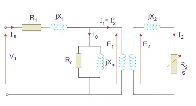
Fig01: Exact Equivalent Circuit for three phase induction motor.
Here, R1 is the winding resistance of the stator.X1 is the inductance of the stator winding.Rc is the core loss component.XM is the magnetizing reactance of the winding.R2/s is the power of the rotor, which includes output mechanical power and copper loss of rotor.If we draw the circuit with referred to the stator then the circuit will look like.
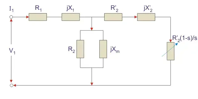
Fig02: Transferred rotor's parameters on stator side for Equivalent Circuit for three phase induction motor.
Here all the other parameters are same except-R2’ is the rotor winding resistance with referred to stator winding.X2’ is the rotor winding inductance with referred to stator winding.R2(1 – s) / s is the resistance which shows the power which is converted to mechanical power output or useful power. The power dissipated in that resistor is the useful power output or shaft power.
Approximate Equivalent Circuit:
The approximate equivalent circuit is drawn just to simplify our calculation by deleting one node. The shunt branch is shifted towards the primary side. This has been done as the voltage drop between the stator resistance and inductance is less and there is not much difference between the supply voltage and the induced voltage. However, this is not appropriate due to following reasons-
The magnetic circuit of induction motor has an air gap so exciting current is larger compared to transformer so exact equivalent circuit should be used.The rotor and stator inductance is larger in induction motor.In induction motor, we use distributed windings.
This model can be used if approximate analysis has to be done for large motors. For smaller motors, we cannot use this.
Power relation of an equivalent circuit:
Input power to stator- 3 V1I1Cos(Ɵ).Where, V1 is the stator voltage applied.I1 is the current drawn by the stator winding.Cos(Ɵ) is the stator power stator.Rotor input =Power input- Stator copper and iron losses.Rotor Copper loss = Slip × power input to the rotor.Developed Power = (1 – s) × Rotor input power.
Equivalent Circuit for Single Phase Induction Motor:
There is a difference between single phase and three phase equivalent circuits. The single phase induction motor circuit is given by double revolving field theory which states that-A stationary pulsating magnetic field might be resolved into two rotating fields, both having equal magnitude but opposite in direction. So the net torque induced is zero at standstill. Here, the forward rotation is called the rotation with slip s and the backward rotation is given with a slip of (2 – s). The equivalent circuit is
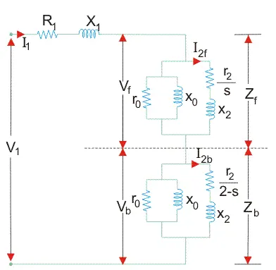
Fig03: Equivalent Circuit for single phase induction motor
In most of the cases the core loss component r0 is neglected as this value is quite large and does not affect much in the calculation.Here, Zf shows the forward impedance and Zb shows the backward impedance.Also, the sum of forward and backward slip is 2 so in case of backward slip, it is replaced by (2 – s).R1 = Resistance of stator winding.X1 = Inductive reactance of the stator winding.Xm = Magnetising reactance.R2’ = Rotor Reactance with referred to stator.X2’ = Rotor inductive reactance with referred to stator.
Power calculations for equivalent circuit:
Find Zf and Zb.Find stator current which is given by Stator voltage/Total circuit impedance.Then find the input power which is given byStator voltage × Stator current × Cos(Ɵ)Where, Ɵ is the angle between the stator current and voltage.Power Developed (Pg) is the difference between forward field power and backward power. The forward and backward power is given by the power dissipated in the respective resistors.The rotor copper loss is given by- slip × Pg.Output Power is given by-Pg – s × Pg – Rotational loss.The rotational losses include friction loss, windage loss, Core loss.Efficiency can also be calculated by diving output power by input power.
Square wave inverter working:
A switching circuit is used in the conversion of DC voltage to an alternating (or bipolar) square wave voltage. One method is the use of the inverter bridge (also known as an H-bridge), which is illustrated in Figure 4.
The switch symbols are used to represent switching transistors (IGBTs or MOSFETs) or other types of electronic switching devices. In Figure 4a, switches S2 and S3 are on for a specified time and S1 and S4 are off.
To produce a 60 Hz square wave, each pair of switches is on for half of the period, which is 8.33 ms.
As you can see, the direct current is through the load, which creates a positive output voltage. In Figure 4b, opposite switches are on and off. The current is in the opposite direction through the load, and the output voltage is negative. The complete on/off cycle of the switches produces an alternating square wave.
The transistors are switched by a timing control circuit, which is not shown for simplicity. The harmonic distortion of a typical square wave output is in the range of 45%, which can be reduced somewhat by filtering out some of the harmonics.
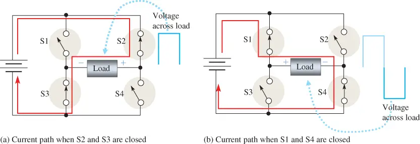
Fig04: Inverter Bridge. The inverter bridge (H-bridge) is a method of producing a square wave from a DC voltage.
Modified Sine Wave Inverter working:
The operation of a basic H-bridge is enhanced to produce the misnamed modified sine wave, which is shown in Figure 5. (Perhaps modified square wave would be a better name.)
The resulting wave is far from resembling a sine wave despite the name and cannot be used for some types of loads. The wave is created from a square wave and adds a short dead time between positive and negatives excursions of the square wave.
Although the resulting output is definitely not a sine wave, the harmonic distortion is reduced to 24% compared to a pure square wave’s 45%. This is still a significant amount of distortion. Filtering can reduce this distortion; however, filtering also significantly reduces the power to the load and thus reduces the efficiency.
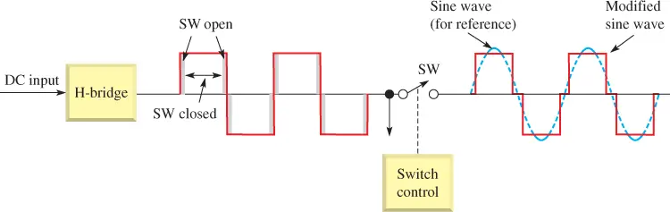
Fig05: Concept of a Modified Sine Wave Inverter.
Note that a so-called modified sine wave with only two levels cannot be used for driving many types of loads, including some electronic devices (some computer power supplies are an exception) and cannot be used to send to the grid.
Appliances that have electronic speed controls (such as mixers) or those with timers may have problems and may be damaged from the modified sine wave.
Also, anything with a motor may not run as efficiently as it would with a pure sine wave. In addition, noise may be generated due to fast transitions in the waveform. This can result in buzzing in speaker systems. As a result of these problems, the modified sine wave has limited use.
Problem Statement:
Discuss about the equivalent circuit network of induction motor MATLAB model.3 phase, 50 Hz induction motor, represented by equivalent circuit constants X1 = X2 = 0.1 ohm and R1 = R2 = 0.2 ohm is operated at half of rated voltage and frequency. Calculate the ratio of starting torque at half voltage & frequency to rated values.Make a comparison of square wave inverter output voltage with sine modulated one.
Solution:
1.
Discuss about the equivalent circuit network of induction motor MATLAB model.
Stator and rotor are the main pans of the induction motor. The voltage is applied to the motor based on the phase. The following figure shows the equivalent circuit for the induction motor. Current flows to the stator resistance which is less than the rotor resistance. Slip occurs if the force on the shaft is more and where the synchronous speed is greater than the relative speed.
The equivalent circuit of any machine shows the various parameter of the machine such as its Ohmic losses and also other losses.
The losses are modeled just by inductor and resistor. The copper losses are occurred in the windings so the winding resistance is taken into account. Also, the winding has inductance for which there is a voltage drop due to inductive reactance and also a term called power factor comes into the picture.
Fig06: Transferred rotor's parameters on stator side for Equivalent Circuit for three phase induction motor.
Here,
R1 is the winding resistance of the stator.X1 is the inductance of the stator winding.XM is the magnetizing reactance of the winding.
R2’ is the rotor winding resistance with referred to stator winding.
X2’ is the rotor winding inductance with referred to stator winding.
R2(1 – s) / s is the resistance which shows the power which is converted to mechanical power output or useful power. The power dissipated in that resistor is the useful power output or shaft power.
Power relation of an equivalent circuit:
Input power to stator- 3 V1I1Cos(Ɵ).Where, V1 is the stator voltage applied.I1 is the current drawn by the stator winding.Cos(Ɵ) is the stator power stator.Rotor input =Power input- Stator copper and iron losses.Rotor Copper loss = Slip × power input to the rotor.Developed Power = (1 – s) × Rotor input power.
2.
3 phase, 50 Hz induction motor, represented by equivalent circuit constants X1 = X2 = 0.1 ohm and R1 = R2 = 0.2 ohm is operated at half of rated voltage and frequency. Calculate the ratio of starting torque at half voltage & frequency to rated values.
Given data:
3-Phase Induction motor.
Frequency (f): 50 Hz
X1 = X2 = 0.1 ohm
R1 = R2 = 0.2 ohm
Assume:
Applied voltage = V
Number of poles = P = 4
Starting torque equation for 3-phase induction motor:
`Ts = frac(3*(V^2)*R2)(omegams*((R1+R2)^2+(X1+X2)^2)`
Synchronous speed of motor:
`Ns = frac(120*f)(P)`
Synchronous speed of motor (rad/sec):
`omegams = 2pi*Ns`
To find:
Ratio of starting torque at half of rated voltage and frequency to the rated values of voltage and frequency.
Solution:
Case-1) Starting torque for half of the rated voltage and frequency:
`V = frac(V)(2)`
and
`f = frac(50)(2) = 25 Hz`
As we know that;
`Ts = frac(3*(V^2)*R2)(omegams*((R1+R2)^2+(X1+X2)^2)`
substituting given we get;
`Ts = frac(3*(V/2)^2*0.2)(frac(120*25)(4)*2Pi*((0.2+0.2)^2+(0.1+0.1)^2)`
`Ts = (7.956e-5)*(V^2)*P`
...equation (a)
Case-2) Starting torque for the rated voltage and frequency:
`V = V`
and
`f = 50 Hz`
As we know that;
`Ts = frac(3*(V^2)*R2)(omegams*((R1+R2)^2+(X1+X2)^2)`
substituting given we get;
`Ts = frac(3*V^2*0.2)(frac(120*50)(4)*2Pi*((0.2+0.2)^2+(0.1+0.1)^2)`
`Ts = (3.978e-5)*(V^2)*P`
...equation (b)
Calculating the ratio of starting torque, dividing equation(b) by equation(a).
`Ts = 0.5`
3.
Make a comparison of square wave inverter output voltage with sine modulated one.
Square wave output of an inverter:
The function of an inverter isto convert the straight line DC voltage into AC voltage. For this operation the inverter uses the it's circuit configuration to produce the nearly close replica (square wave) output but alternating. During this phase of the output wave the output is nothing but a number of frequencies grouped together thus we get the square wave as a output.
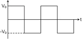
Fig07: Square waveform.
Sine wave output of an inverter:
This grouped number of frequencies is then ungrouped by using fourier's transformation. Which results in modulated squares. The width of the squares is maintained such that it gradually increases from the beginning of the pulse towards the centre and then again gradually decreases towards the end of the pulse.This is done to obtained the sine nature of the output curve. The amplitude of the sine is maximum at maximum modulated width of the square. Thus it is called as modulated square wave or sine wave.
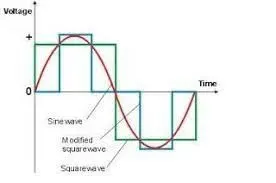
Fig08: Modulation of square wave into sine wave.
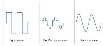
Fig09: Representation of different waveforms.
List of Features |
Square Wave |
Sine Wave |
Supported Appliances |
Square wave inverters are usually used to support motors alone. |
Sine wave inverters are used to support household appliances such as refrigerators ovens, computers, laptops, etc. |
Overall Safety Level |
Square wave inverters are less reliable and also unsafe to use for appliances. |
Sine inverters are highly safe to use. |
Noise Interference |
Square wave inverters produce a very loud noise when used. |
Sine wave inverters produce normal sound only. |
Cost |
Square wave inverters are less expensive than Sine wave inverters. |
Sine wave inverters are more expensive than Square wave inverters. |
Table01: Comparision of square wave inverter output voltage with sine modulated one.
Conclusion:
In this study we learnt the concept of the equivalent circuit for three phase induction motor. We also studied starting torque and it's calculations for the induction motor for different values of the ratedd voltage and frequency. Comparision of the sine waveform with square waveform is also made to know the difference of both inverter output voltages.