Study of speed torque characteristics and frequency control method of an induction motor by using matlab.
Aim:
Study of speed torque characteristics and frequency control method of an induction motor by using matlab.
Objectives:
1. How induction motor operation is similar to the clutch?
2. Calculate the starting time of a drive with the following parameters:
J=10 kg-m2,
T = 15 + 0.5wm
Tl=5+0.6ωm
3. A drive has following equations for motor and load torques:
Tm=(1+2ωm)
Tl= 3 √ωm
Obtain the equillibrium points and determine the stability.
4. Make a MATLAB script file which will plot speed-torque characteristics for frequency control method.
Introduction:
Induction Motor:
An Induction motor is the most widely used AC motor in industrial and domestic applications. Moreover, it has good operating characteristics with an efficiency as high as 90%. An induction motor does not have any commutator, like the one we saw in a DC motor. Hence it provides a good speed regulation without any sparking.
Construction of Induction motor:
An Induction motor consists of a frame, stator core, rotor, shafts, and bearings.
Frame:
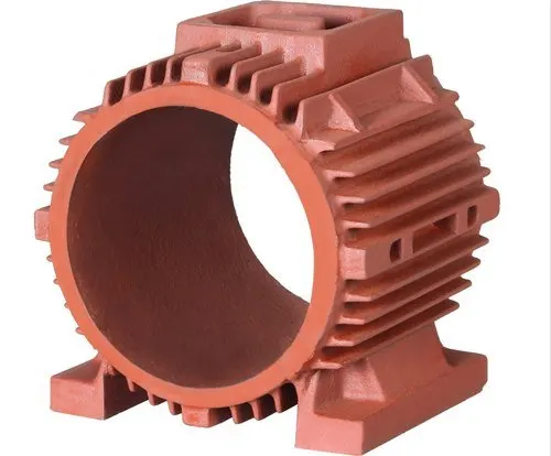
Fig01: A frame of an Induction Motor.
It is the outer body of the motor. It supports the stator core and protects the inner parts of the machine from the surroundings.
Stator core:
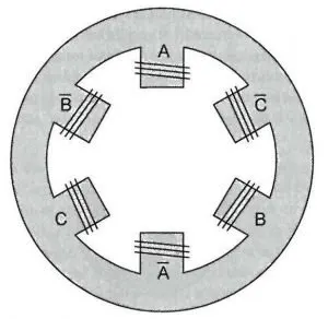
Fig02: 120 degrees displaced three-phase winding on Stator.
A stator consists of a stack of laminations of silicon steel in the form of a ring. It fits inside the stator frame and contains slots on its inner periphery. These slots carry the three-phase winding, separated by 120 degrees in space. Right here, the figure shows the distribution of three-phase winding in a stator.
Rotor:
A rotor consists of a stack of laminations in the form of a cylinder. It has slots punched on its outer periphery, which contains rotor windings. Based on the winding type, there are two categories of rotors.
Squirrel cage rotor:
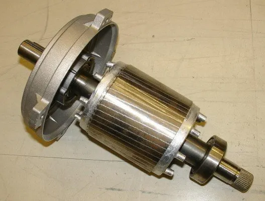
Fig03: A Squirrel cage rotor of the Induction motor.
This rotor uses copper or aluminum bars as the rotor conductors. Each slot of the rotor carries a conductor without any insulation from the core. All the conductors are shorted by annular rings, aka end rings.
Wound rotor:
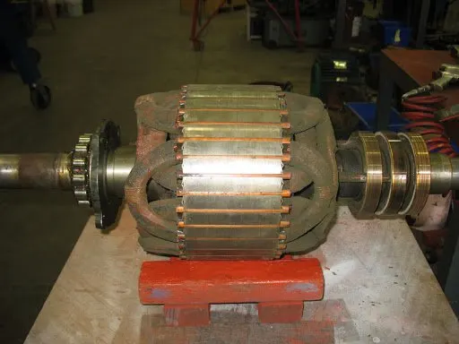
Fig04: A Wound rotor of an Induction motor.
It uses wires or straps for the rotor windings. The distribution of the three-phase winding on the rotor is similar to that of the stator. The winding connects to an external resistance through slip rings and brushes. The wound rotor provides a higher starting torque as compared to the squirrel cage rotor.
Shaft and Bearings:
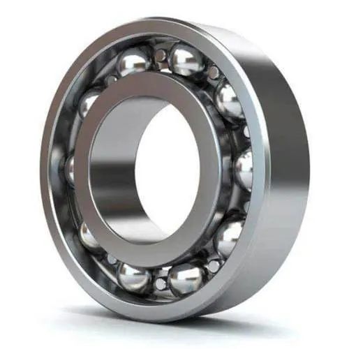
Fig05: Ball and roller bearings.
The induction motor uses ball-and-roller bearings. These bearings support the rotor shaft and make it rotate smoothly.
Working Principle:
The induction motor follows these two laws to generate a unidirectional torque.
Faraday's law of electromagnetic indiction:
It states that a conductor placed in a varying magnetic field induces an Electromagnetic force (EMF). The closed conductor leads to the flow of current, known as induced current.
Lorentz force law:
It states that a current-carrying conductor placed in a magnetic field experiences a force. The force on the conductor is orthogonal to the direction of the current and magnetic field.
The concept of rotating magnetic field:
The creation of a rotating magnetic field requires two essential conditions:
A three-phase distributed winding. The axis of the windings must make a space angle of 120 degrees.A three-phase AC source. The magnitude of current in the three phases is equal but is displaced in time by 120 degrees. The figure here shows a sinusoidal wave of a three-phase source. See how each phase current achieves its peak value at different times.
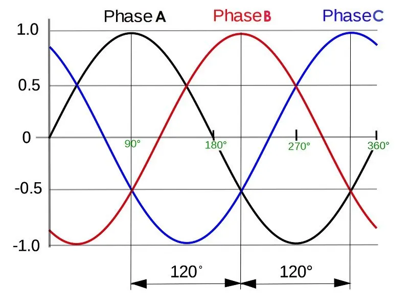
Fig06: Three-phase sinusoidal AC waveform.
When we give this three-phase supply to the stator windings, the windings start creating a magnetic flux. The figure below shows the orientation of magnetic flux by the three phases after giving a three-phase supply.
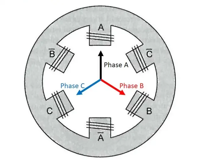
Fig07: The orientation of magnetic flux by the three phases.
But as the current from the three-phase source achieves its peak value at different instant of time, the magnetic flux will follow the same behavior. Let us see how. Consider these time instants X, Y, and Z in the waveform.
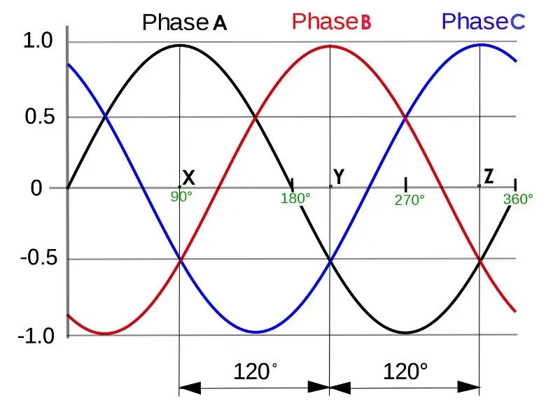
Fig08: Three selected time intervals, i.e., X, Y, and Z.
Magnetic field vector orientation at selected instants:
At point X:
At point X, the current magnitude in phase A is more compared to phases B and C. Moreover, the Phase A current is positive, while the current in Phases B and C is negative. So, if we represent the magnetic field vectors at point X, it looks like this. Note the direction of the resultant magnetic field.
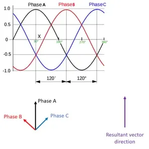
Fig09: The alignment of magnetic field vectors at moment X.
At point Y:
At point Y, the current magnitude in phase B is more as well as positive. The figure below shows the orientation of the magnetic field vectors at point Y. In this case, the direction of the resultant magnetic field has changed.
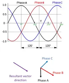
Fig10: The alignment of magnetic field vectors at moment Y
At point Z:
At point Z, the current magnitude in phase C is more and positive. The vector representation of the magnetic field looks like this. Note that the direction of the resultant magnetic field has again changed.
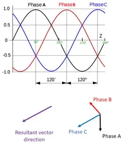
Fig11: The alignment of magnetic field vectors at moment Z.
From the above three time instants, we conclude that the resultant magnitude of the magnetic field always remains uniform, but its direction changes periodically. On tracing the trajectory of the magnetic field vector, we obtain a circle.
Hence, the application of three-phase current to the three-phase distributed winding creates a rotating magnetic field. The field rotates with a constant speed known as synchronous speed.
How does the rotor rotate in an induction motor?
So, after the generation of the rotating magnetic field, the rotor conductors start interacting with the magnetic field. Assume a rotor conductor interacting with the magnetic field as shown in the figure.
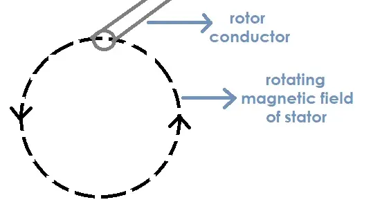
Fig12: Interaction of rotating magnetic field with rotor conductor.
This interaction induces a current in the conductor (according to Faraday’s law of electromagnetic induction). Now, according to Lorentz law, a force starts acting on the conductor. This force tends to displace the rotor in a direction, as shown in the figure.
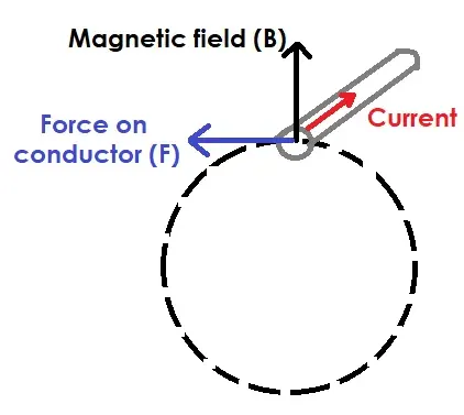
Fig13: The direction of the force on the rotor conductor.
And the rotor slowly begins to accelerate and try to attain the stator’s synchronous speed.
From this, we conclude that the induction motor is self-starting and requires only a single excitation source.
What happens if the rotor attains the synchronous speed?
So, when the rotor starts rotating, a wide relative speed lies between the stator’s magnetic field and the rotor conductors. As the rotor accelerates, this relative speed starts decreasing. Hence, the current in the rotor conductor starts reducing.
Now, assume that the relative speed between them becomes zero, and the rotor starts rotating with synchronous speed. As this happens, the magnetic field no longer interacts with the rotor conductors. And hence, no current flows in the rotor conductors. As a consequence, no force acts on the rotor conductors. So, the rotor speed will get reduced. The rotor always tries to catch the synchronous speed but never attains it.
Thus we conclude that an induction motor always runs at a lesser Speed than synchronous speed. Hence it is also known as the Asynchronous motor.
What is Slip?
So, we saw that there always lies a speed difference between the rotating magnetic field and the rotor conductors. This speed difference is known as Slip. If we denote the synchronous speed with (Ns) and the rotor speed with (Nr), then the Slip (s) is given by
`s = frac(Ns- Nr)(Ns)`
The value of the Slip always ranges between 0 and 1.
What is Clutch?
A clutch is a mechanical device which engages and disengages power transmission from the gearbox of an automobile.
A clutch is a part of the transmission system which receives power from the engine via the Flywheel and transmits this power to the gearbox of the automobile to drive the wheels.
What is the need of a clutch?
Now let us take an example of a car. Imagine you are driving a car and you need to change gears, now if a clutch isn’t present you would have to stop the car let the engine come to rest and then change the gear or else the gears would get damaged if changed in motion.
This would be very hectic and impractical. So if a clutch was present you can disconnect the engine and the transmission and then change the gear without having to stop the car. This is why clutches are so important. Single Plate Clutch Construction and Working:
This is the most common and widely used clutch in automobiles. The important components of single plate clutch are :
FlywheelClutch platePressure plateClutch springsThrust bearing
Flywheel :
Flywheel is a disc of heavy mass and bolted to the engine crankshaft. The flywheel is a flat disc and is in contact with the clutch plate or friction plate.
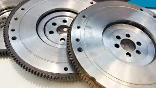
Fig14: Flywheels.
Clutch plate :
Clutch plate is a metal disc with friction linings on both of of its surfaces. It has a central hub which is machined internally so that it can slide to and fro on a splined shaft.
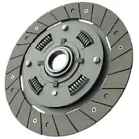
Fig15: Clutch plate.
Pressure Plate :
It is a heavy mass plate which makes sure that the flywheel and the friction plate are in good contact of each other to ensure smooth power transmission.
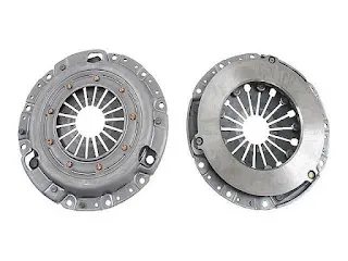
Fig16: Pressure plates.
Clutch springs :
These springs are radially mounted over the pressure plate to ensure that the plates are in engaged position when the clutch pedal is at rest. When the clutch pedal is pressed by the driver these springs are compressed hence the clutch is disengaged.
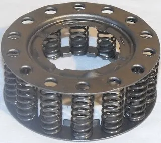
Fig17: Clutch springs.
Thrust bearing :
This bearing handles the axial load which comes during sudden release of the clutch springs. They help in dampening and provide seamless operation.
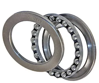
Fig18: Thrust bearing.
Working of the Singke Plate Clutch:
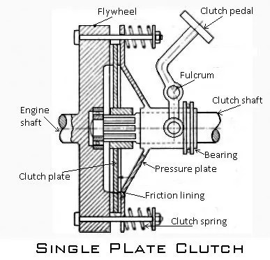
Fig19: Single Plate Clutch. When the clutch is in the engaged position: i.e. the clutch pedal is not pressed by the driver. This condition is refered as clutch pedal position-up. When the pedal position is up, the actual force applied by the clutch springs causes the flywheel, friction plate and pressure plate to be sandwiched together.Thus, the drive is engaged and power is transmitted from the engine to the transmission system (gearbox) and hence the wheels of th car move forward.
When the clutch is in disengaged position:
In this position the driver presses the clutch-pedal. This causes the pressure plate to overcome the force of the springs. Due to this the contact between the pressure plate and flywheel is loosen up.Therefore, the drive gets disengaged and power is not transmitted from the engine to the transmission system (gearbox).
Steady State Stability:
The equation for variation in speed for linear motion:
`F = m*a`
F = Force in N
m Mass in Kgs
a = Acceleration in m/s^2
The equation for variation in speed for rotary motion:
`T = J*frac(deltaomega)(deltat)`
T = Torque in N.m
J = Moment of inertia kg/m^2
ω = Angular velocity in rad/sec
t = Time in seconds.
When motor torque and load torque are corelated to calculate the net torque:
`Tm-Tl = J*frac(deltaomega)(deltat)` .....equation 01
Tm = Motor Torque in N.mTl = Load Torque in N.mequation 01 is the fundamental equation of the motor drive.
Stability condition for the motor drive system:
`frac(deltaTl) (deltaomega) - frac(deltaTm) (deltaomega) gt 00`
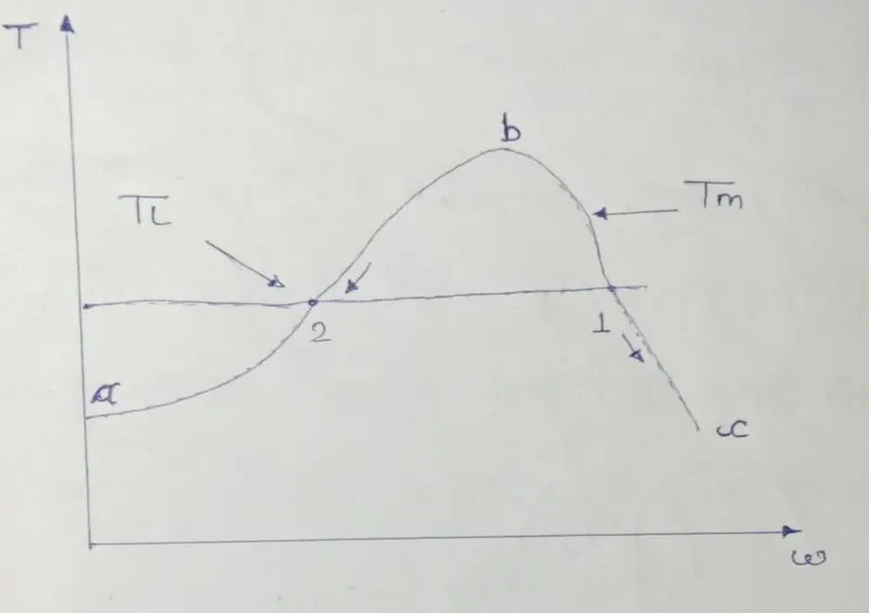
Fig20: Characteristic diagram for operating points.
bc: Stable Operation
ab: Unstable Operation
Stability means motor will drive the load sufficiently.
For boundried input and boundried output:
If the speed of motor is increasing positively then the load torque should limit that rise in speed.
`if, delta omega gt 00`
`TlgtTm`
Whereas if the speed of the motor is decreasing then the motor torque should not allow the motor to reach it's zero speed.
`if, delta omega lt 00`
`Tm gt Tl`
Therefore, For Point-01:
With increase in speed load torque is greater than motor torque. That means motor will drive the load. Hence it's a stable condition and considered.
For Point-02:
With decrease in speed motor torque is greater than the load torque that means motor will not cope up with the load. Hence it's a unstable condition which is not considered.
Solution:
01.
How induction motor operation is similar to the clutch?
Let's consider the input power is given to the driving shaft which is further transmitted to the driven shatf if the clutch is in engaged position.
On one side if the driving shaft is rotating in clockwise direction and the torque produced by it is T and angular velocity is ω1 (rad/sec).
And on other side if the driven shaft is rotating in same direction and produces same torque T with angular velocity of ω2 (rad/sec) which is slightly different due to effect of slip.
Under ideal condition the ω1 and ω2 are same. And the power available on the both the sides is same too.
But if we introduce the concept of slip then the actual situation comes into the picture.
Slip is nothing but the percentage of difference between the speeds of both the shafts w. r. t. speed of input shaft.
Mathematically, `S = frac(omega1-omega2)(omega1)` ...equation 01
S Slip.
For ω2 equation 01 can be written as
`omega2 = omega1(1-S)` ...equation 02
ω1 = Speed of the driving shaft in rad/sec.
ω2 = Speed of the driven shaft in rad/sec.
Equation 02 is similar to the equation of speed of the induction motor which is given as:
`omegam = omegams(1-S)` ...equation 03
ωm = Actual speed of the motor in rad/sec.
ωms = Synchronous speed of the motor in rad/sec.
Losses due to slip inside the motor:
if
Pr = Input power supplied to the motor in watts.
Pcr = Copper losses inside the rotor.
Pm = Mechanical power available at rotor's output in watts.
Therefore,
`Pr:Pcr:Pm = 1:S:1-S`
Losses due to slip in clutch:
Loss = Input power - Output power
`Loss = Tomega1 - Tomega2`
`Loss = Tomega1 - T(omega1(1-S))`
`Loss = (1-S)T`
02.
Calculate the starting time of a drive with the following parameters:
J=10 kg-m2,
Tm = 15 + 0.5ωm
Tl = 5 + 0.6ωm
Steady State equation for induction motor is given as:
`Tm-Tl = J*frac(deltaomega)(deltat)` ....equation 01
Where,
Tm = Motor Torque in N.mTl = Load Torque in N.mJ = Moment of inertia of the motor and the load system combined kg/m^2ω = Angular velocity rad/sect = Time in seconds.Therefore, substituting given values of Tm and Tl in equation 01 we get: ....equation 02Now we'll have to find the value of ωm:According to given data:Tm = 15 + 0.5ωm
Tl = 5 + 0.6ωm
At steady state motor torque is equal to the load torque:
Therefore;
`Tm=Tl`
`15+0.5omegam = 5+ 0.6omegam`
`0.1omegam = 10`
`omegam = 100 (rad)/(sec)`
Assuming the 5 % of slip the equilibrium speed will decrease from 100 rad/sec to 95 rad/sec.
For starting of the motor:
ωm0 = 00 rad/sec
ωme = 95 rad/sec
Now, integrating the equation 02 on both sides and in RHS the intervals are taken as ωm0 and ωme ,
`intdeltat = int_0^95 frac(1)((1-0.01omegam))*deltaomega`
`t =(frac(1)(0.01))*ln|1-0.01(omegam)|` ... equation 03
Applying the interval values to equation 03:
`t = [(frac(1)(0.01))*ln|1-0.01(95)|] - [(frac(1)(0.01))*ln|1-0.01(00)|]`
`t = 299.57` seconds
Therefore the time required for an induction motor drive to start is 299.57 seconds.
03.
A drive has following equations for motor and load torques:
`Tm = (1+2omegam)`
`Tl = root(3)(omegam)`
Obtain the equillibrium points and determine the stability.
For the stability of an induction motor drive:
`frac(deltaTl) (deltaomega) - frac(deltaTm) (deltaomega) gt 00`
`frac(deltaTl) (deltaomega) = frac(3)(2sqrt(omegam))`
`frac(deltaTm) (deltaomega) = 2`
Therefore;
`frac(3)(2sqrt(omegam)) - 2 gt 00` ...equation 01
Now let's find the value of ωm:
For stability Tl = Tm
`root(3)(omegam) = 1+2omegam`
`2omegam - root(3)(omegam) + 1 = 00`
Squaring both side we get:
`4omegam^2 - 5omegam + 1 = 00`
ωm1 = 0.25 and ωm = 1.
Substituting ωm1 = 0.25 in equation 01:
`frac(3)(2sqrt(0.25)) - 2 = 1`
Therefore satisfied.
Therefore at point ωm1 = 0.25 stability is achieved
Substituting ωm1 = 1 in equation 01:
`frac(3)(2sqrt(1)) - 2 = -0.5`
Condition failed.
04.
Make a MATLAB script file which will plot speed-torque characteristics for frequency control method.
Matlab script for IMD control by VFDM.
clear all
close all
clc

% Inputs
% Voltage per phase
V = 230/sqrt(3);

% Number of phasses
ph = 3;

% Number of poles
p = 4;

% Stator resistance and inductance
R1 = 0.095;
X1 = 0.680;

% Rotor resistance and inductance
R2 = 0.23;
X2 = 0.672;

% Magnetizing inductance
Xm = 18.7;

% calculate stator equivalent resistance
Zeq = 1i*Xm*(R1+1i*X1)/(R1+1i*(X1+Xm));
Veq = abs(V*1i*Xm/(R1+1i*(X1+Xm)));

% Frequencies
Fz = linspace(10,50,5);

for i = 1:5

    % Motor speed calculations
    w = (4*3.14*Fz(i))/p;
    Ns = (120*Fz(i))/p;

    for n = 1:100

        % Slip
        s(n) = n/100;

        % Motor speed in rpm
        W(n) = Ns*(1-s(n));

        % Current in rotor
        I2 = abs(Veq/(Zeq+1i*X2+R2/s(n)));

        % Torque calculations
        T(n) = ph*I2^2*R2/(s(n)*w);
    end

    % To display maximum speed of the motor at different frequencies.
    Curve = ['The maximum speed of motor at',num2str(Fz(i)),'Hz'];
    disp(Curve)
    disp(W(1))

    % Plot
    plot(W,T,'linewidth',2.2);
    hold on
    axis ([0 1500 0 600])
    title('Torque-Speed characteristics of Induction Motor');
    xlabel('speed(rpm)');
    ylabel('Torque(N-m)');
end
legend('10','20','30','40','50');
grid on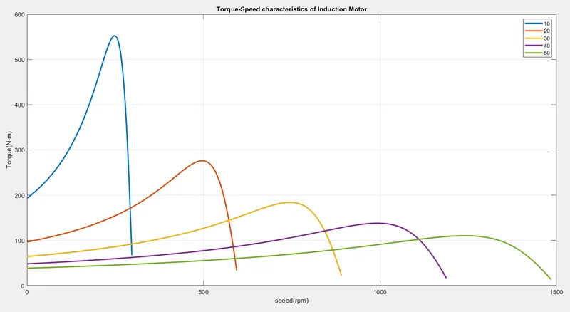
Fig21: Torque speed Characteristic diagram for matlab script.
In input section we entered the given data.We performed the 'for loop' which will perform the calculations for the torque and the motor speed.Since we have a array of five frequencies and their values each frequency will correspond to specific synchronous speed hence the length of the frequency is taken.For second loop thr range from 1 to the length of the slip array is taken which means we will get an torque output of 100 values with each value corresponding to the slip value.Slip terms from the torque formula will be replaced with the values from the slip array and the synchronous speeds calculated in the first for loop will also be included.In the end the modifications are done to plot the title, axis, labels and the legend key to show that each torque-speed characteristic belongs to the particular frequency.
Conclusion:
In this study we learnt the comparision of the induction motor with the mechanical cluth and their similarities in terms of concept of slip. We also learnt to calculate the starting time of an induction motor drive and the plotting of equilibrium points and determining their stability. Finally we studied the matlab program to plot the torque-speed characteristics of an induction motor by using frequenct control drive.