Analysis & Design of RCC shear walls in the model using ETABS
Analysis & Design of RCC shear walls in the model using ETABS
QUESTION:-
The etabs file for a G+6 building is provided. Run the analysis and design the RCC shear walls (show in the etabs model). The following challenge deals specifically with the shear wall of size 300x1500 at grid A-11 in the structural model.
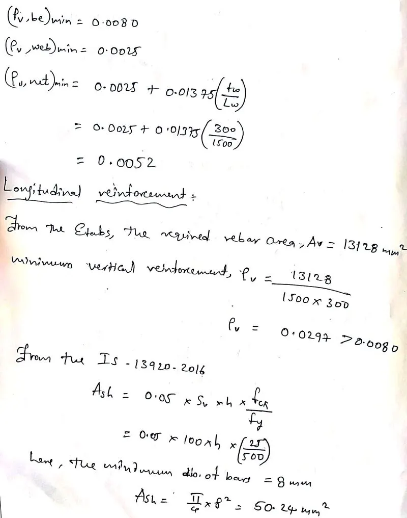
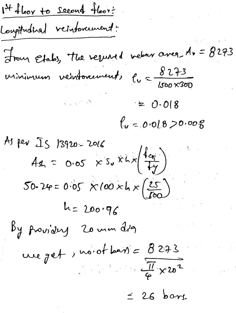
- Extract values of longitudinal steel ratio, boundary element length and shear reinforcing ratio from the design results.
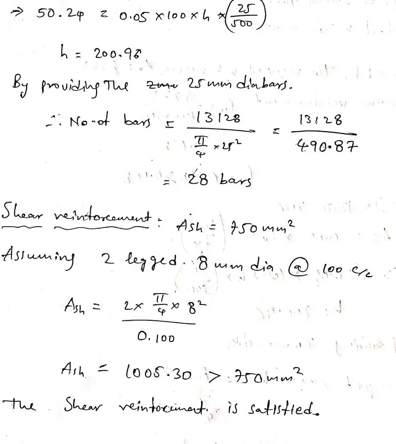
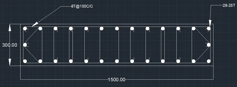
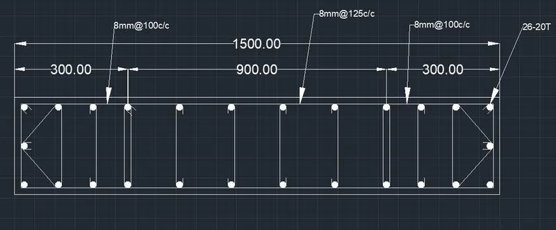
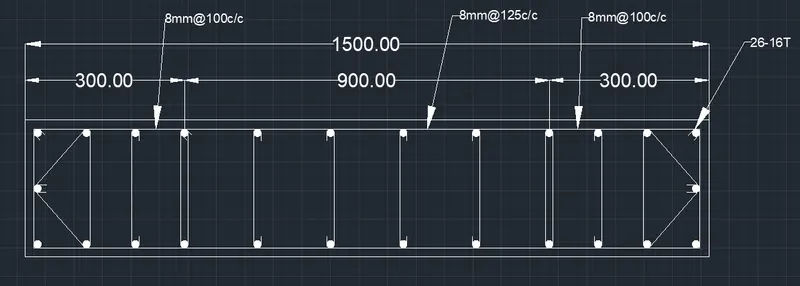
- Provide cross sectional steel arrangement of the shear wall from its base up to terrace, in compliance with provisions of IS 13920 – 2016. AutoCAD application can be used for this exercise. Alternatively, it can be drawn by hand as well.
- Provide drawings of the reinforcement details of the shear wall from base up to terrace.
ANSWER:-
Aim:- To provide,
The cross sectional steel arrangement of the shear wall from its base up to terrace, in compliance with provisions of IS 13920 – 2016.
The drawings of the reinforcement details of the shear wall from base up to terrace.
Introduction:-
- Shear walls are vertical elements of the horizontal force resisting system.
- They are constructed to counter the effects of lateral load acting on a structure.
- When shear walls are designed and constructed properly, and they will have the strength and stiffness to resist the horizontal forces.
- Shear walls are especially important in high- rise buildings subjected to lateral wind and seismic forces.
- Shear walls are not only designed to resist gravity / vertical loads, but they are also designed for lateral loads of earthquakes / wind.
Procedure:-
Step:-1
- First we have to open the challange 9 page and download the challenge.
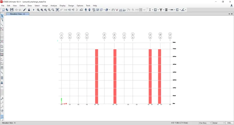
- After downloading the Challenge open it in the etabs 2018, as shown below.
- Next we have to do the run analysis.
Step:-2
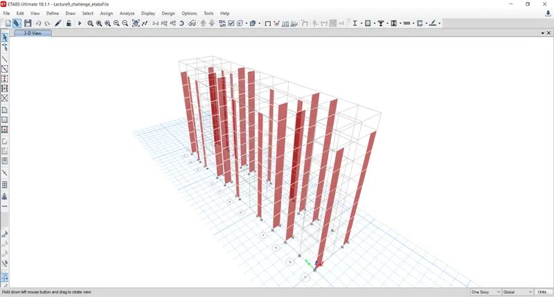
- Next we need to keep the model in the 3-dimensional view, as shown below.
Step:-3
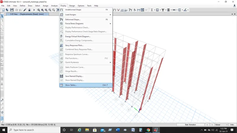
- Next, from the display option we select the show tables option, as shown below.
Step:-4
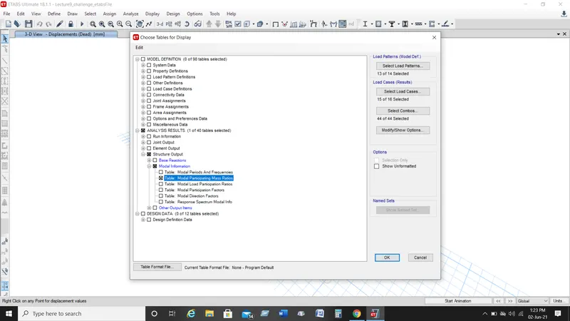
- After selecting the show tables option the new tab will be visible.
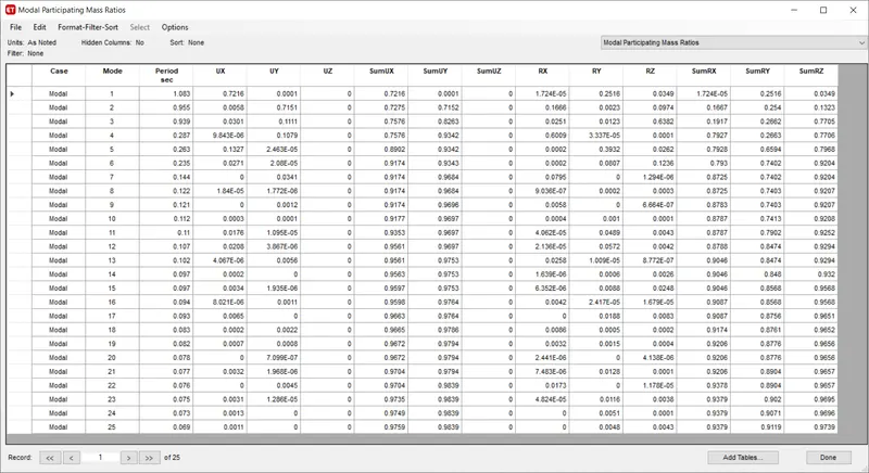
- Now we select the Modal Participating Mass Ratios and click on the ok button, as shown below.
Step:-5
- Next the Modal Participating Mass Ratios table will be visible, as shown below.
Step:-6
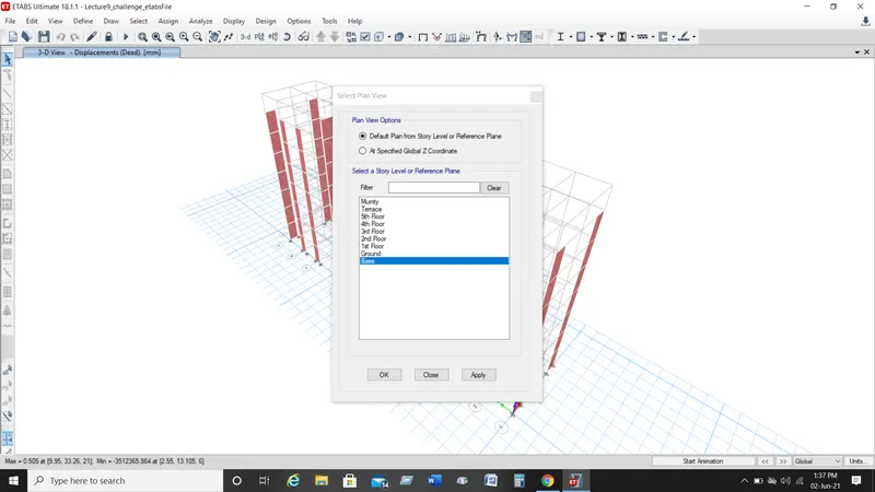
- Next we open the select plan view tab and select the base floor, as shown below.
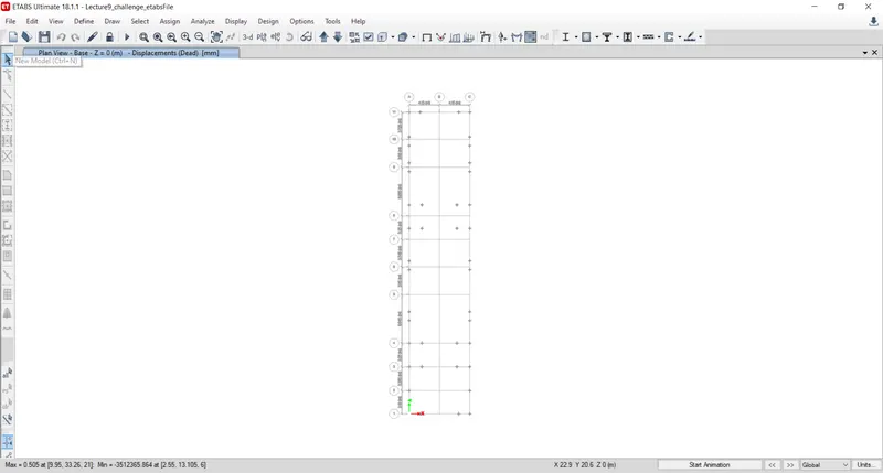
- Next the base floor plan will be visible, as shown below.
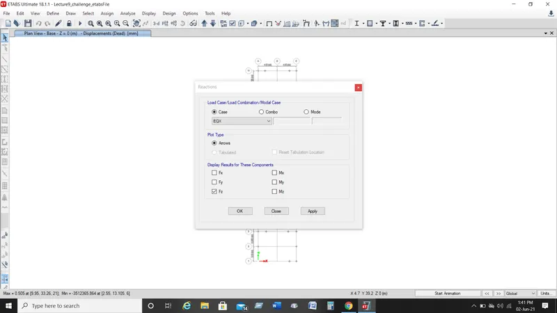
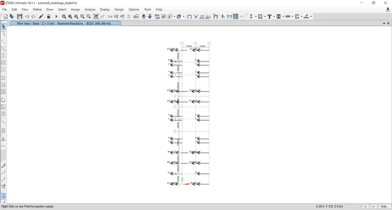
- Next we have to open the reactions tab, then we select the eartquake load towards X-direction(EQX) in the load case, then click on the ok buttion as shown below.
- Now the base shear reactions will appear, as shown below.
- When we divide the base shear taken up by the shear wall divided by the total base shear of building will get the % of the shear forces taken up by the shear wall.
- And if that is less than 80%, that is more shear wall is required.
Step:-7
- Next, from the display option we select the show tables option, as shown below.
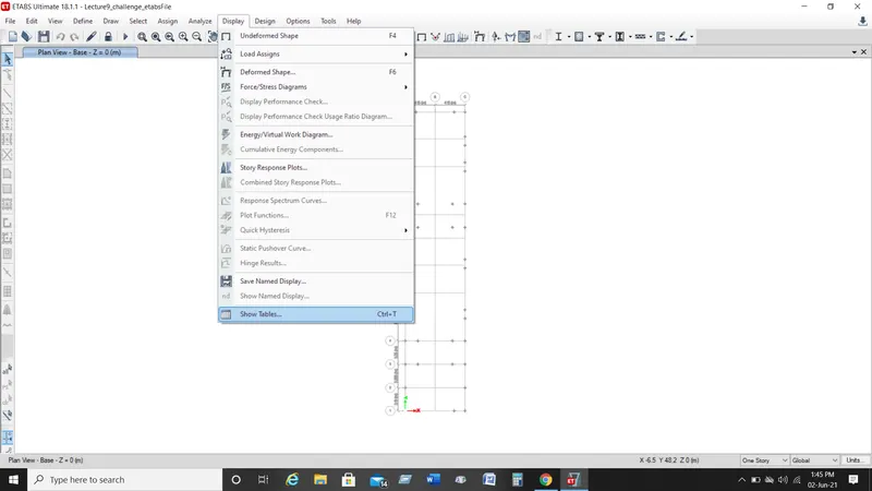
- After selecting the show tables option the new tab will be visible.
- Now we select the Base Reactions and click on the ok button, as shown below.
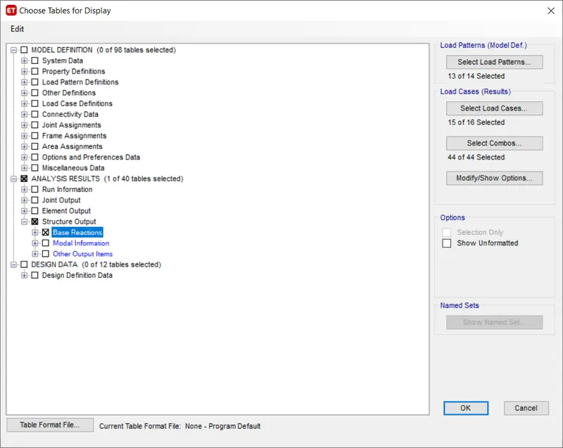
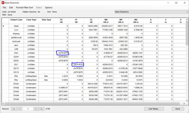
- Next the Base Reactions table will be visible, as shown below.
- In the below table, the total base shear of EQX and EQY will be taken for the calculating the % of the shear forces taken up by the shear wall.
Step:-8
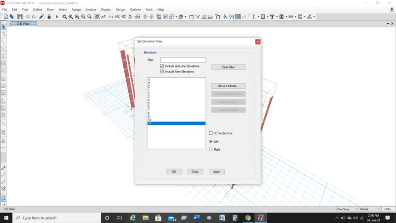
- Next we open the select elevation view tab and select the 11, as shown below.
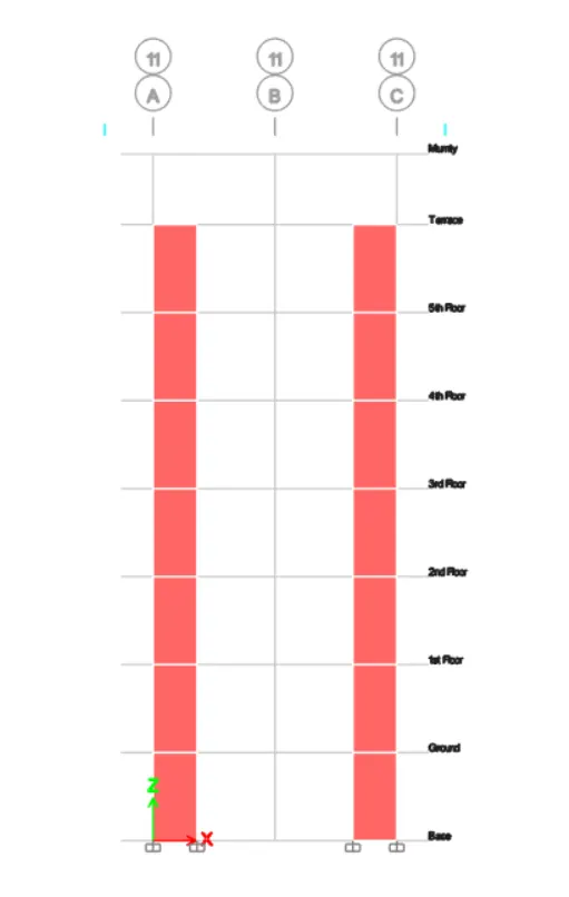
- Next the election view of grid A-11 will be visible, as shown below.
Step:-9
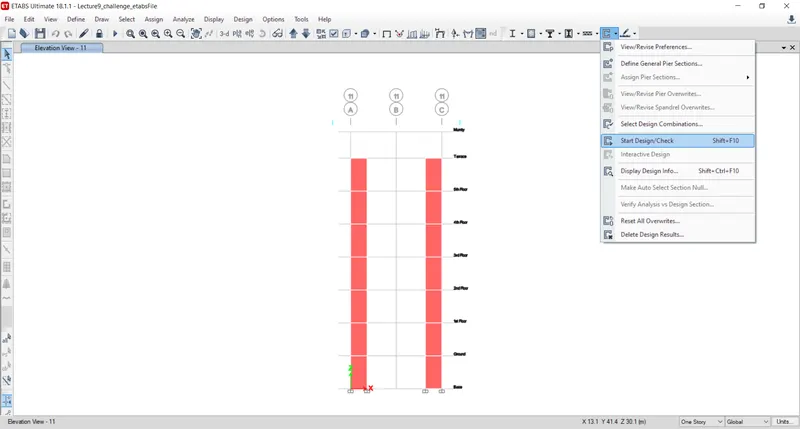
- Next we have to start the design by selecting the 'Start Design/Check' option, as shown below.
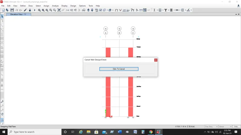
- Now we have to wait till the design completes, that will take a few seconds to complete the design.
Step:-10
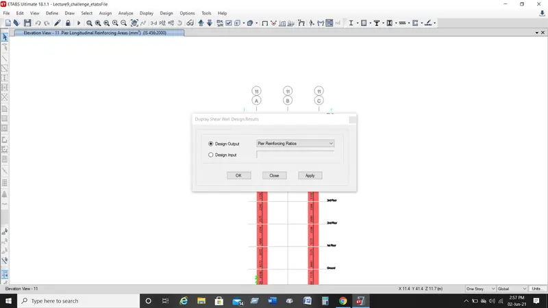
- Next we need to select the 'Display Design Info' option and then select pier reinforcement ratios in the design output and click on the ok button.
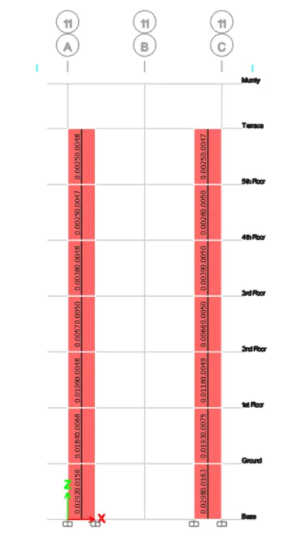
- Now the pier reinforcement ratios will be visible, as shown below.
Step:-11
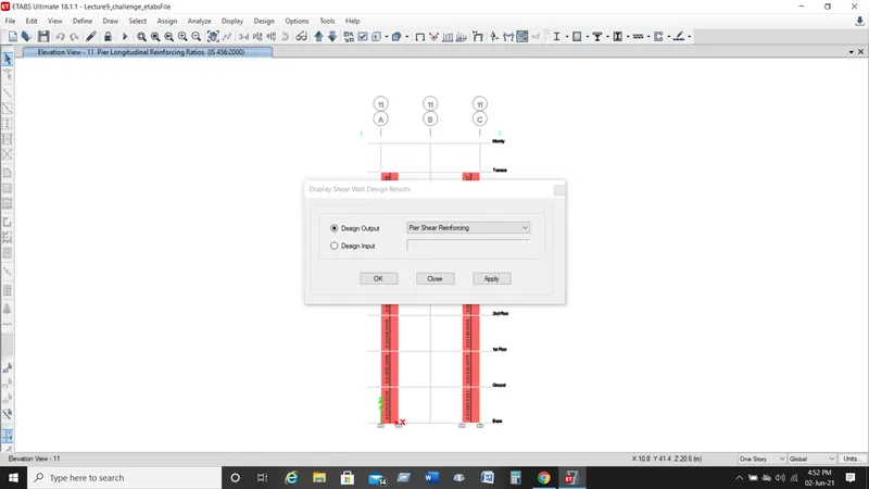
- Next again we select the 'Display Design Info' option and then select pier shear reinforcement in the design output and click on the ok button.
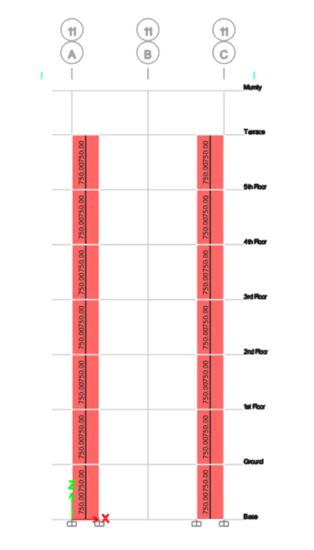
- Now the pier shear reinforcemnt details will be visible, as shown below.
Step:-12
- Select the 'Display Design Info' option and then select Pier Edges/Boundary Zones Widths in the design output and click on the ok button.
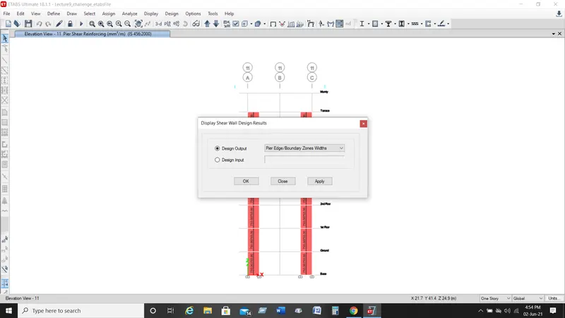
- Now the details of the boundary elements will be visible, as shown below.
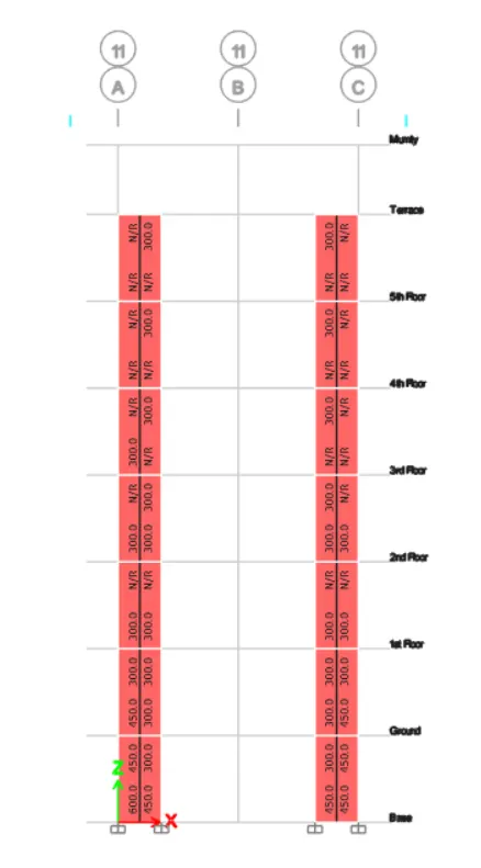
Step:-13
- Next right click on the shear wall, the design details of shear wall will be visible, as shown below.
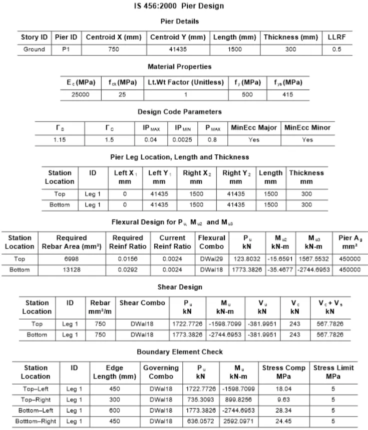
Step:-14
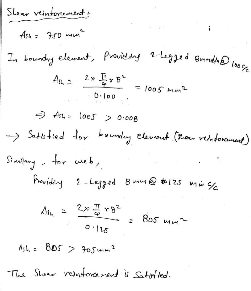
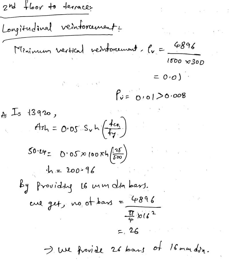
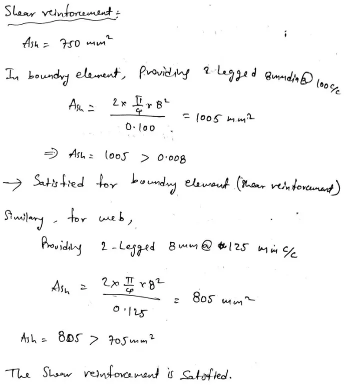
- Now we do the shear wall calculations from base up to terrace, as shown below.
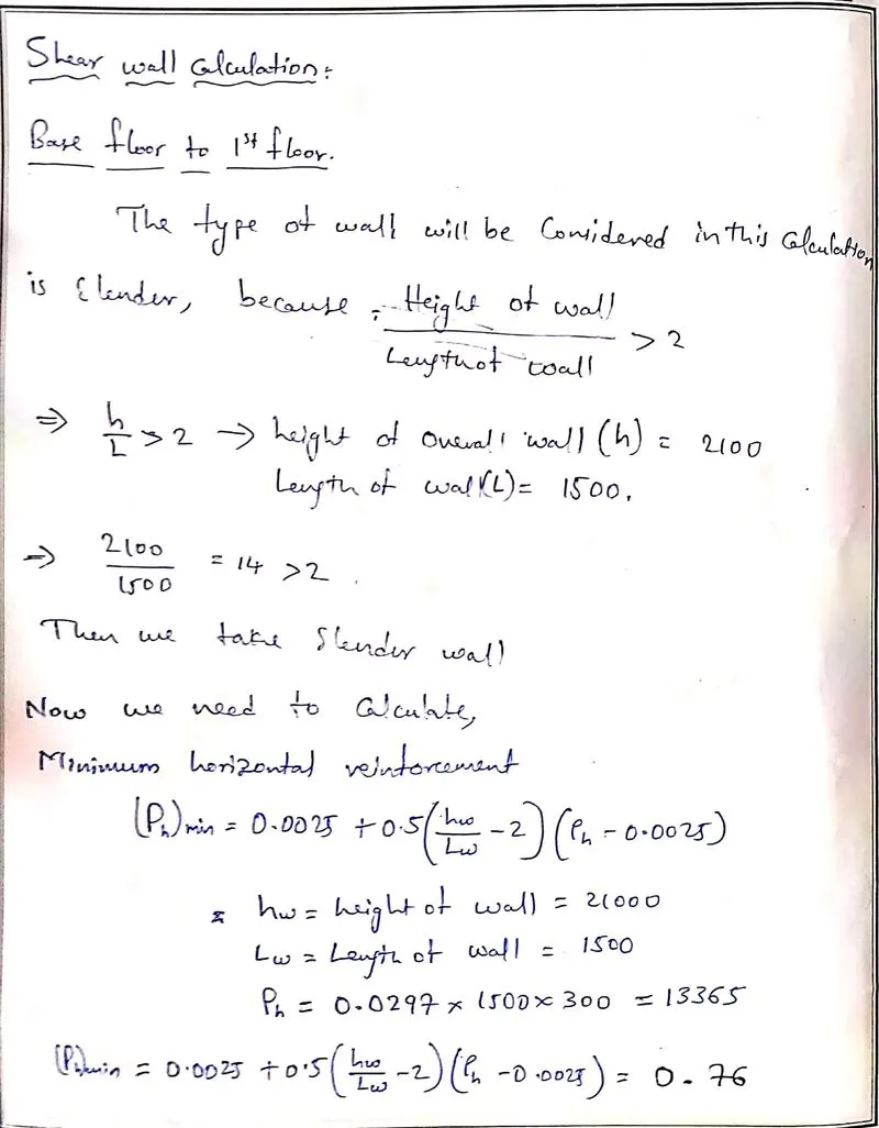
RESULT:-
- Provided the cross sectional steel arrangement of the shear wall from its base up to terrace, in compliance with provisions of IS 13920 – 2016.
- Provided the drawings of the reinforcement details of the shear wall from base up to terrace.
- Designed the RCC shear walls using the values of longitudinal steel ratio, boundary element length and shear reinforcing ratio from the etabs design results.