AutoCAD_Sketching and Editing images_Week 3
Q] Draw the following figures in detail.
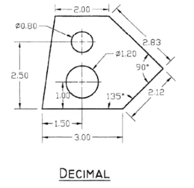
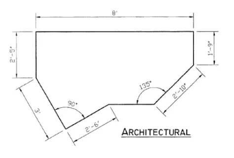
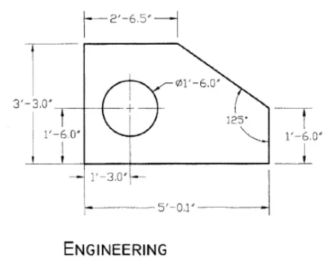
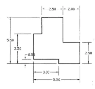
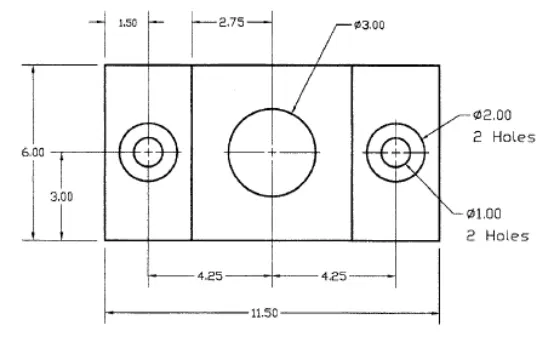
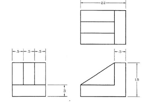
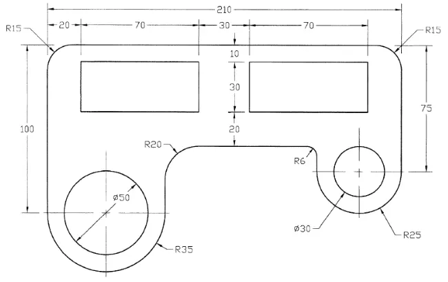
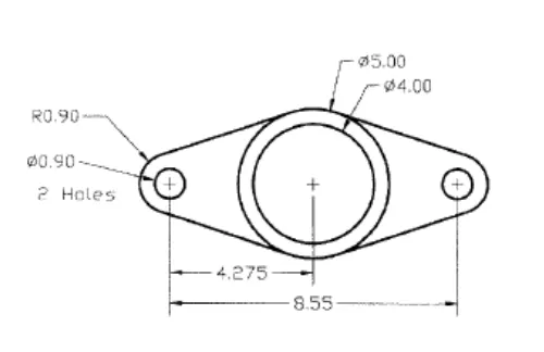
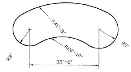
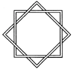
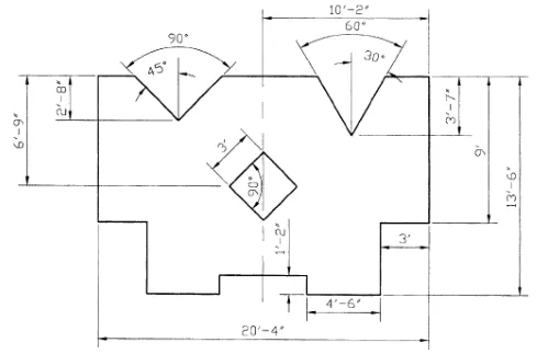
FIGURE:-1
Aim: To draw the given figure in the autocad in detail.
Commands used:
- Line command
- Circle command
- Units command
- Dimstyle command
- Dimlinear command
- Dimangular command
- Dimalign command
Procedure:
Step:-1
- First open autocad and set the units to decimal and set presicion to 0.0000 with the unit command and dimstyle command.
- First take coordinate points, next draw a line using the line command of length 3 units.
- Next take coordinates using polar coordinate system, that is (@2.12<45).
- By taking this coordinates between first line and second line we get the 135 degree angle.

Step:-2
- Next here we take the coordinates from last point of second line.
- Next take the coordinates as (@2.83<135).
- By taking this angle between the second line and third line we get 90 degrees.

Step:-3
- Next draw the line towards back from last point in step:2 of length 2 units.
- Then next joint the fourt lint to the left corner of the first line.
Step:4
- After jointing the last point to the first point then we have to create a two circles inside the figure.
- Then take first circle diameter as 0.80, and second circle diameter as 1.20.
- Put the second circle in the distance of 1 unit from 1st line to the centre of the second circle, then it will get 1 unit distance.
- Then after Put the first circle in the distance of 2.5 unit from 1st line to the centre of the first circle, then it will get 2.5 unit distance
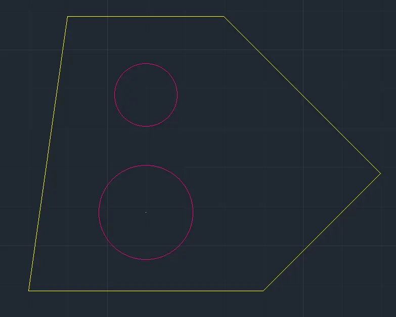
- Next put the dimentions for every part in the drawing.
Result:
- The given figure is drawn successfully in autocad.
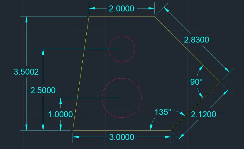
FIGURE:-2
Aim: To draw the given figure in the autocad in detail.
Commands used:
- Line command
- Units command
- Dimstyle command
- Dimlinear command
- Dimangular command
- Dimalign command
Procedure:
Step:-1
- First open autocad and set the units to architectural and set presicion to 0'-0" with the unit command and dimstyle command.
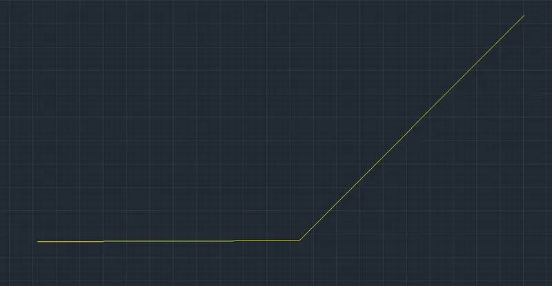
- Next come to the autocad screen, then enter the line command and draw a line of horizontally.
- Next select the line and take the coordinates for getting the angle between 1st line and second line.
- The coordinates are @2'-10"<45, by tyaking this coordinates we will get the 135 degree angle between 1st line and 2nd line.
Step:-2
- Next attach the another line by drawing line using the line command of length 8'.

Step:-3
- Next draw the line downwards from the last point of the third line, and the length is 2'-5".
- Next draw the line using the polar coordinate system, because of getting the 90 degrees angle between the fifth line and sixth line.
- The coordimnates we take are @3'<300, and attach the fifth line last point to the first line of left point.
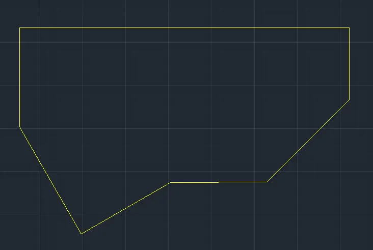
- Next put the dimentions for every part in the drawing.
Result:
- The given figure is drawn successfully in autocad.
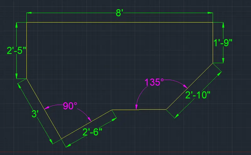
FIGURE:-3
Aim: To draw the given figure in the autocad in detail.
Commands used:
- Line command
- Units command
- Circle command
- Dimstyle command
- Dimlinear command
- Dimangular command
- Dimaligned command
Procedure:
Step:1
- First open autocad and set the units to engineering and set presicion to 0'-0.0" with the unit command and dimstyle command.
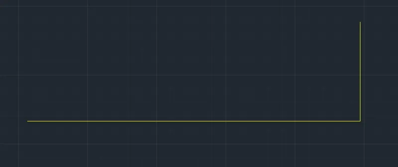
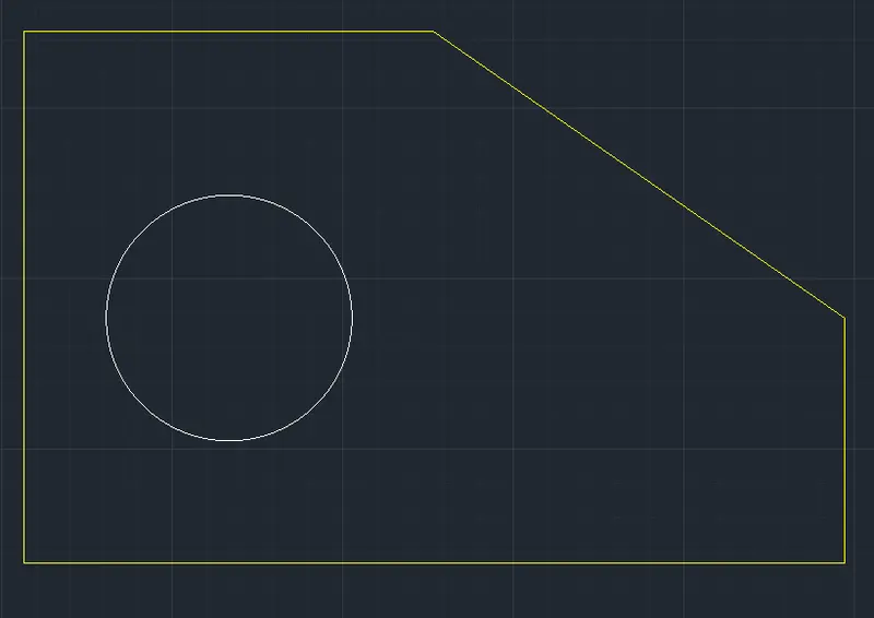
- Next turn on the ortho mode and enter line command and draw a line of length 1'-6.0".
- Next draw a line with line command of length 5'-0.1" from the last point of 1st line.
Step:-2
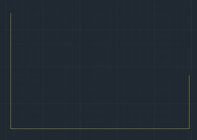
- Next draw a line from the last point of the second line with the length of 3'-3.0".
- By drawing the staight line use ortho mode, turn on the ortho mode.
- If there is inclined line then turn off the orthomode and draw the line.
Step:-3
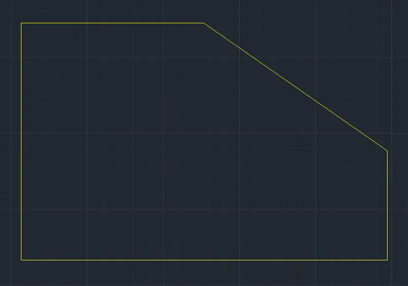
- Draw a line from the last point of third line of length of 2'-6.0".
- Next draw the line using the polar coordinate system, and attach the fifth line to the first point of the first line.
- The coordinates are @3'<0.7" and attach the first point of first line.
- And we get the angle 125 degrees using the polar coordiante system.
Step:-4
- Next we have to create the circle inside at the centre in the figure.
- The using the coordinate lengths we get the circle centre in the figure.
- The coorinates given are (1'-3.0",1'-6.0").
- By using this coorinate points we draw circle with reference to this coordinates.
- Next put the dimentions for every part in the drawing.
Result:
- The given figure is drawn successfully in autocad.
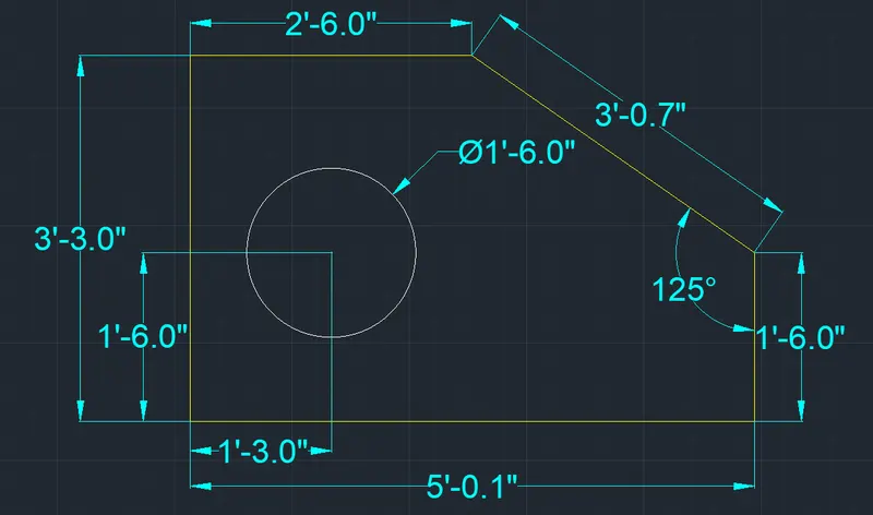
FIGURE:-4
Aim: To draw the given figure in the autocad in detail.
Commands used:
- Line command
- Units command
- Dimstyle command
- Dimlinear command
Procedure:
Step:-1
- First open autocad and set the units to decimal and set presicion to 0.0000 with the unit command and dimstyle command.
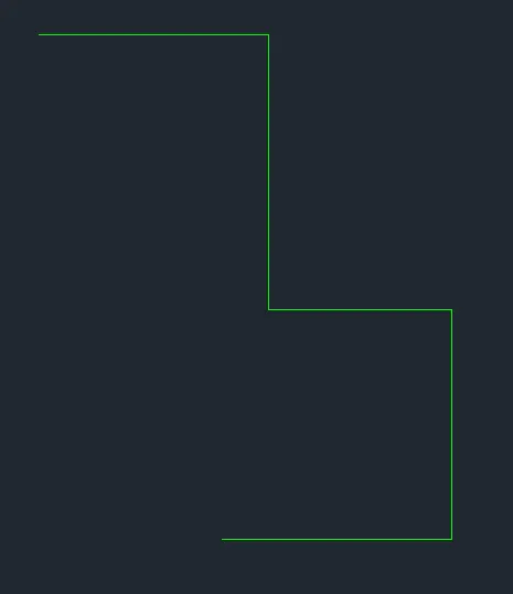
- First draw the line using the line command of length 2.500 units
- Next attach a line to the previous point and draw line upwards and the length is 2.500 units.
- next draw aline from the prvious point of length 2.0000 units.

Step:-2
- Next draw the another line attached with the previous point of third line, with the length of 3.000 units
- Next draw the another line attached with the fourth line of the length 2.5000 units.
Step:-3
- Now we draw line downwards from the previous point with the length of 2.0000 units.
- Next draw the line attached with the previous point and length of line is 1.0000 units
- In th similar ways draw the line downwards with the length of 3.0000 units.
- Next continue to another line with the length towards the first line is 3.0000 units.
- next join the last point of last line and first point of first line.
- By joining this we get the given figure shown below.
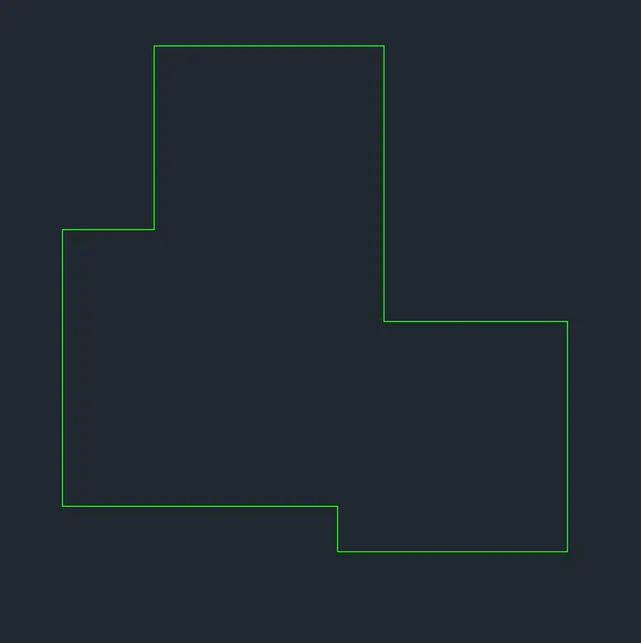
- Next put the dimentions for every part in the drawing.
Result:
- The given figure is drawn successfully in autocad.
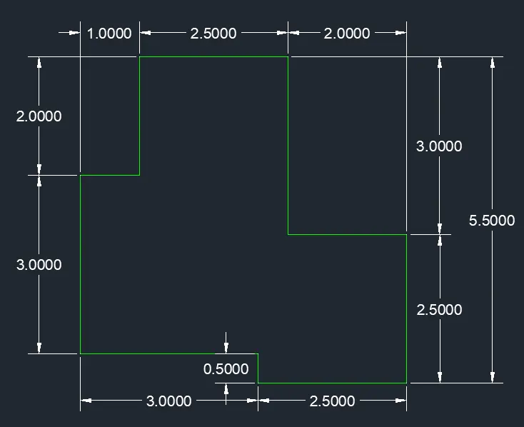
FIGURE:5
Aim: To draw the given figure in the autocad in detail.
Commands used:
- Rectangle command
- Line command
- Units command
- Circle command
- Dimstyle command
- Dimlinear command
Procedure:
Step:-1
- First open autocad and set the units to decimal and set presicion to 0.0000 with the unit command and dimstyle command.
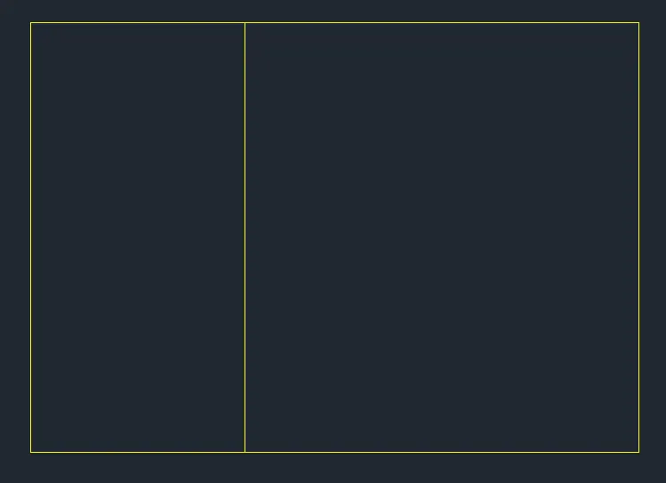
- First type the rectangle command in command box, then select the dimentions, then give the dimentions as length is 3.0000 and width is 6.0000 units.
- By taking this dimensions we get the rectangular shape in the autocad screen.
Step:-2
- Now draw a line from the top right corner of the rectangle, the length is 5.5000 units.
- Next draw a line downwards with the length of 6.0000 units.
- Next draw the line towards the last corner of the rectangle and attach to it, the the length of the line is 5.5000 units.
Step:3
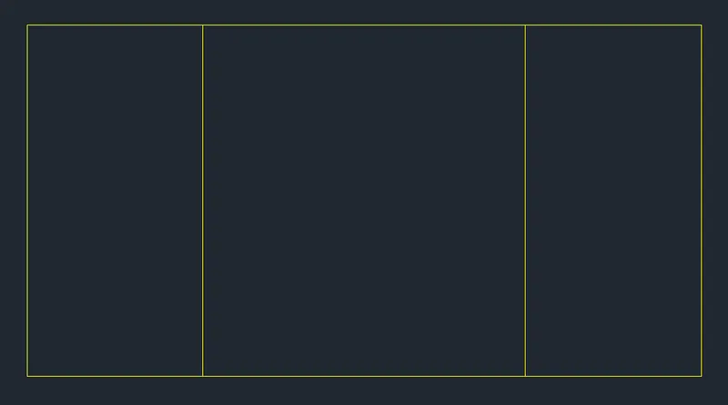
- Now draw a line from the previous point from the top corner, the length is 5.5000 units.
- Next draw a line downwards with the length of 6.0000 units.
- Next draw the line towards the last point from the previous point and attach to it, then the length of the line is 5.5000 units.
Step:-4
- First draw the circle in the first rectangle in the centre of the rectangle with the diameter of 1 unit
- And then again draw the circle in same rectangle and take the diameter as 2 unit.
- Next draw the circle in the middle of the second rectangle with the diameter of 3 units.
- Next draw the circle in the third rectangle in the centre of the rectangle with the diameter of 1 unit
- And then again draw the circle in same rectangle and take the diameter as 2 unit
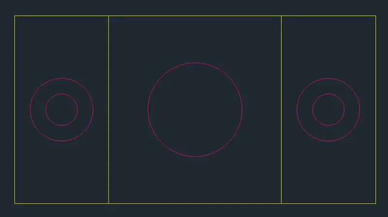
- Next put the dimentions for every part in the drawing.
Result:
- The given figure is drawn successfully in autocad.
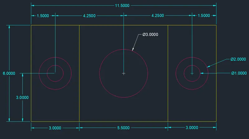
FIGURE:6
Aim: To draw the given figure in the autocad in detail.
Commands used:
- Line command
- Units command
- Dimstyle command
- Dimlinear command
Procedure:
Step:-1
- First open autocad and set the units to decimal and set presicion to 0.0000 with the unit command and dimstyle command.
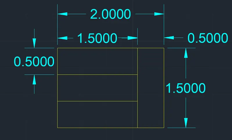
- First draw a line of length 2.0000 units.
- Next draw a line down wards from the previous point of length 1.5000 units.
- Next again draw the line left side from the previous point with the length of 2.0000 units.
- Next join the last point to the first point that is the length of 1.5000 units.
- Next draw the line at the distance of 0.5000 units from the left side to the other side of length 1.5000.
- And continue this with one more time.
Step:-2
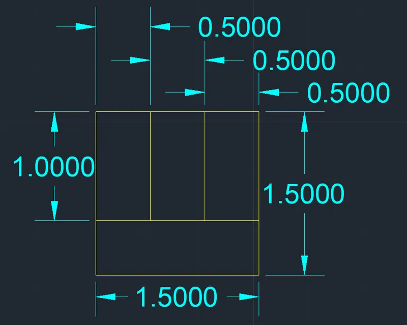
- First draw a line of length 1.5000 units.
- Next draw a line left side from the previous point of length 1.5000 units.
- Next again draw the line upwards from the previous point with the length of 1.5000 units.
- Next join the last point to the first point that is the length of 1.5000 units.
- Next draw the line at the distance of 0.5000 units from the left side corner, And continue this with one more time.
Step:-3
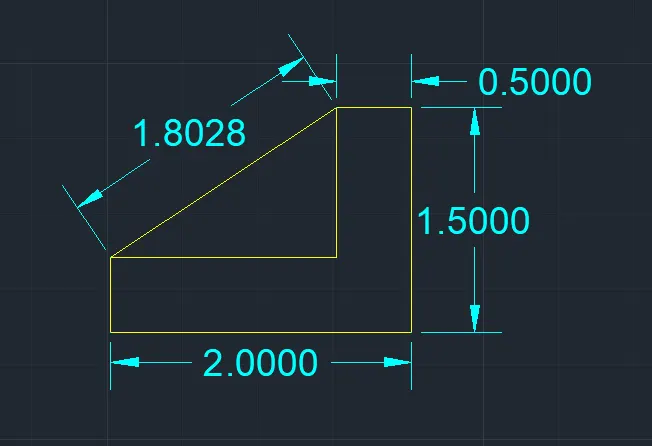
- Here we draw the line with the line command with the length of 1.5000 units to downwords.
- Next draw the line towards back with the length of 2.000 units.
- Next draw line upwards with the length of 0.5000.
- Next draw the line towards the length of 1.5000.
- Nextd draw the line upwards with line command of length 1.0000 units
- Finally join the last point and first point at the top.
- Next join the line towards back with the angle of 225 degrees, or join the two end points, that are shown in figure below.
- Next put the dimentions for every part in the drawing.
Result:
- The given figures are drawn successfully in autocad.
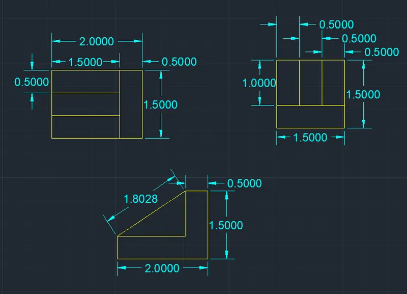
FIGURE:-7
Aim: To draw the given figure in the autocad in detail.
Commands used:
- Line command
- Fillet command
- Rectangle command
- Units command
- Circle command
- Dimstyle command
- Dimlinear command
- Dimaligned command
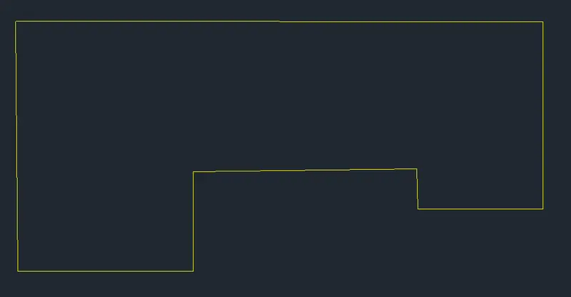
Procedure:
Step:-1
- First open autocad and set the units to decimal and set presicion to 0.0000 with the unit command and dimstyle command.
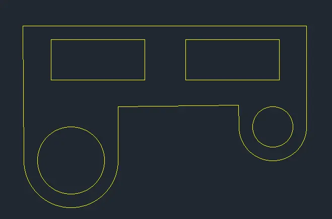
- First draw the line using the line command towards the length of 210.0000 units in the top.
- Next draw the line downwards with the lrngth of 75.0000 units from the previous point.
- Next draw the line towards back with length of 50.0000 units from the previous point.
- Then next draw the upwards from the last line with the length of 15.0000 units.
- Next draw the line towards back with the length of 90.0000 units.
- Next draw the line downwards with the length of 40.0000 units from the previous point.
- Next draw the line backwards with the length of 70.0000 units from the last point of previous one.
- Then join the 1st line and last line then the figure will be closed.
Step:-2
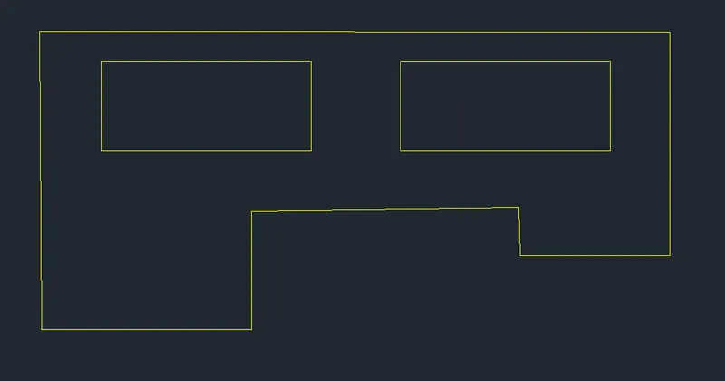
- After joining al the lines, we have to create the rectangles inside the figure.
- The rectangle is created at a distance of 10.0000 units at the top.
- The second rectangle is placed with a distance of 30.0000 units from the first rectangle.
Step:-3
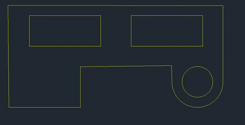
- Next use the fillet commant to create the arch between two lines.
- Enter the fillet command in command box and select radius, then select the two lines to form arc with radius 25.0000 units at right side of the figure
- Then use the circle command and draw with the diameter of 30.0000 units.
Step:-4
- Next use the fillet commant to create the arch between two lines.
- Enter the fillet command in command box and select radius, then select the two lines to form arc with radius 35.0000 units at left side of the figure
- Then use the circle command and draw with the diameter of 50.0000 units, at the left side of the figure.
- Next put the dimentions for every part in the drawing.
Result:
- The given figures are drawn successfully in autocad.
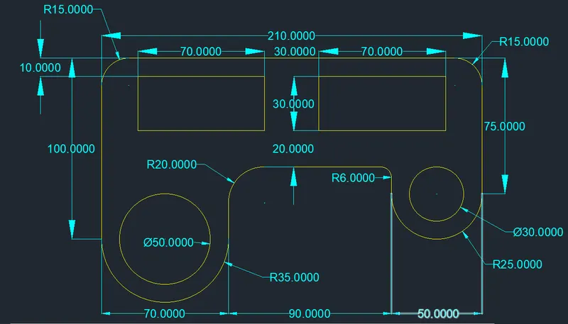
FIGURE:-8
Aim: To draw the given figure in the autocad in detail.
Commands used:
- Line command
- Fillet command
- Units command
- Circle command
- Trim command
- Dimstyle command
- Dimlinear command
- Dimaligned command
Procedure:
Step:-1
- First open autocad and set the units to decimal and set presicion to 0.0000 with the unit command and dimstyle command.
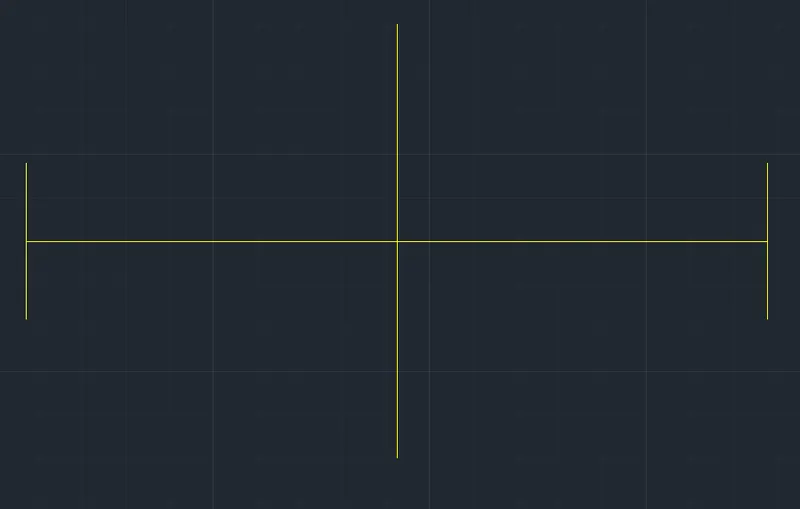
- First draw the line using the line command with the length of 8.5500 units.
- Next from left side draw the line vertically with the length of 1.8000 units at the centre to the horizontal line.
- Similarly from the right side draw the line vertically with the length of 1.8000 units at the centre to the horizontal line.
Step:-2
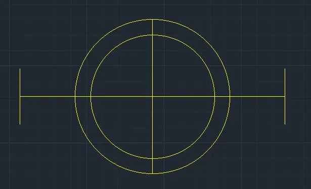
- Next draw the circle at centre of the horizontal line with the diameter of 4.0000 units.
- Again draw the circle at centre of horizontal line with the diameter of 5.0000 units.
Step:-3
- Now draw a line from end points to the top of the circle.
- This is Similar to the all ends to draw a line to the top of the circle.
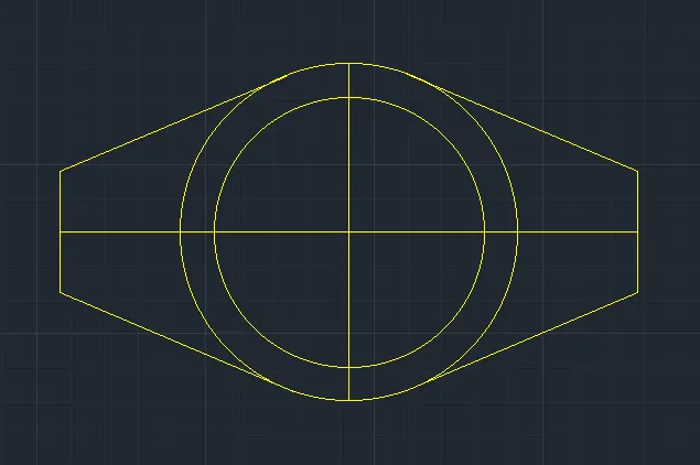
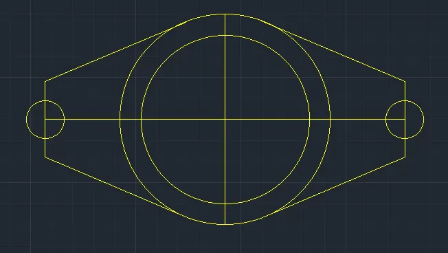
Step:4
- Now draw the circles at left and right sides of the both ends to the centre of horizontal line.
- Draw the circles of diameter 0.9000 units both left end and right end.
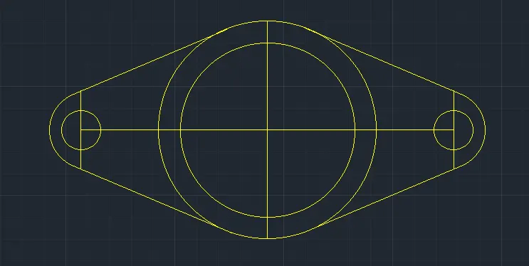
Step:-5
- Now use the fillet command to join the two lines with arc.
- Then select the fillet command in command box and select lines to form the arc between two lines.
- Then the radius of arc is 0.9000 units, at the both ends.
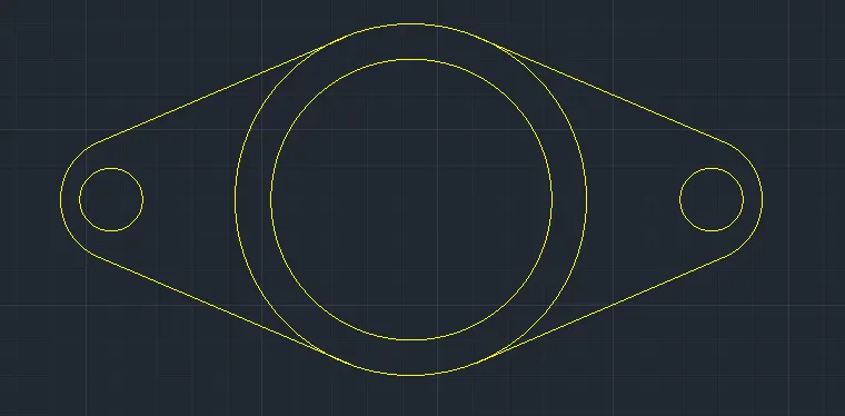
Step:6
- Finally use the trim command to remove unwanted lines.
- And then we drawn the given figure.
- Next put the dimentions for every part in the drawing.
Result:
- The given figure is drawn successfully in autocad.
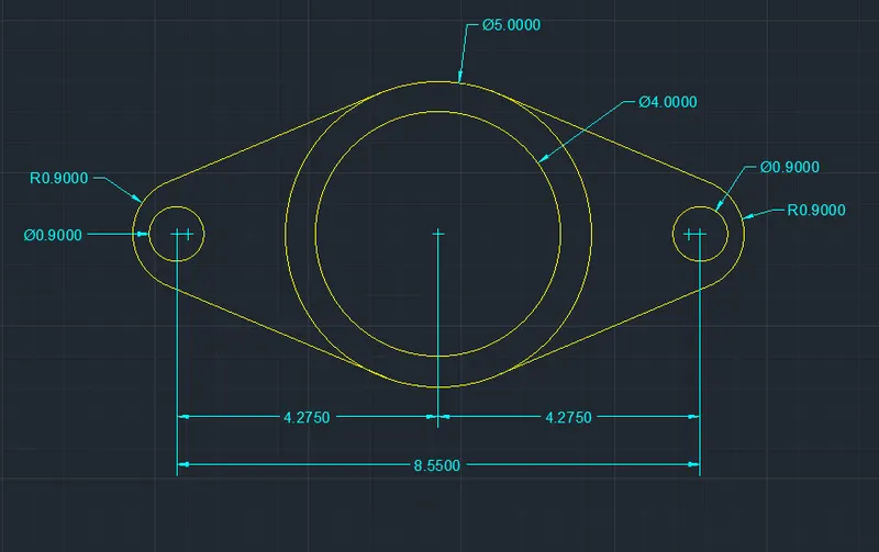
FIGURE:-9
Aim: To draw the given figure in the autocad in detail.
Commands used:
- Line command
- Arc command
- Units command
- Circle command
- Trim command
- Dimstyle command
- Dimlinear command
Procedure:
Step:-1
- First open autocad and set the units to architectural and set presicion to 0'.0" with the unit command and dimstyle command.
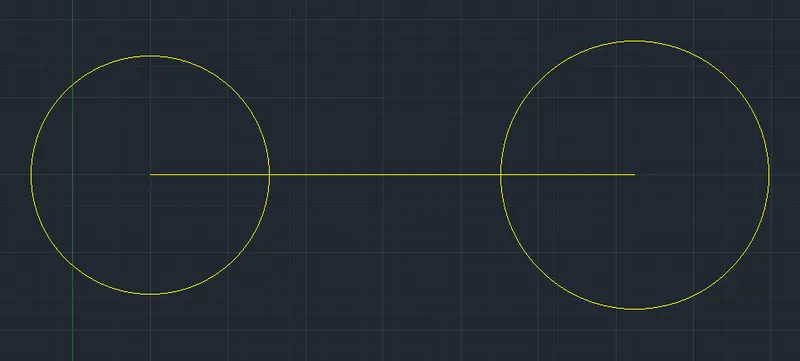
- First draw a line using the line command with the length of 32'-6".
- Then draw a circles for both left end and right end of the line.
- The Radius of left side circle is 8' and the radius of right side circle is 9'.
Step:-2
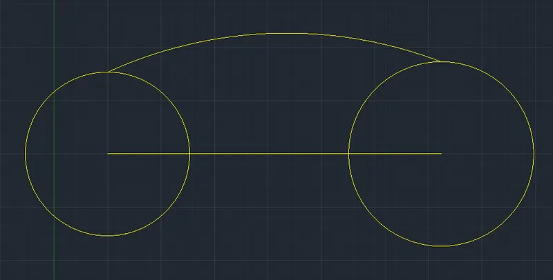
- Next use the arch(start,end,radius) from top of the first circle to the top of the second circle.
- After entering the arc at top with the radius of 41'-8" will be displayed, that is shown in below figure.
Step:-3
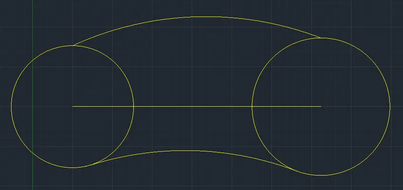
- Again we have to use the arc(start,end,radius) command to create the arc between the first circle and the second circle.
- After entering the arc command at bottom with the radius of 20'-10" will be displayed, that is shown in below figure.
Step:4
- Now we use the trim command to trim the unwanted things in the drawing.
- And then we drawn the given figure shown below.
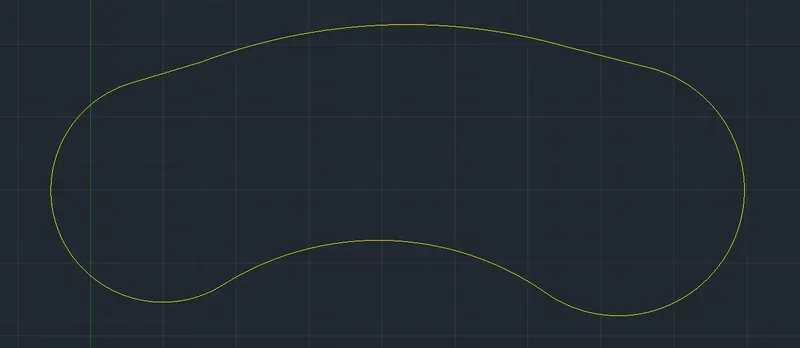
- Next put the dimentions for every part in the drawing.
Result:
- The given figure is drawn successfully in autocad.
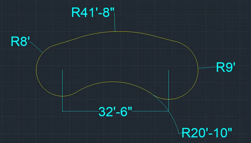
FIGURE:-10
Aim: To draw the given figure in the autocad in detail.
Commands used:
- Rectangle command
- offset command
- Rotate command
- Units command
- Dimstyle command
- Dimlinear command
Procedure:
Step:-1
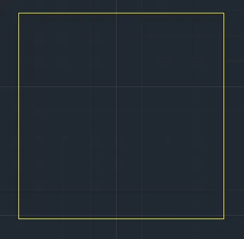
- First we have to enter the rectangle command in the command box, and select the dimensions option after entering the rectangle command.
- Then after selecting the dimensions, then give the dimensions, the length is 3.0000 units and width is 3.0000 units.
- The dimensions are not given, but i assumed the dimensions.
Step:2
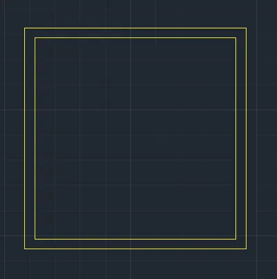
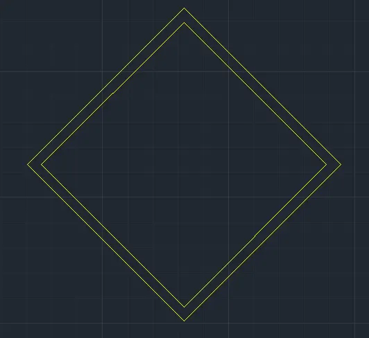
- Then we use the offset command to offset the rectangle.
- Take any value as offset value, then do the offset.
- Then the figure is shown below to understand.
Step:-3
- Here we use the rotate command to rotate it.
- Then we rotate it to the inclined angle(45 degrees) using the rotate command.
Step:-4
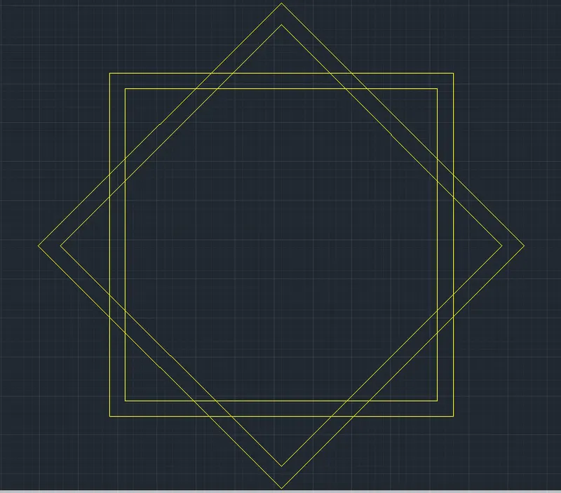
- The rotated offsetted rectangle has been placed on the non-rotated rectangle.
- And trim the unwanted lines in the drawing.
- Then it will be look like the figure shown below.
Result:
- The given figure is drawn successfully in autocad.
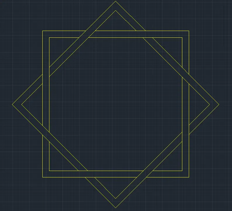
FIGURE:-11
Aim: To draw the given figure in the autocad in detail.
Commands used:
- Line command
- Units command
- Dimstyle command
- Dimlinear command
- Dimaligned command
- Trim command
- Rotate command
Procedure:
Step:-1
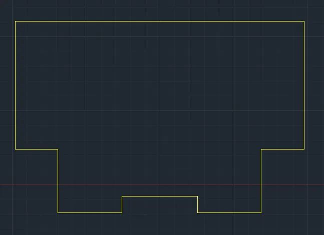
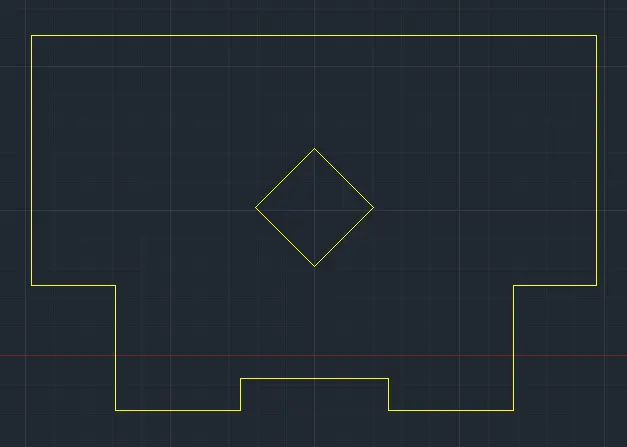
- Now we draw the line using line command with the length of 1'-2" downwards.
- Next draw line forward with the length of 4'-6" from the previous line.
- Next draw the line upwards with the length of 4'-6" from the previous line.
- Now we draw the line using line command with the length of 3' forward.
- Draw line upwards with the length of 9' from the previous line.
- Next draw the line towards back with the length of 20'-4" from the previous line.
- Now we draw the line using line command with the length of 6'-9" downwards.
- Draw line forward with the length of 3' from the previous line.
- Next draw the line downwards with the length of 4'-6" from the previous line.
- Now we draw the line using line command with the length of 4'-6" forwards.
- Next draw the line upwards with the length of 1'-2" from the previous line.
- Next join the first point of first line and last point of last line.
- Hence we drawn the given figure.
Step:-2
- First we draw the rectangle separately with the dimensions of length 3' and width 3'.
- Now locate the center of the object and place the rectangle at the centre of the object.
- Next we rotate the rectangle to the 45 degrees.
Step:-3
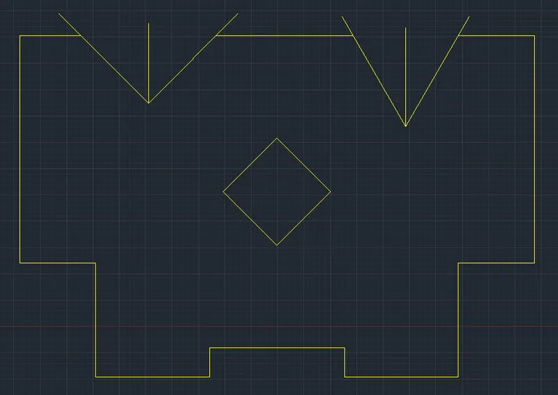
- Now we place the angles at the top of the object, then we place the angle 45 degrees and 90 degrees at a distance of 5'-1" from the left side of the object at the top.
- And another angles 30 degrees and 60 degrees were placed at a distance of 5'-1" from the right side of the object at the top.
- Then it will be look like the figure shown below.
- Next put the dimentions for every part in the drawing.
Result:
- The given figure is drawn successfully in autocad.
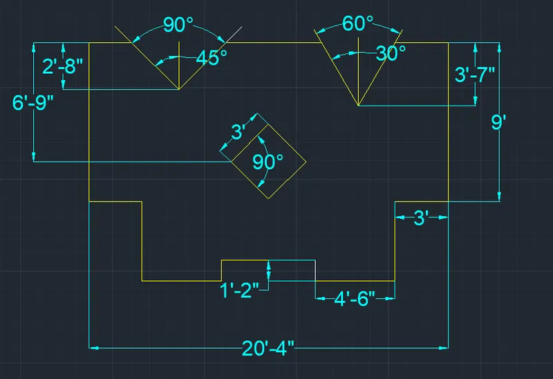
Final Result:-
- The given figures are drawn succesfully in autocad in the detailed manner.