Analysis & Design of RCC shear walls in the model using ETABS
The etabs file for a G+6 building is provided. Run the analysis and design the RCC shear walls (show in the etabs model). The following challenge deals specifically with the shear wall of size 300x1500 at grid A-11 in the structural model.
- Extract values of longitudinal steel ratio, boundary element length and shear reinforcing ratio from the design results.
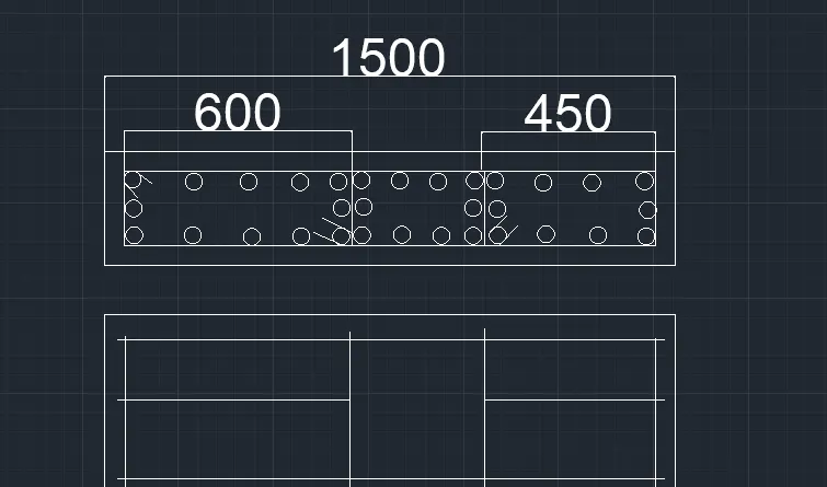
- Provide cross sectional steel arrangement of the shear wall from its base up to terrace, in compliance with provisions of IS 13920 – 2016. AutoCAD application can be used for this exercise. Alternatively, it can be drawn by hand as well.
- Provide elevation drawings of the reinforcement details of the shear wall from base up to terrace.
AIM :
To Using The etabs file for a G+6 building is provided. Run the analysis and design the RCC shear walls (show in the etabs model). The following challenge deals specifically with the shear wall of size 300x1500 at grid A-11 in the structural model.
INTRODUCTION :
Shear wall is a structural member used to resist lateral forces, that is, parallel to the plane of the wall. For slender walls where the flexural deformation is more, shear wall resists the loads due to cantilever action. In other words, shear walls are vertical elements of the horizontal force resisting system.
PROCEDURE :
STEP 1;
- Download the given etabs model , and open it an etab file.
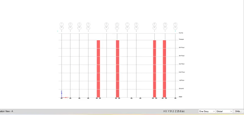
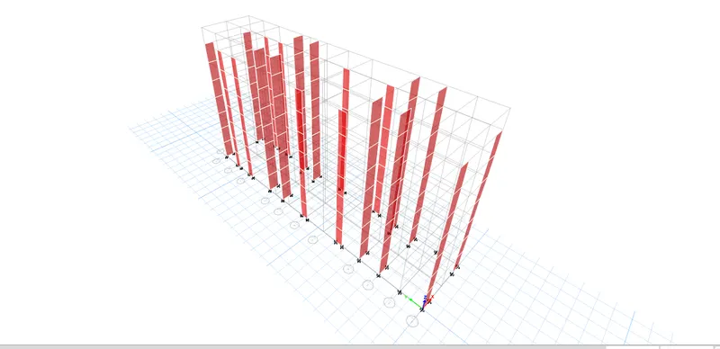
- set all stories in the bottom right corner
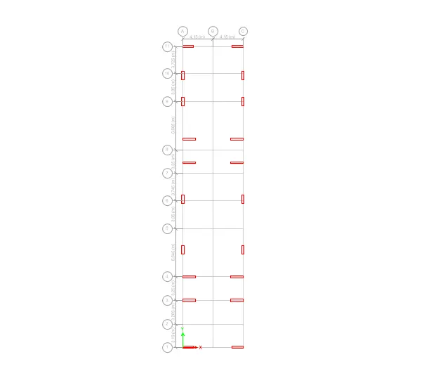
- select 11A wall and go to right click and click the selected objects only,
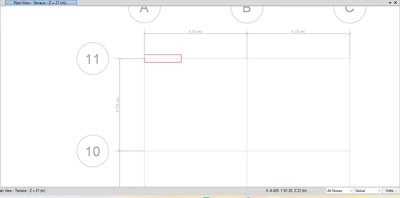
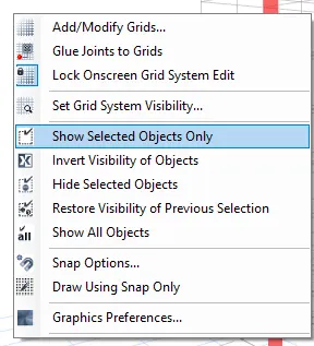
- selected objected image as shown below ,
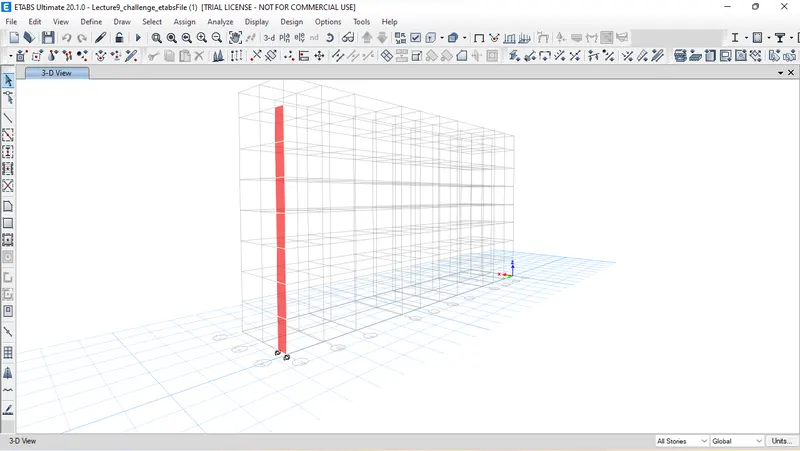
STEP 2;
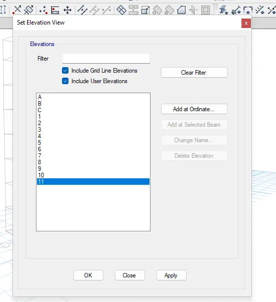
- Go to the elevation option on top tool bar,
- set elevation view dialogue as been opened,
- select the elevation 11 and apply
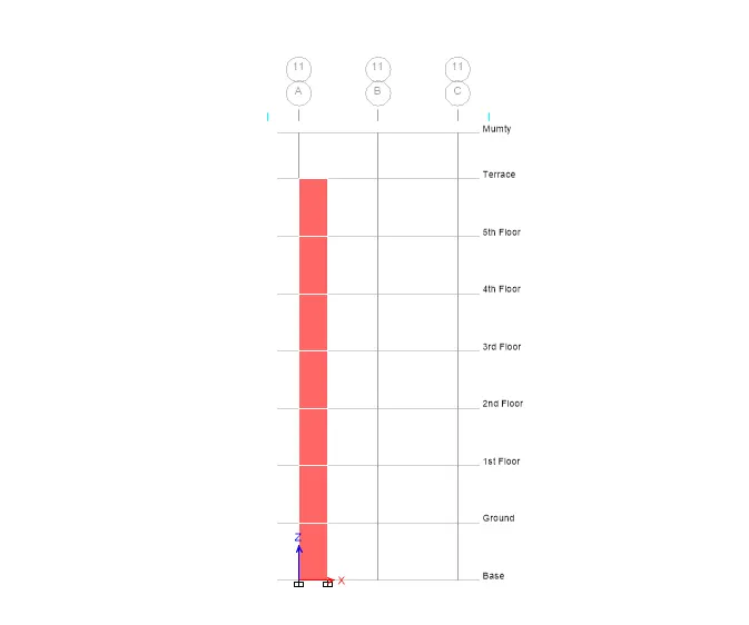
STEP 3;
- Go to the set display option,
- select the label and then apply,
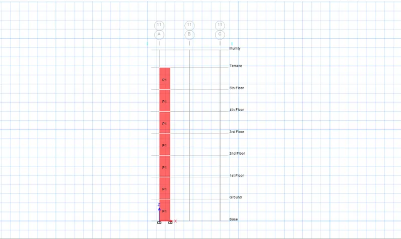
- then check the label option as viewed or not
- they has been viewd like as P1
- then again go to set display option unselect the label and apply,
STEP 4;
- click Run analysis option
- after analysis, click the shear wall design option
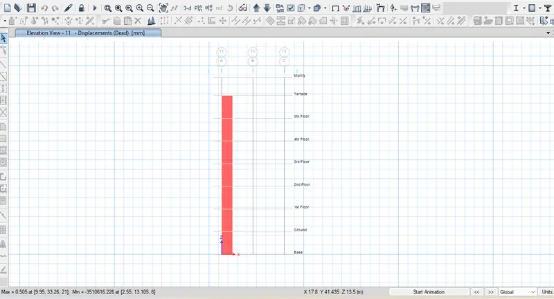
- the model has been designed checked
- the values of shear wall has been shown,
STEP 5;
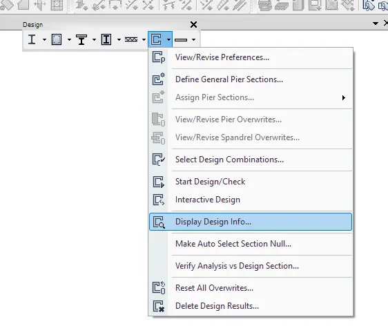
- Again go to shear wall design option, pick the design display info
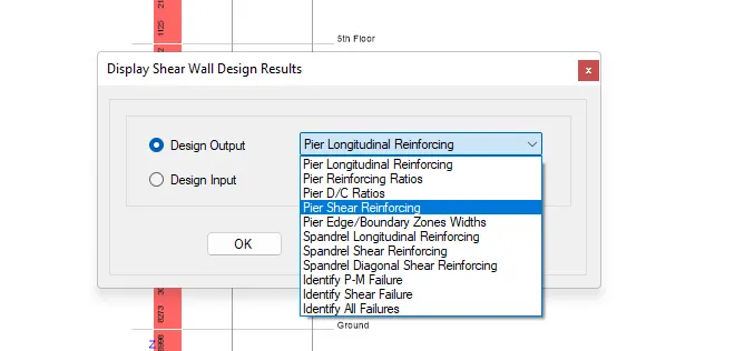
- display the shear wall result.
- pick the pier shear reinforcing,

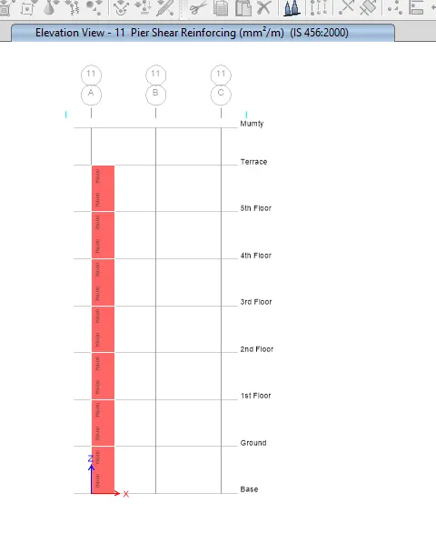
- after selecting pier shear reinforcing , the values has been shown in the shear wall
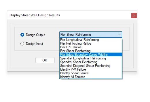
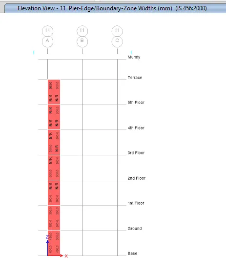
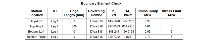
- next we want to pick the boundary zone walls and the values are shown in the shear walls,
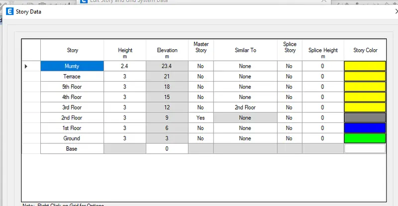
- go to edit grid story and screen shot it,
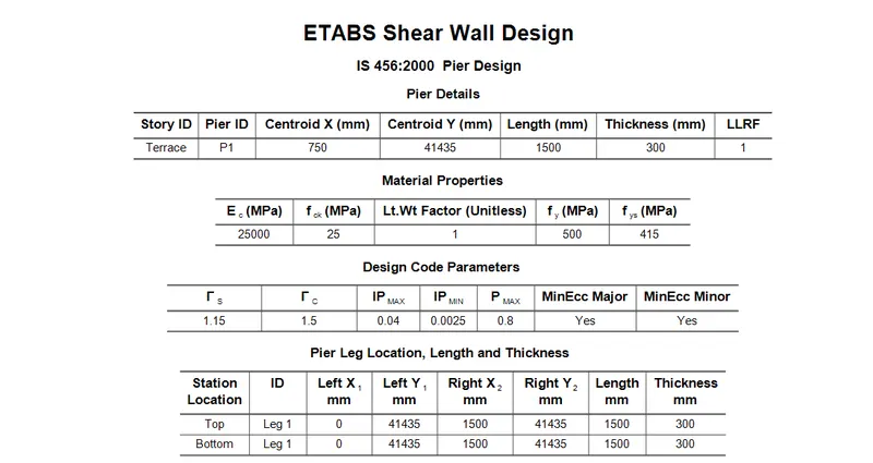
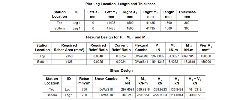
- right click the shear and go to shear wall details, and check the details
STEP 7;
- Using auto cad sofware to draft the reinforcement details,
STEP 8;
CALCULATION,
As per IS13920-2016
- Over all height of the wall h = 21000mm , Length of the wall L = 1500 mm
- Ratio (h/L) = 21000/1500 = 14>2, The given Rc wall is slender
2. The largest diameter can be used in rc shear wall should not exceed 1/10th of thickness of wall
so 300/10 = 30mm
- we used 25mm dia bar rebar in the detailing hence ok,
3. The maximum spacing of longitudinal / transverse rebar should not exceed
- 1/5th of horizontal length (l) 1500/5 = 300mm
- 3 times of thickness = 3 * 300 900mm
- 450mm
- so we have to adopt maximum 300mm spacing both for vertical and horizontal rebar inside rc wall
4. Minimum horizontal reinforcement calculation as per table 1 IS13920-2016
- ph min'>ph min = 0.0025 + 0.5
- (hwLw-2)(ph-0.0025) > (hwLw-2)(pn-0.0025) = 0.01672 of cross section of Rc wall
- 1500*300*0.01672 = 7524sqmm
- 7524/21 = 358 sqmm
- we already provided 16mm dia at 100mm c/c spacing .
5. Minimum boundary reinforcement calculation as per table 1 IS13920-2016
- 0.008 *300*300 = 720sqmm
- we already provided minimum 8 numbers 12mm dia rebar = 8 * 113 = 904sq.mmm
- Hence ok
6. Minimum web reinforcement calculation as per table 1 IS13920-2016
- 0.0025 *900*300 = 675 sqmm
- we already provided minimum 8 numbers 12mm dia rebar = 8 * 113 = 904sq.mmm
- Hence ok
7. Minimum Overall Rc wall vertical reinforcement calculation as per table 1 IS13920-2016
- 0.0025 + 0.01375 = 0.00525 (times of wall cross section)
- 0.00525*1500*300 = 2363 sq .mmm
- we already provided minimum 24 numbers 12mm dia rebar = 24 * 113 = 2712sq.mmm
- Hence ok
8. Boundary element special confining reinforcement as per clause 10.4.4 of IS13920-2016
- Ash =0.05vh (fckfy) > Ash = 0.05syh (fakfy)
- maximum spacing of confinment is 100mm spacing as per drawing
- h = minimum clear distance between longitudinal rebar = 150mm say
- Ash > Ash = 45sq.mm
- we already provided two closed links of 16mm dia 2*201 = 402 sq.mm
- Hence ok
RESULT :
Thus we have specified the designed Rc wall and detailed using auto cad sofware , also the clauses gfrom ductility code IS13920-2016 are verified for Rc wall detailing .