Analysis & Design of RCC shear walls in the model using ETABS
AIM-
- To extract values of longitudinal steel ratio, boundary elements length and shear reinforcement from design results.
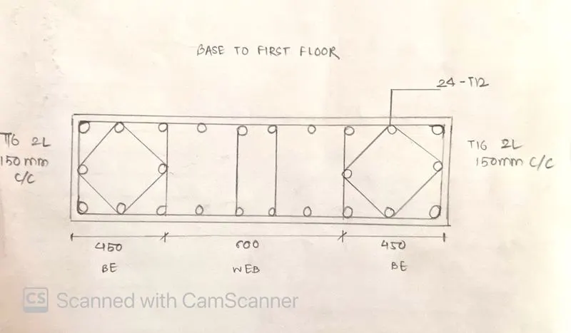
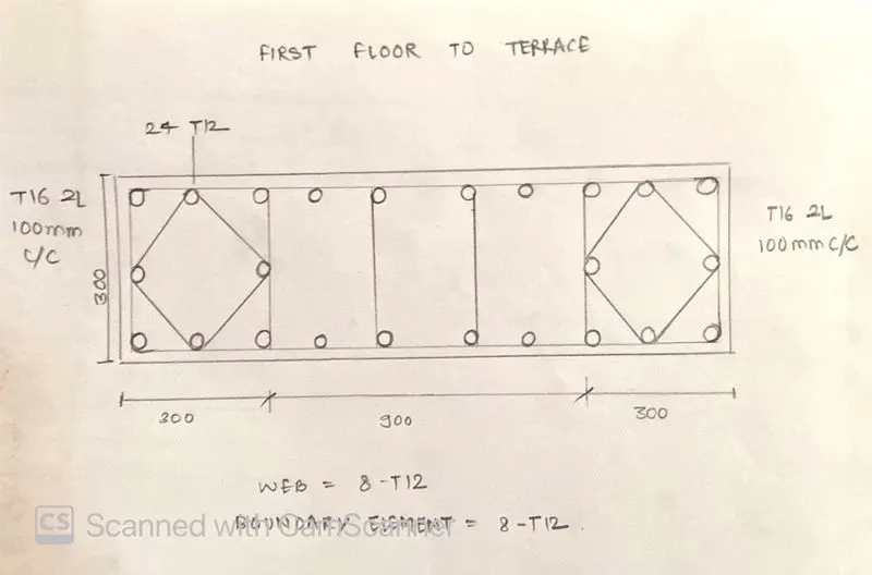
- To provide cross section steel arrangement from base to terrace w.r.t IS 13920-2016.
- To provide elevation drawings of reinforcement details of shear walls from base to terrace.
PROCEDURE -
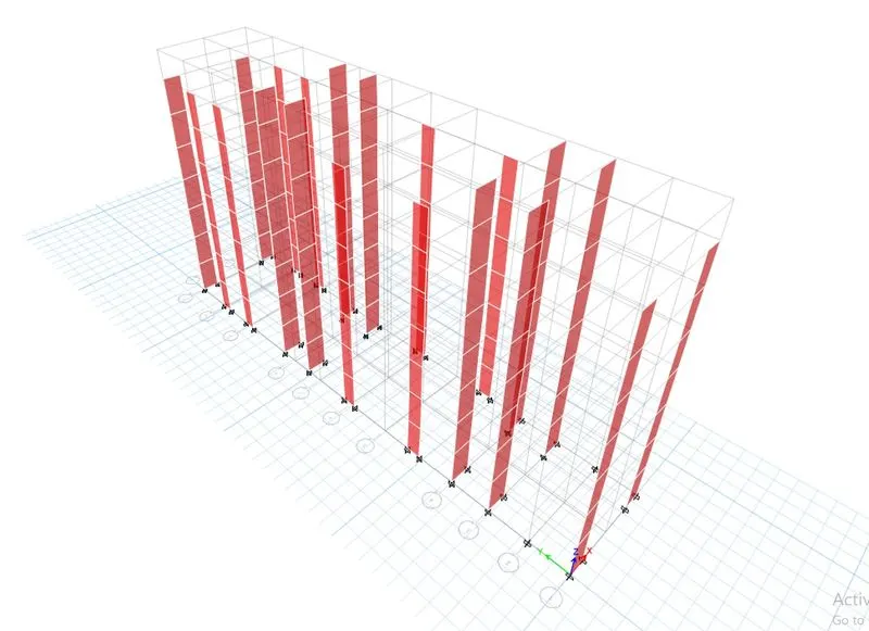
1. Open the given ETABS file and Run Analysis :
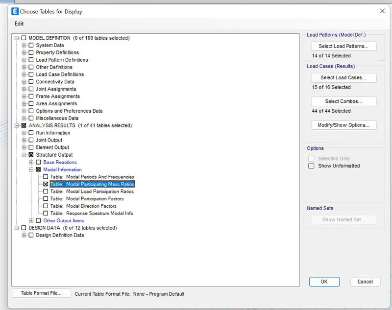
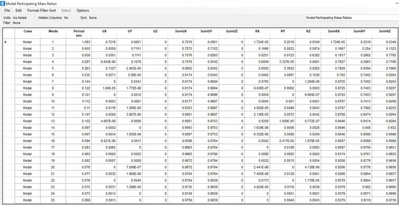
2. Display > Show tables > Structure output > Modal Info > Modal Participating Mass Ratios :
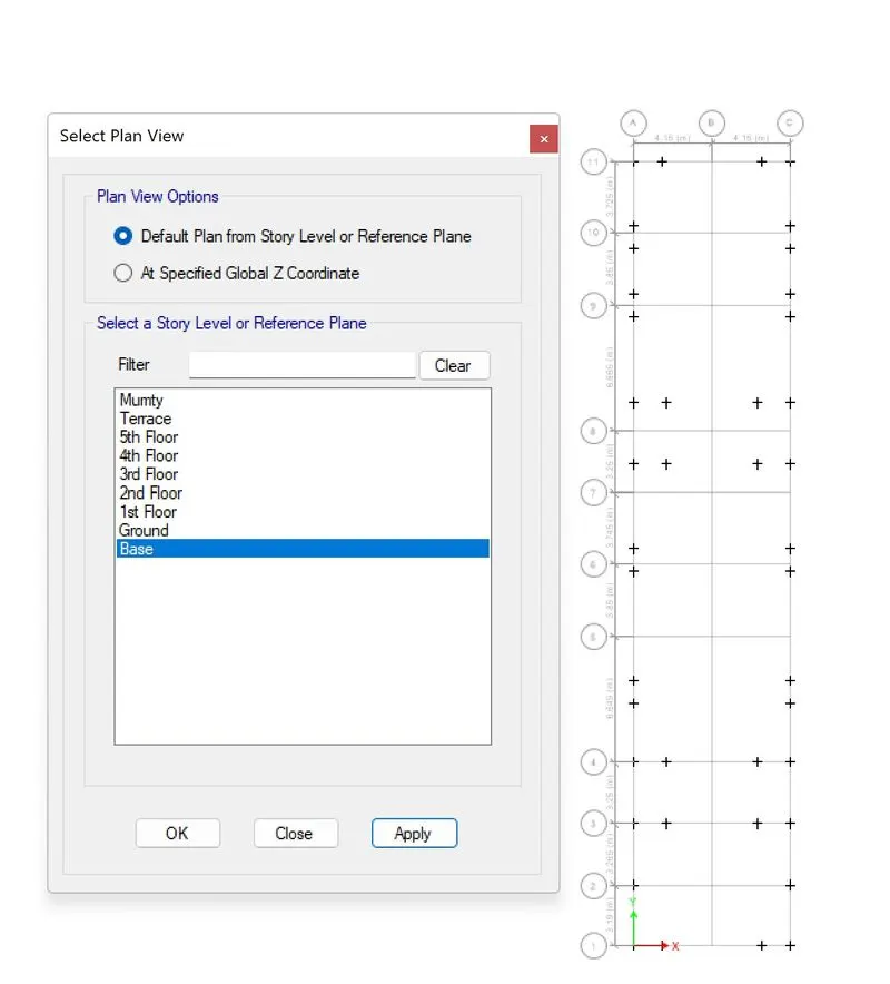
3. Elevation > Base
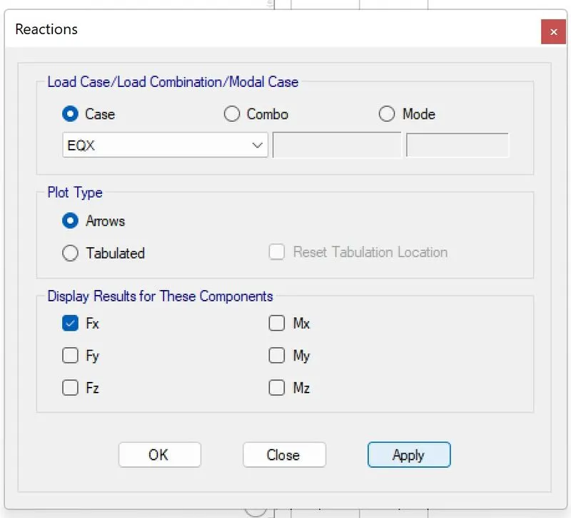
4. Display Support/Spring Reactions> case> EQX ( Earthquake in X direction ) :
5. It will show the shear force values as following :
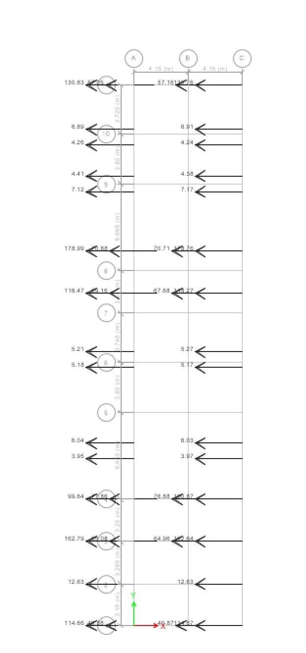
- The summation of the values divided by the Total Base Shear will give the % shear forces taken up by the shear walls.
- This percentage should be more than 80%, if not we need to add more shear.
- Also, 25% shear is taken up by the Moment Resisting Frames.
6. Total Base Shear is calculated by : Display > Show tables > Structure output > Base Reactions:
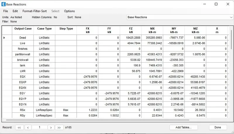
Here, at EQX the total base shear is given as -2479.9576.
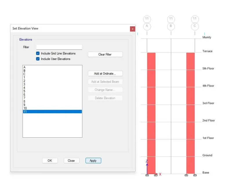
7. Select Elevation > 11 ( grid A11 ) ;
8. Shear wall design > View shear wall references > OK :
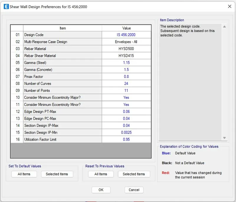
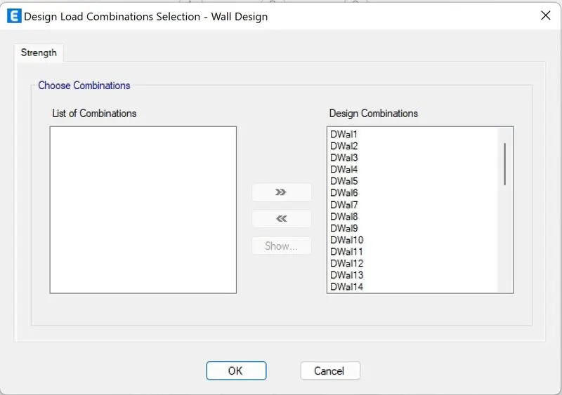
9. Shear wall design > Load combinations :
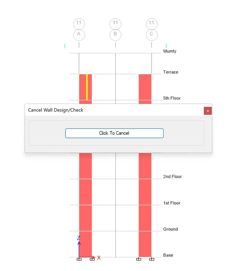
10. Shear wall design > Design start/check :
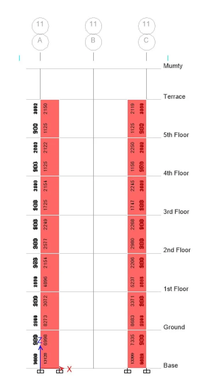
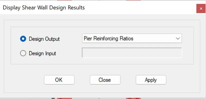
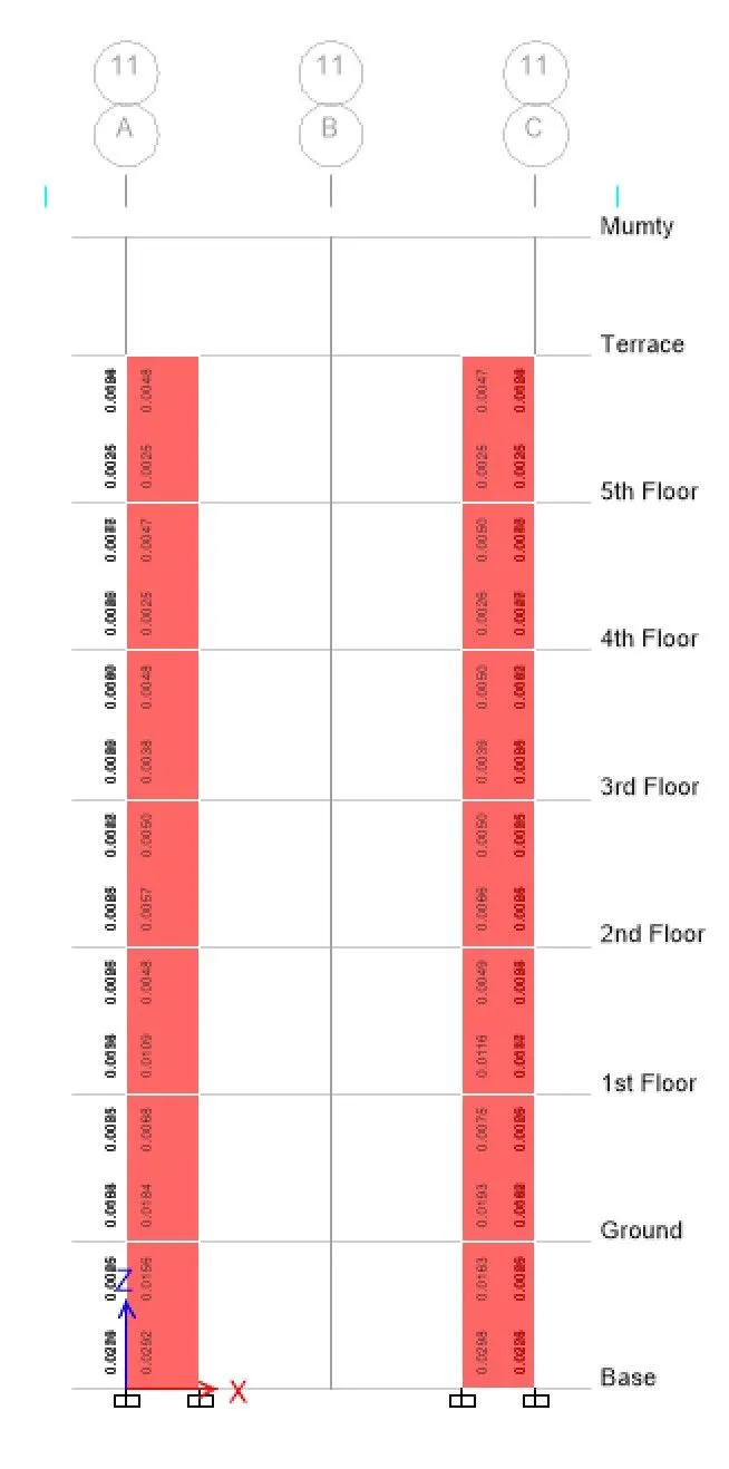
11. Shear Wall Design > Display Design Info : Pier Reinforcing ratios : Extract the values from output results :
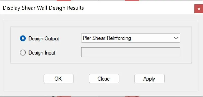
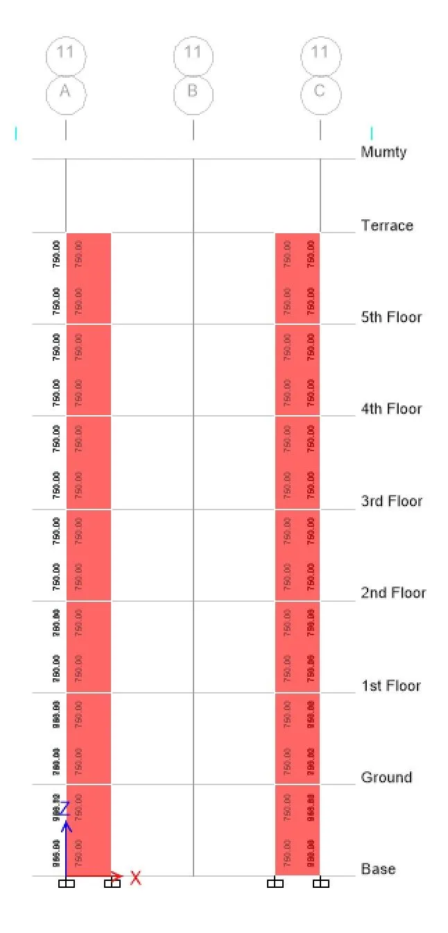
12. Shear Wall Design >Display Design Info > pier Shear reinforcing :
13. Shear Wall Design >Display Design Info > Pier Edge/Boundary Zones :
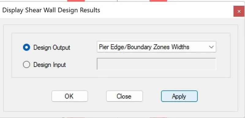
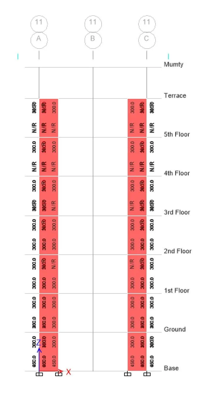
14. Right Click on any shear wall and the following details will be displayed -
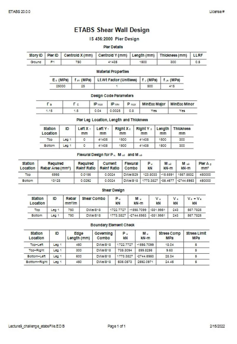
CALCULATION OF SHEAR WALL DETAILS WITH ACCORDANCE TO IS 13920 2016 -
a.
- Overall height of wall h = 21000mm
- Length of wall L = 1500mm
- Ratio of h/L = 14 > 2
- Hence the wall is of type = Slender.
b.
- Largest Diameter that can be used in shear walls should not exceed 1/10th of thickness of wall = 300mm thickness
- 300/10= 30mm
- 12mm bar is used for detailing so OK.
c. the maximum spacing of shear should not exceed [CLAUSE 10.1.9]
- 1/5th horizontal length of wall = 1500/5 = 300mm
- 3 times thickness of wall = 30 X 3 = 900mm
- 450mm
Hence adopt 300mm spacing for both vertical and horizontal reinforcement.
d. Minimum horizontal reinforcement in RC shear wall - [ CLAUSE 10.1.6 Table 1 ]
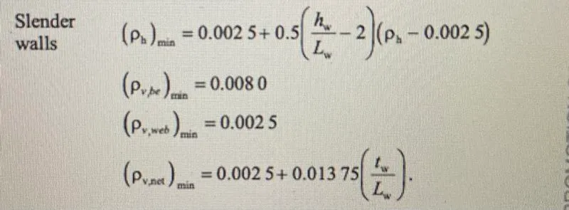
- (use 1st one )
- 0.0025 + 0.5 (21000/1500)(0.029X1500X300)
- = 0.01672 X cross section of wall
- = 0.01672 X 1500 X 300 = 7524 mm^2
- 7524/21 = 358 mm^2/m height of wall
Hence , provide 16mm dia at 100mm c/c spacing.
thus , 1000/100 X 2 X 201 = 4020 mm^2 .OK
e. Minimum boundary reinforcement calculation as per [CLAUSE 10.1.6 Table 1]
- (use 2nd )
- 0.008 X 300 X 300 = 720mm^2/m
Provided minimum 8 bars of 12mm dia. 8X113 = 904mm^2 . OK
f. Minimum web reinforcement [CLAUSE 10.1.6 Table 1]
- (use 3rd)
- 0.0025 (1500-300-300) X300
- 0.0025 X 900 X300
- 675mm^2/m
g. Minimum RC wall vertical reinforcement [CLAUSE 10.1.6. Table 1]
- (use 4th)
- 0.0025 + 0.01375 (300/1500)
- = 0.00525 X cross section of wall
- 0.00525 X 1500 X 300 = 2362 mm^2/m
Provided min 24 bars of 12mm dia = 24 X 113= 2712 mm^2/m, OK
h. Boundary element special confining reinforcement [CLAUSE 10.4.4]
- Max spacing of confinement is 100mm
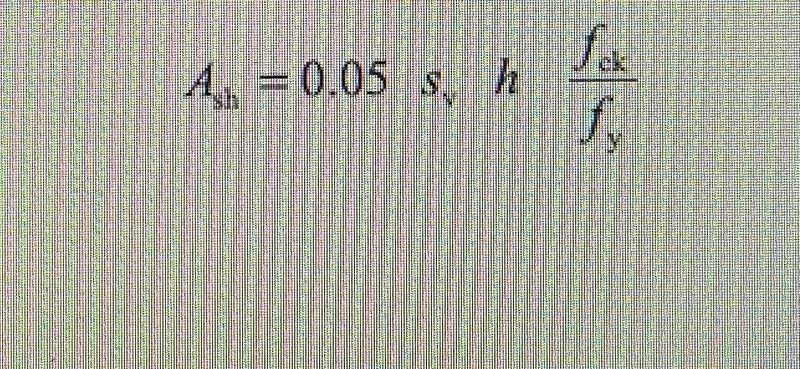
- = 45mm^2/m
- h = min clear distance between longitudinal rebar = 150mm
Provide 2 closed links of 16mm dia
2 X 201 = 402 mm^2/m , OK
CONCLUSION -
The Design of RC SHEAR WALL is done in accordance with IS 13920:2016.