Analysis & Design of RCC shear walls in the model using ETABS
Aim: Detailing of shear wall
Procedure:
Step 1: The provided ETABS model is analysed and the shear wall design is run as shown in the figure below.
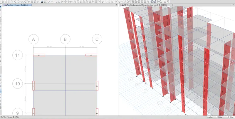
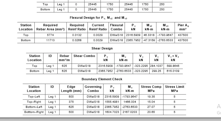
Step 2: The mentioned shear wall is labelled as P1. The design results of pier P1 is extracted as shown below.
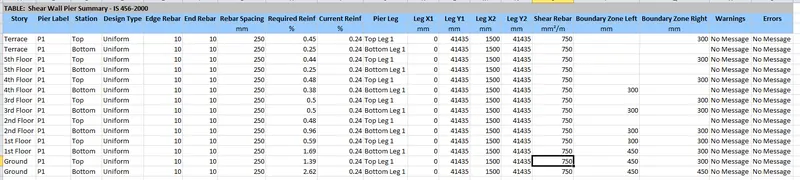
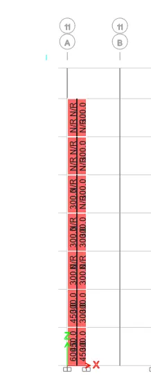
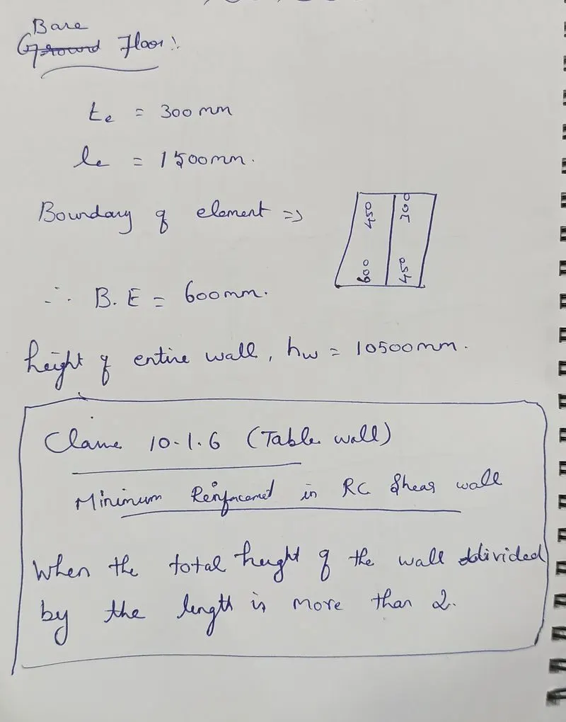
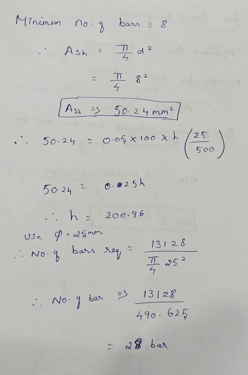
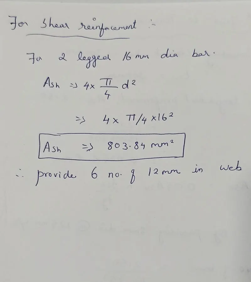
From the obtained results, it can be seen that a boundary zone of 450mm is required each side. When the boundary element length is removed only 600mm of the web portion is left. Thus the entire wall is provided with confinement reinforcement.
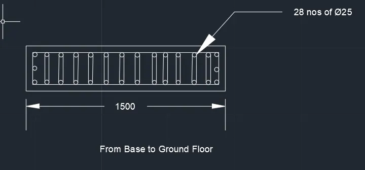
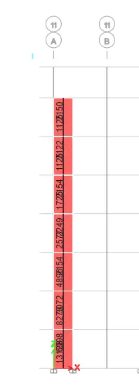
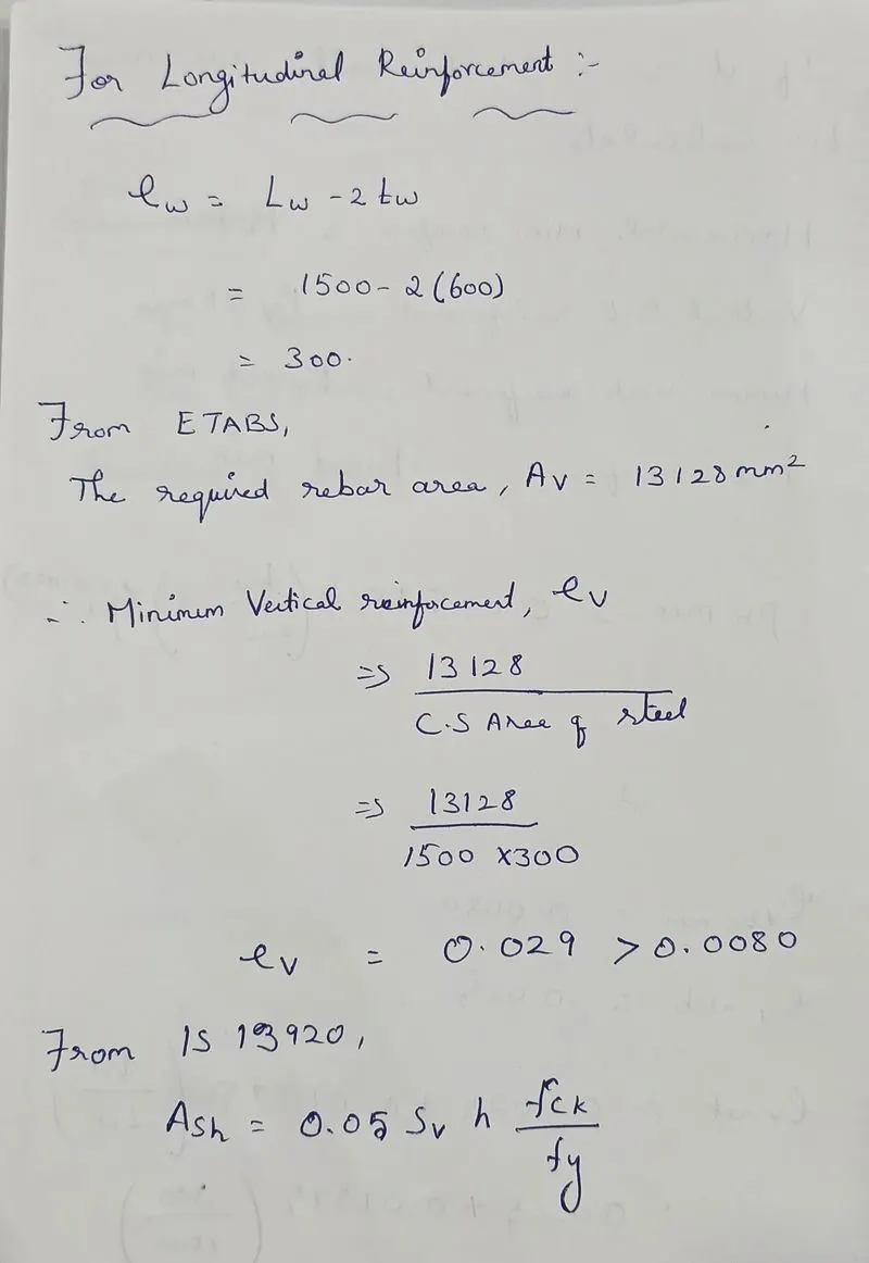
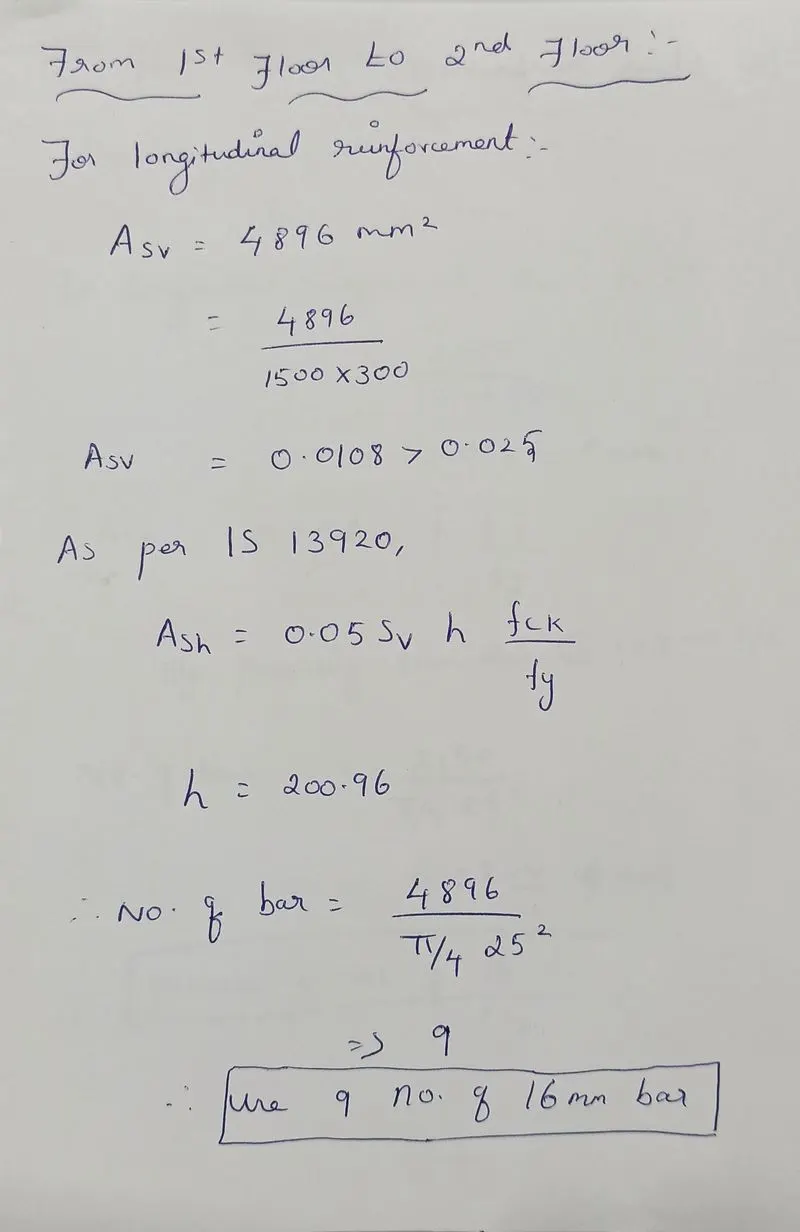
The maximum reinforcement at ground floor is 2.62. Thus Area of longitudinal steel will come upto 11790 sq-mm.
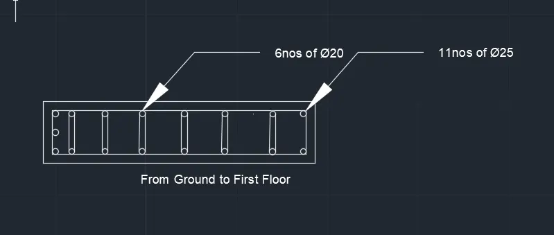
Considering 150mm spacing between longitudinal reinforcement, 11 bars can be provided on each face and one bar each extra at the shorter direction of the wall as shown below. The the reinforcement of the wall at ground floor comes is as shown below.
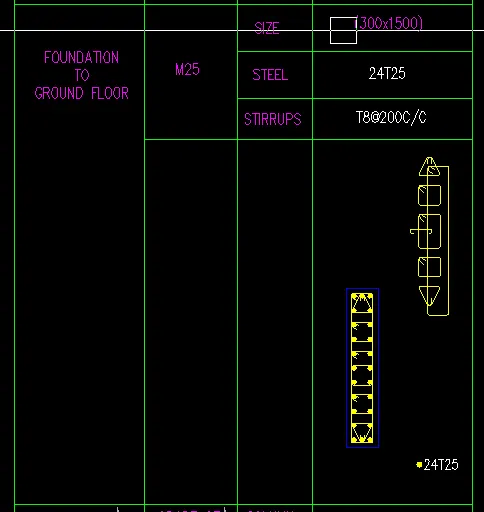
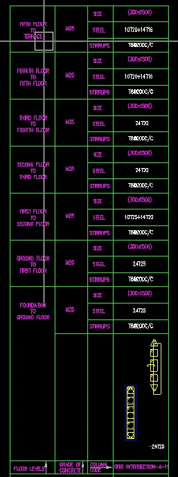
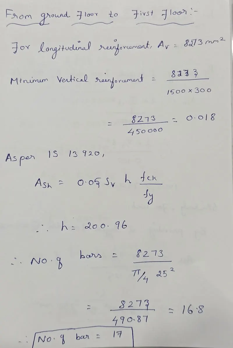
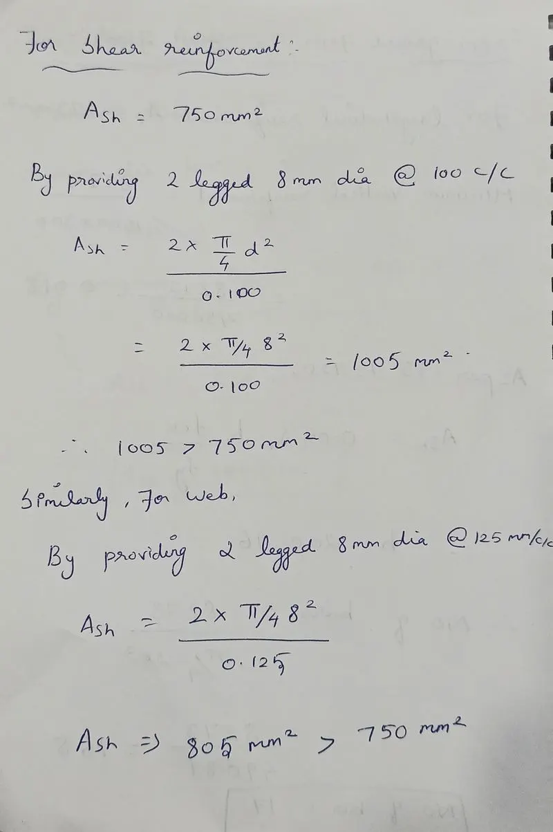
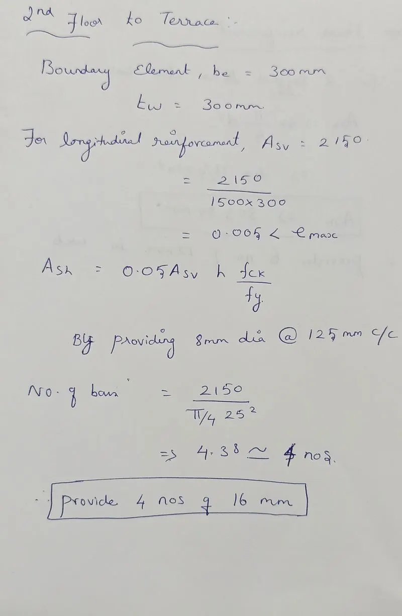
Thus the reinforcement for the above floors is as shown below.
Aim:
To run the analysis and design the RCC shear walls shown in the etabs model.
Step 1:
1) Open the ETABS file
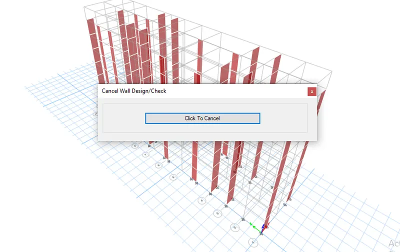
2) After the analysis click Concrete frame design
Step 2:
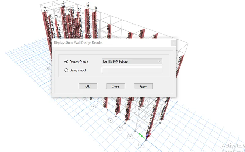
1) Need to check there is any failures occurs
2) Click Shear wall design tool
3) select Display info and choose PM failure
Step 3:
1) Click any wall and check the details
2) Here there is no failure occurs all the values of reinforcement ratio is within 4%
Step 4:
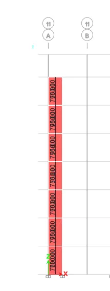
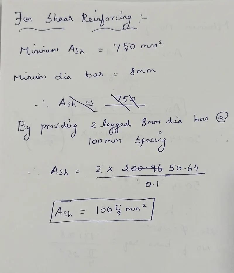
Shear Reinforcing
1) Go to concrete frame design
2) Click Display design info
3) Choose Shear reinforcing
Step 5:
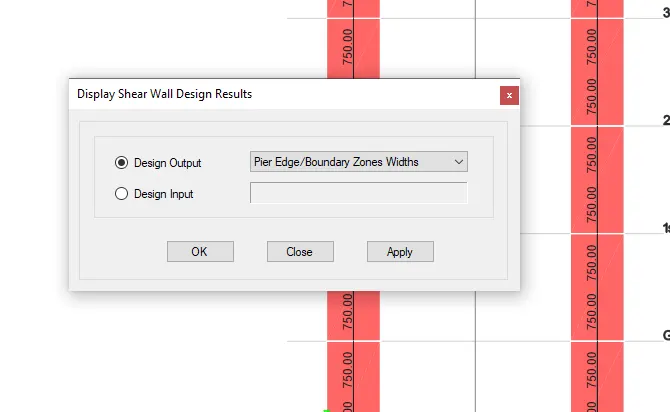
Boundary element width
1) Go to concrete frame design
2) Click Display design info
3) Choose Pier edge or boundary zone width
Step 6:
Longitudinal Reinforcement:
1) Go to concrete frame design
2) Click Display design info
3) Choose Pier longitudinal reinforcing
Calculations:
Drawings: