Analysis & Design of RCC shear walls in the model using ETABS
The etabs file for a G+6 building is provided. Run the analysis and design the RCC shear walls (show in the etabs model). The following challenge deals specifically with the shear wall of size 300x1500 at grid A-11 in the structural model.
- Extract values of longitudinal steel ratio, boundary element length and shear reinforcing ratio from the design results.
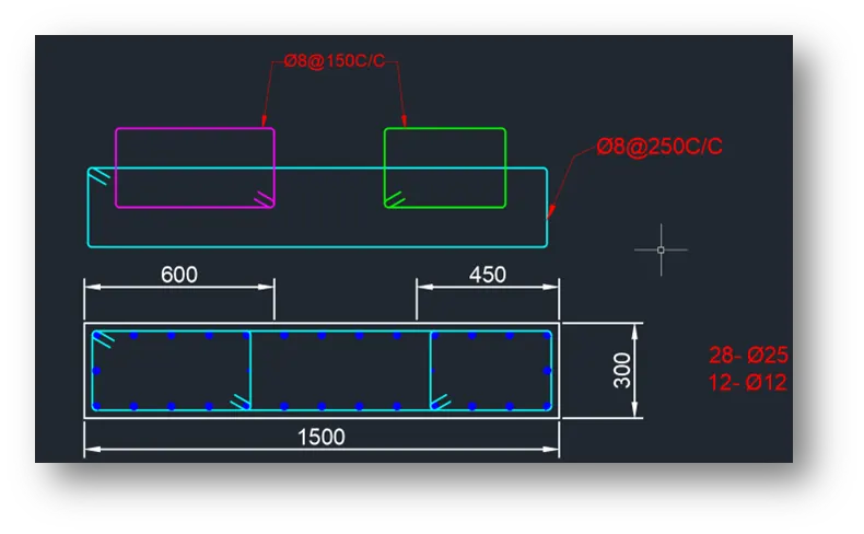
- Provide cross sectional steel arrangement of the shear wall from its base up to terrace, in compliance with provisions of IS 13920 – 2016. AutoCAD application can be used for this exercise. Alternatively, it can be drawn by hand as well.
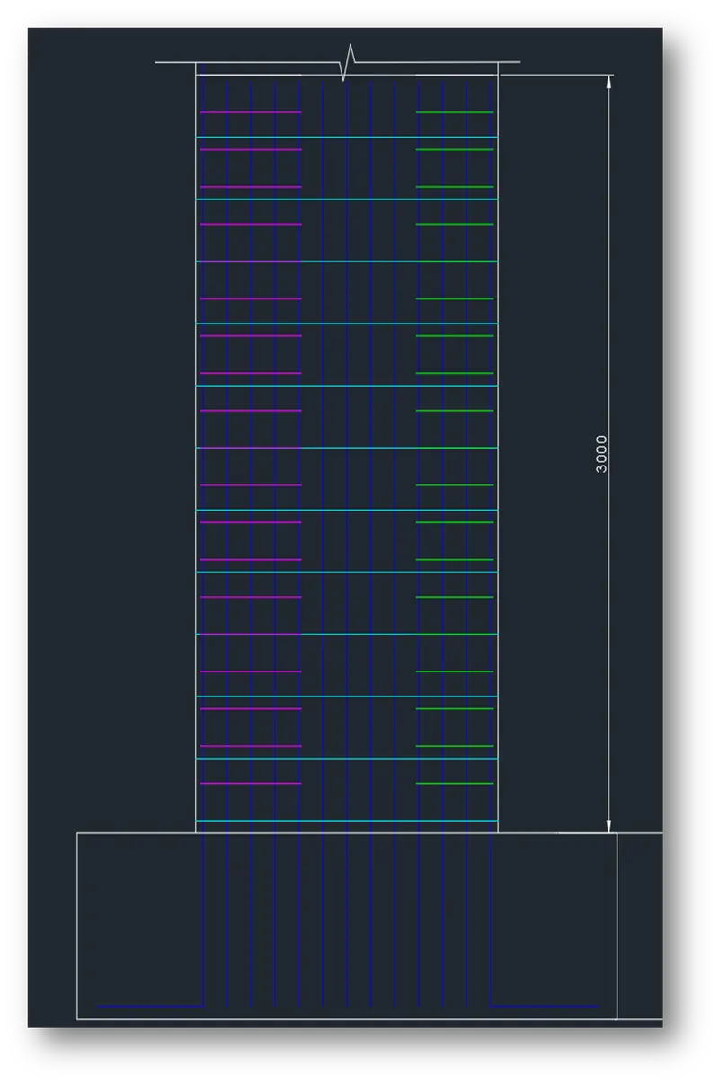
- Provide elevation drawings of the reinforcement details of the shear wall from base up to terrace.
AIM:
To know the design of RC shear wall using ETABS analysis, to know the basics of shear wall reinforcement detailing with respect to primary standards and to ensure the ductility reinforcement required by IS-13920-2016 been satisfied in reinforcement drawing
INTRODUCTION:
In the modal we provide the details of RCC shear wall of size 300X1500mm at grid A-11 and result taken from the provided ETABS model of G+6 building.
PROCEDURE:
STEP 1) Open the Given Model
- Model open in etabs software
- Check the model
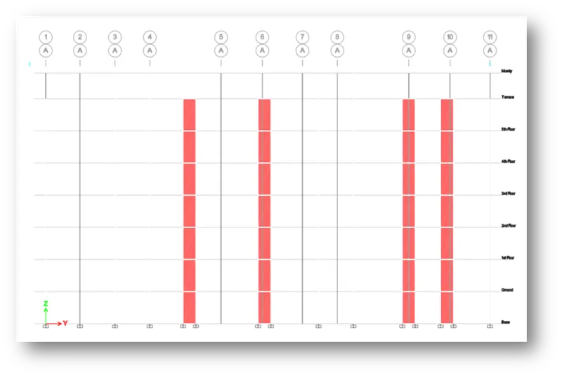
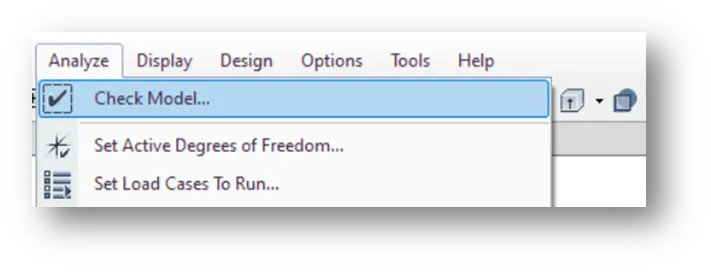

STEP 2) Analysis of Shear wall
- Select the shear wall at intersection A-11 from terrace to foundation
- To ensure the pier assignment done for all column
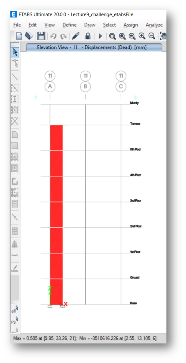
- Click on run analysis it will show the max. & min. deflection at the bottom
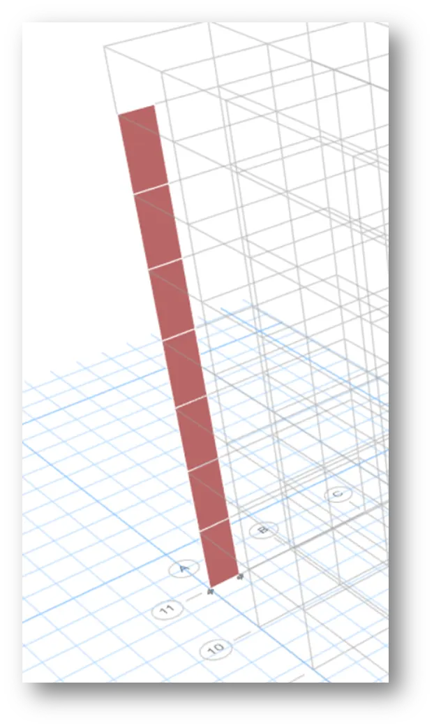
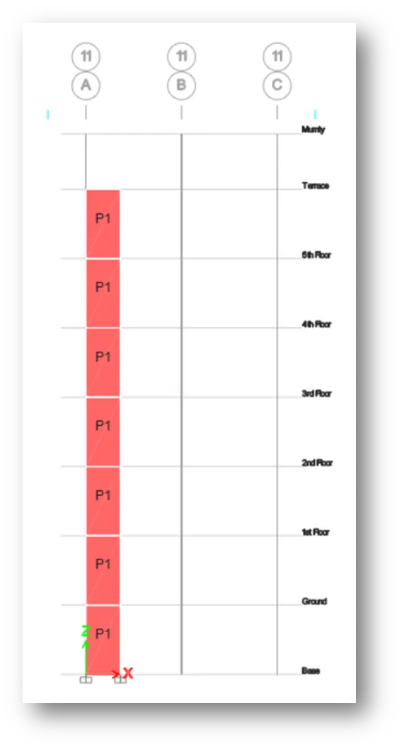
STEP 3) Reinforcement Detail Shear Wall
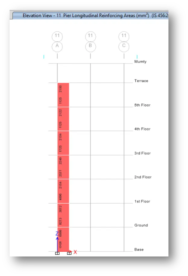
- Click on shear wall design icon
- It will show the longitudinal or vertical reinforcement of the shear wall
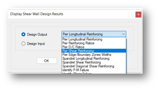
- Drop down the icon shear wall design and click on display design info
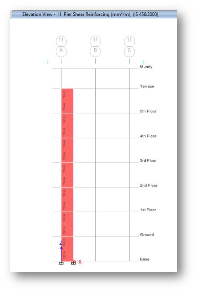
- Select shear reinforcement in display shear wall design result
- It will show the shear or horizontal reinforcement of the shear wall
- Again, drop down the icon shear wall design and click on display design info
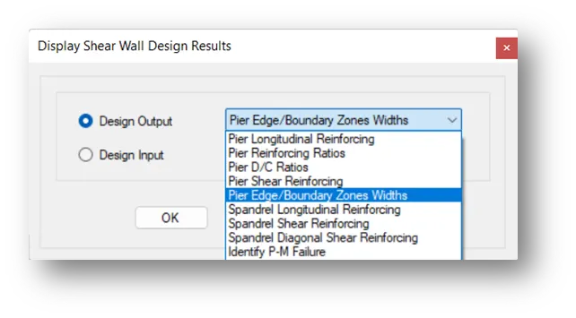
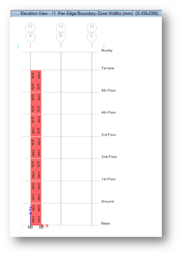
- Select per edge boundary zones width
- It will show the boundary edges
STEP 4) Shear Wall Reinforcement Design
The detailing guideline for shear wall
- Minimum reinforcement for shrinkage & temperature
- Ultimate limit state design rebar requirement
- Ductility rebar requirement
Whichever is greater, should be drawn in RC shear wall detailing
- Classification of shear wall as pr is 13920-2016 clause 10.1.4
slender wall hw/lw=21000/1500=14>2
- Minimum net vertical reinforcement as per IS 13920-2016 table-1 (iii)
2363`mm^2`=0.0025+0.01375(300/1500)
- Minimum vertical reinforcement within boundary element table-1 (iii)
1440`mm^2` on left (600mm width boundary element)
1080`mm^2`on right (450mm width boundary element)
- Minimum horizontal reinforcement in shear wall as per IS 13920-2016 table-1 (iii)

`rho`h = 750/(300X1000) = 0.0025, hw = 21000, lw = 1500
`rho`hmin = 0.0025 + 0.5 (21/15-2) x 0
`rho`hmin = 0.0025 which is the same 750 `mm^2`/m
- Maximum diameter of rebar for shear wall as per IS 13920-2016 clause 10.1.8
1/10th of wall thickness = 300/10 =30mm
Commercial rebar diameter 25mm shall be adopted
- Confining reinforcement spacing for boundary element as per IS13920-2016 clause 10.4.4
- 1/3 of minimum member dimension = 300/3 = 100mm
- 6 times smallest main rebar = 6x25 =150mm
- 150mm permissible if vertical bars are spaced at maximum 200mm
- Maximum spacing of confining reinforcement in boundary element 150mm
- Confining reinforcement within boundary element as per IS-13920-2016 clause 10.4.4
Ash = 0.05 sv h fck/fy
Sv = 150mm, h = 1000mm
Ash = 452 mm2
RESULT:
Successfully done the designing and detailing of provided the details of shear wall reinforcement at grid A-11 from foundation to terrace level as per IS 13920:2016 and sketch the cross section/ elevation in AutoCAD software