Analysis & Design of RCC shear walls in the model using ETABS
Aim:
To know the design of RC shear wall using ETABS analysis, to know the basics of shear wall reinforcement detailing with respect to primary standards and to ensure the ductility reinforcement required by IS-13920-2016 been satisfied in reinforcement drawing.
Objective:
- Analysis of the Shear Wall using ETABS.
- Detailing of the reinforcement shear wall.
- To design the Shear wall reinforcement
Procedure:
1. Analysis of the Shear Wall using ETABS.
Step 1: Open the given Model.
- Download the model by clicking on click here for the Attachment in the Dashboard.
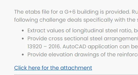
- Now double click on the model to open the Project in the ETABS.
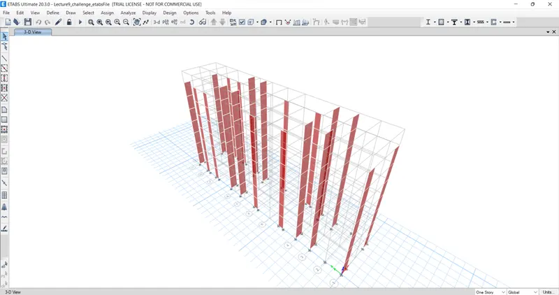
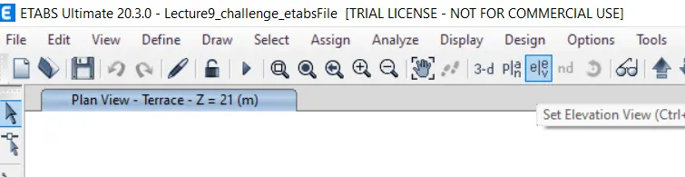
Step 2: Now go to the Terrace view Select the shear wall at intersection A-11.
- Click on the plan view in the Title box
- then click on the terrace to Open the terrace view.
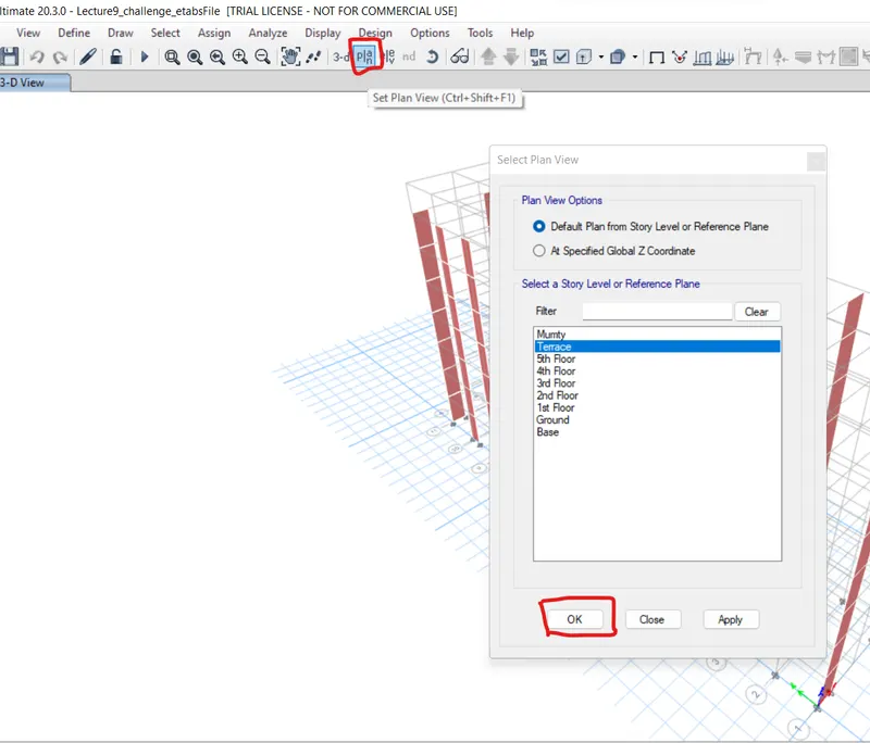
- Now Change the story option to call stories.

-
Select the shear wall at intersection A-11.
-
And by right click click on the show selected objects only.
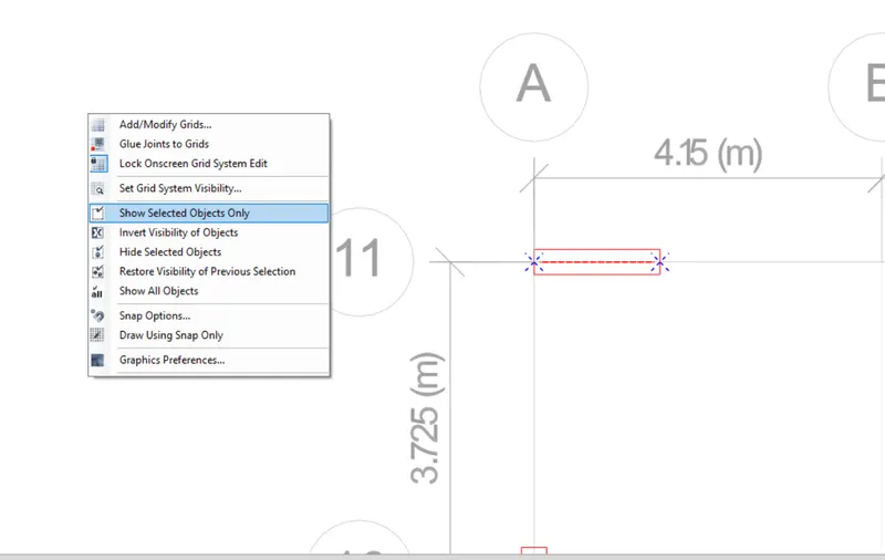
- Now click on the elevation view and select the 11 in it.
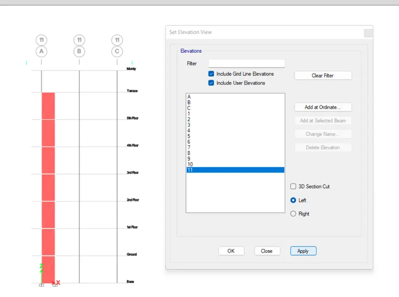
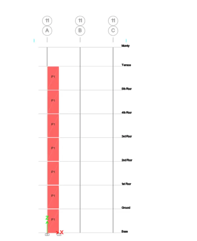
Step 3: To ensure the pier assignment is done for the shear walls or not.
-
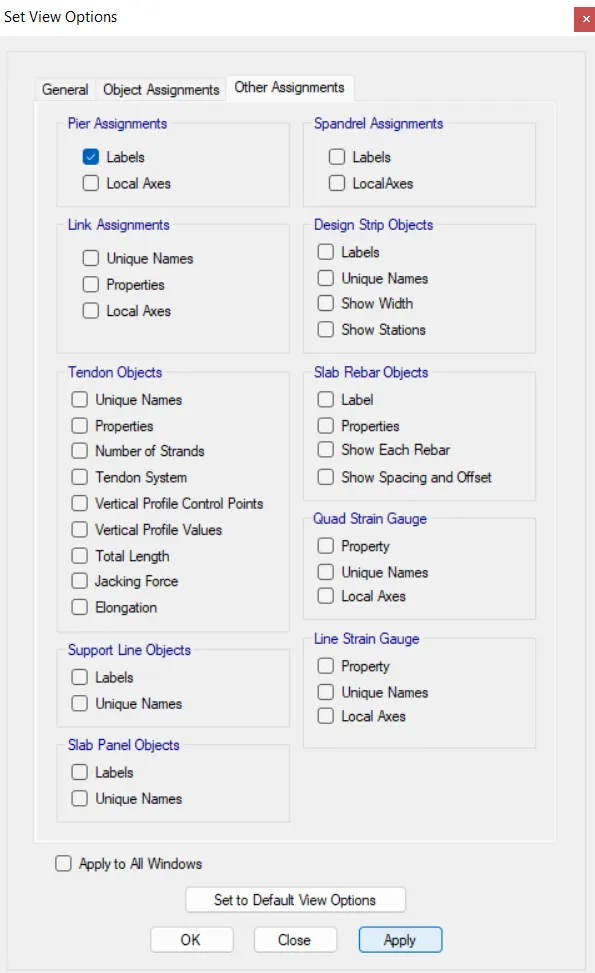
Click on set display option.

- Then click on. other assignments and check the labels option, click on Ok.
Step 4: Run the analysis
- Click on the run analysis button to start, then analysis.

2. Detailing of the reinforcement shear wall.
Step 1: To show the longitudinal or vertical reinforcement of the shear wall
- Now. Click on the shear wall icon that is visible on the right side.

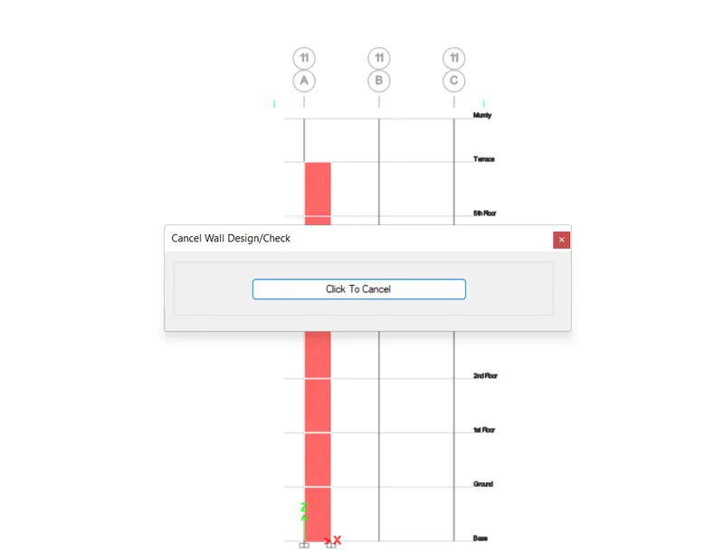
-
You will see the longitudinal Reinforcement steel is visible.
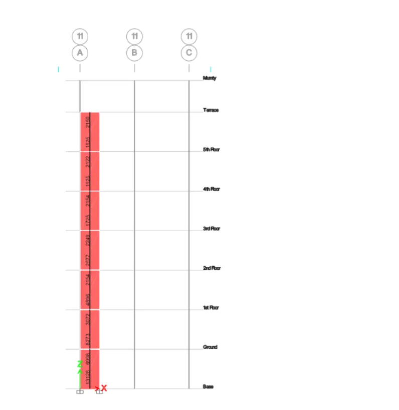
-
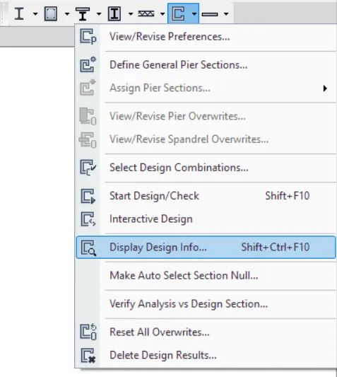
Drop down the icon shear wall design and click on display design info
- Select shear reinforcement in display shear wall design result
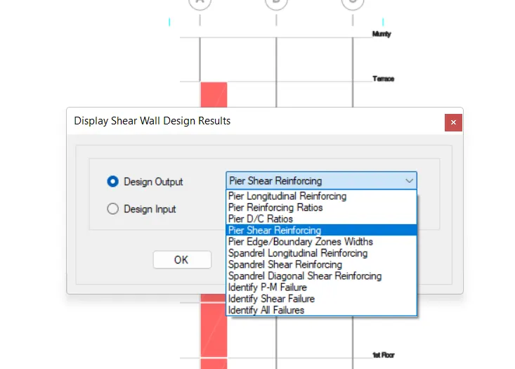
- You will see here the horizontal shear reinforcement design.
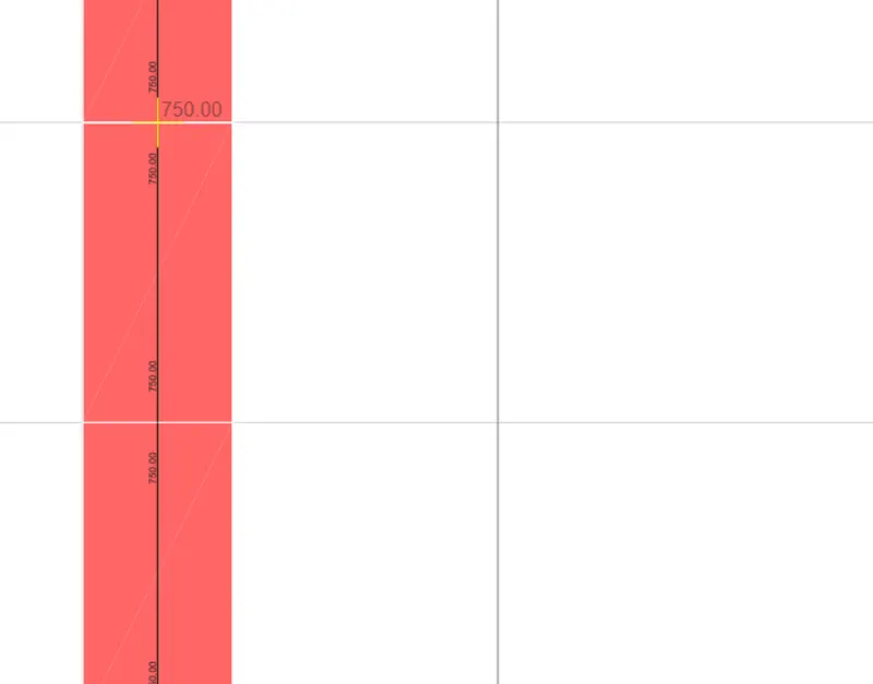
- Again, drop down the icon shear wall design and click on display design info
- Select per edge boundary zones width
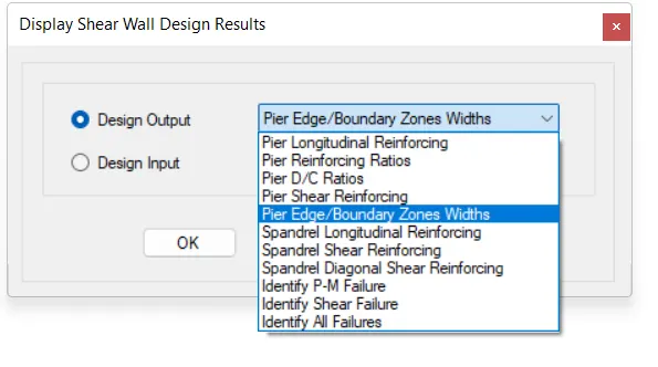
- It will show the boundary edges
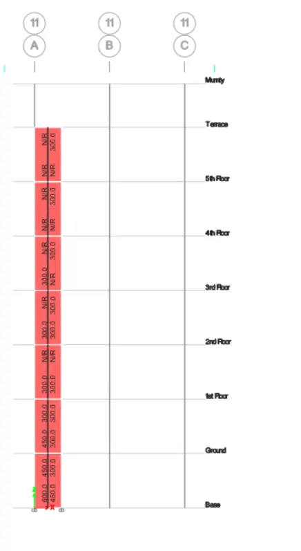
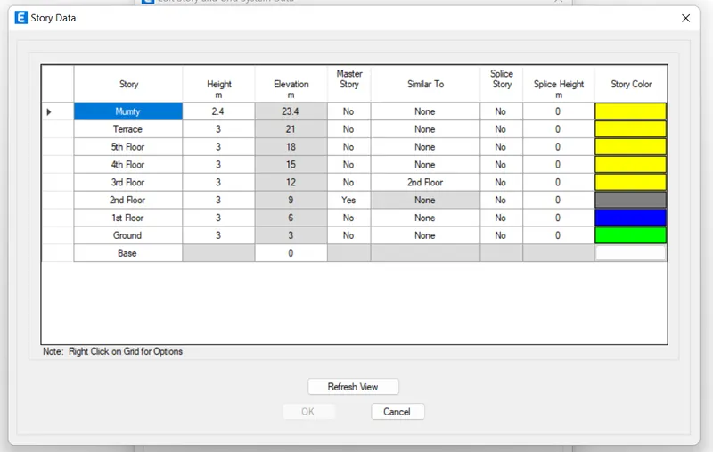
For this model also we will note the story elevation so, for drawing the elevation of shear wall we will need storey data.
3. To design the Shear wall reinforcement:
Deatiling Guideline for shear wall:
Whichever is greater should be drawn in RC shear wall detailing.
- Minimum reinforcement for shrinkage & temperature
- Ultimate limit state design rebar requirement
- Ductility rebar requirement
Classification of shear wall as pr is 13920-2016 clause 10.1.4
- slender wall hw/lw=21000/1500=14>2
Minimum net vertical reinforcement as per IS 13920-2016 table-1 (iii)
- 2363mm2 =0.0025+0.01375(300/1500)
Minimum vertical reinforcement within boundary element table-1 (iii)
- 1440mm2 on left (600mm width boundary element)
- 1080mm2 on right (450mm width boundary element)
Minimum horizontal reinforcement in shear wall as per IS 13920-2016 table-1 (iii)

(rho)h = 750/(300X1000) = 0.0025, hw = 21000, lw = 1500
(rho)h min = 0.0025 + 0.5 (21/15-2) x 0
(rho)h min = 0.0025 which is the same 750 mm2 /m
Maximum diameter of rebar for shear wall as per IS 13920-2016 clause 10.1.8
1/10th of wall thickness = 300/10 =30mm.
Commercial rebar diameter 25mm shall be adopted.
Confining reinforcement spacing for boundary element as per IS13920-2016 clause 10.4.4
- 1/3 of minimum member dimension = 300/3 = 100mm
- 6 times smallest main rebar = 6x25 =150mm
- 150mm permissible if vertical bars are spaced at maximum 200mm
- Maximum spacing of confining reinforcement in boundary element 150mm
Confining reinforcement within boundary element as per IS-13920-2016 clause 10.4.4
Ash = 0.05 sv h fck/fy
Sv = 150mm, h = 1000mm
Ash = 452 mm2
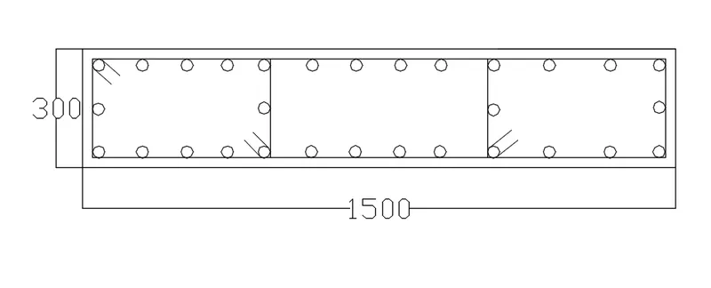
28 numbers 25mm DIA
2 numbers 12 mm Dia
Baundary element bar
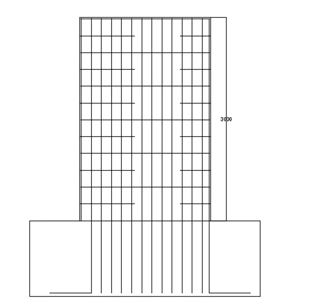
Overall Stirrup 1 link B.E Stirrup 2 links
8mm DIA 250mm spacing 8mm DIA 150mm spacing