Analysis & Design of RCC shear walls in the model using ETABS
- ANALYSIS AND DESIGN OF RCC SHEAR WALLS IN THE MODEL USING ETABS :
- QUESTION
- The etabs file for a G+6 building is provided. Run the analysis and design the RCC shear walls (show in the etabs model). The following challenge deals specifically with the shear wall of size 300x1500 at grid A-11 in the structural model.
- Extract values of longitudinal steel ratio, boundary element length and shear reinforcing ratio from the design results.
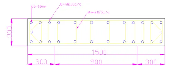
- Provide cross sectional steel arrangement of the shear wall from its base up to terrace, in compliance with provisions of IS 13920 – 2016. AutoCAD application can be used for this exercise. Alternatively, it can be drawn by hand as well.
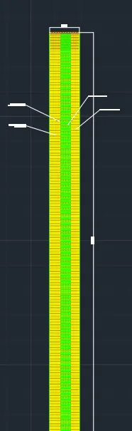
- Provide elevation drawings of the reinforcement details of the shear wall from base up to terrace.
- AIM :
- Design Of Shear Wall Using Etabs 2017
- PROCEDURE :
- STEP : 1
- Download the file given in the attachment
- then start the ETABS 2017 software
- then go to the file manu
- and click on IMPORT option
- and select the file and click ok
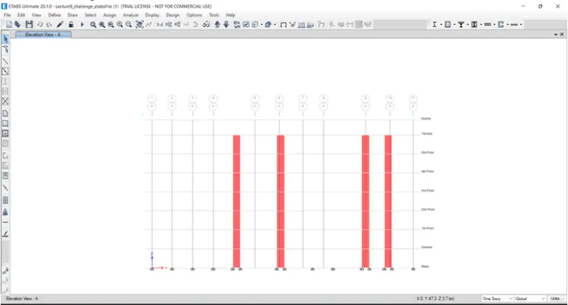
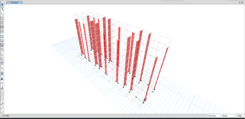
- STEP 2
- Run Analysis
- after analysis is completed
- STEP 3
- Click on concrete frame design to check the shear wall
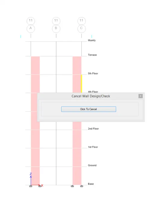
- Since, we have gathered the necessary information, now we need to draft the details of a RC wall in AutoCAD for the wall at All.
- Shear wall detailing calculations:
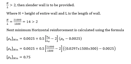
- Here, the total height of the wall is 21000mm and the width of the wall is 1500mm.
- Hence, the ratio is obtained as 21000 /1500 = 14which is greater than 2
- hence, it can be considered as a slender wall.
- Maximum diameter of the bar that can be used from IS code = 1/10th of thickness of that part = 30mm
- Hence, we take the dia of bar as 25mm.
- Maximum spacing between the bars should not exceed the minimum of the following:
- 1/5 x 1500 300mm
- 3x300 900mm
- 450 mm
- Hence, the maximum spacing is limited to 300mm.
- Longitudinal reinforcement:
- Go to Design Info
- Select Longitudinal Reinforcement
- Click ok
- Results have been attached below
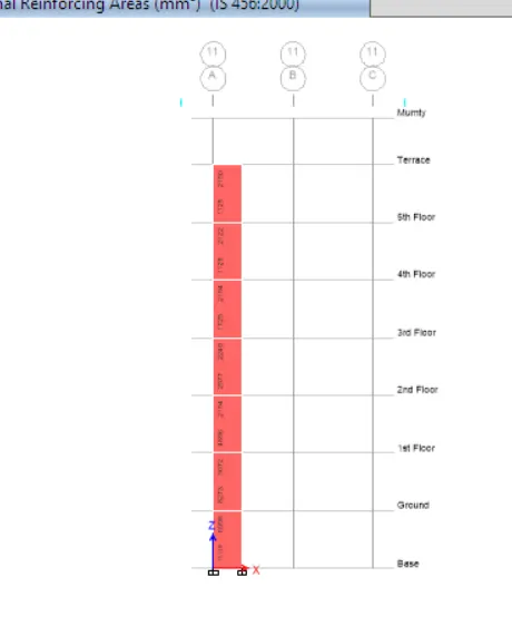
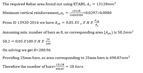
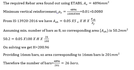
- From ETABS results the maximum is longitudinal reinforcement obtained 13128mm².
- Since we are using 25mm dia bars, the no. of bars required will be 13128 /490 =28bars. But we are providing two additional bars in the boundary element for proper confinement.
- i.e total 30 longitudinal bars.
- Hence the total area of reinforcement provided is 13720mm². Hence, it is safe.
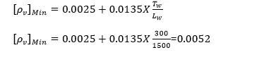
- Now, from the code the minimum vertical reinforcement required is 0.0025+0.01375 (tw/Lw)
- = 0.00525, l.e0.00525x300x1500 = 2362.5mm2 which is less than actually provided hence safe.
- Now, minimum vertical reinforcement to be provided in the boundary region = 0.008 x 1500 x 300 = 3600mm².
- The reinforcement provided for boundary element in right side = 4410 mm²and
- At left side = 5390mm Both are greater than the required value i.e 3600mm². Hence safe.
- In the web area the minimum reinforcement provided is 0.0025x1500x300-1125mm² and the provided amount of reinforcement in web area is 3920mm².Hence it is safe.
- Horizontal reinforcement:
- Go to design check
- and select Peir Shear Reinforceing
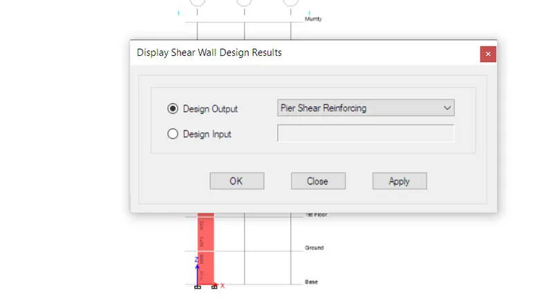
- Click on apply and then ok.
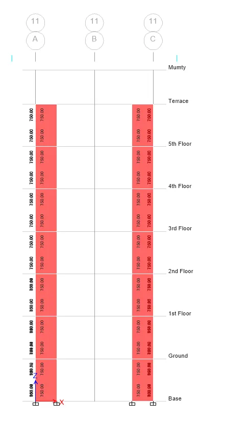
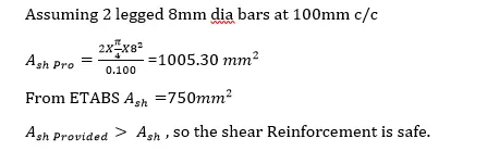
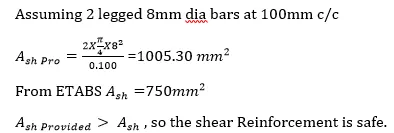
- From Etabs results the shear reinforcement amount is obtained as 750mm2.
- So let us provide 8mm dia bars @ 100 mm c/c, then the provided area of reinforcement will be 1000mm².
- STEP
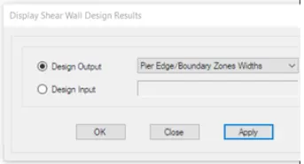
- Now check the boundary element
- Go to design check
- and select Boundary zones widths
- Click ok
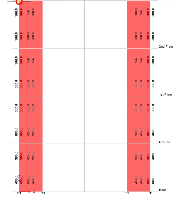
- From clause 10.4.4, the shear reinforcement required in the boundary element can be obtained from the equation
-
Step 5) - Shear wall detailing calculation .
1) Base Floor to 1st Floor -
Therefore , Minimum vertical reinforcement
a)
i) Longitudinal Reinforcement Calculations -
b) Shear Calculation -
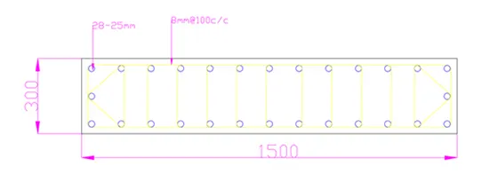
2) First Floor to Second Floor -
i) Longitudinal Reinforcement Calculations -
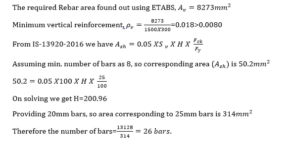
b) Shear Calculation -
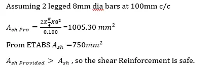
Note - Boundary element length is reduced as we move up . It means that Stresses are reduces .
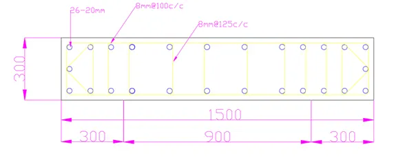
3) Second Floor to Third Floor -
i) Longitudinal Reinforcement Calculations -
b) Shear Calculation -
-
Result -
i) Shear wall is designed successfully .
ii) All the checks are done as per IS 13920 - 2016 .