Air Standard Cycle
AIM:
To write code that can solve an Otto Cycle and make plots for it and also calculate the thermal efficiency of the engine.
INTRODUCTION:
The Otto cycle is a set of processes used by spark ignition internal combustion engines (two-stroke or four-stroke cycles). Nikolaus August Otto first designed what is known as the four-stroke engine. A stroke refers to the full travel of the piston along the cylinder, in either direction. It is the one of most common thermodynamic cycles that can be found in automobile engines and describes the functioning of a typical spark ignition piston engine.
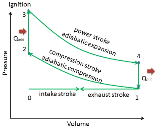
Otto Cycle P-V Diagram:
Working of Spark Ignition Engine:
The fuel from the carburetor is used to enter the combustion chamber at the time of suction stroke by moving the piston downwards by opening the inlet valve and this fuel gets compressed by moving the piston upwards when the piston moves maximum to the top of the cylinder the spark plug produces a spark to ignite the fuel and generates huge power and this power is used to store in the flywheel and reused when it is required and at the time of compression and ignition both the inlet and outlet valves gets closed, after the ignition process the burned fuel develops hot waste gases and this waste gas passes out at the time of exhaust stroke by opening the outlet valve.
Otto Cycle-Processes:
1. Isentropic compression (compression stroke) – The gas (fuel-air mixture) is compressed adiabatically from state 1 to state 2, as the piston moves from bottom dead center to top dead center. This increases its internal energy (temperature) and compresses it. On the other hand, the entropy remains unchanged. The changes in volumes and the ratio (V1 / V2) is known as the compression ratio.
`P*V^gamma = constant`
`(P_1V_1)/T_1 = (P_2V_2)/T_2`
2. Constant volume heat addition (ignition phase) – In this phase (between state 2 and state 3) there is a constant-volume (the piston is at rest ) heat transfer to the air from an external source while the piston is at rest at the top dead center. This process is intended to represent the ignition of the fuel-air mixture injected into the chamber and the subsequent rapid burning.
`V_2 = V_3`
Using the ideal gas equation:
`(P_3V_3)/T_3 = (P_2V_2)/T_2`
3. Isentropic expansion (power stroke) – The gas expands adiabatically from state 3 to state 4, as the piston moves from top dead center to bottom dead center due to the increase in the temperature and pressure inside the combustion chamber. Again the entropy remains unchanged. The volume ratio (V4 / V3) is known as the isentropic expansion ratio, but for Otto cycle, it is equal to the compression ratio.
`P_3V_3^gamma = P_4V_4^gamma`
4. Constant volume heat rejection (exhaust stroke) – In this phase the cycle completes by a constant-volume process in which heat is rejected from the air while the piston is at the bottom dead center. The working gas pressure drops instantaneously from point 4 to point 1. The exhaust valve opens at point 4. The exhaust stroke is directly after this decompression. As the piston moves from the bottom dead center (point 1) to the top dead center with the exhaust valve opened, the gaseous mixture is vented to the atmosphere and the process goes on.
`V_4 = V_1`
Formula's used:
Volume change inside the combustion chamber is calculated by
`V/V_c =1+1/2(cr-1)[R+1-costheta-(R^2-sin^2theta)^0.5]`
Thermal efficiency of the Otto Cycle is calculated by
`eta = 1-(1/(cr^gamma-1))`
Programming part:
clear all
close all
clc

%Inputs
gamma = 1.4
t3 = 2300

%State variables
p1 = 101325
t1 = 500

%Engine geometric parameters
bore = 0.1;
stroke = 0.1;
con_rod = 0.15;
cr = 12;

%Calculating the swept volume and the clearance volume
v_swept = (pi/4)*bore^2*stroke;
v_clearance = v_swept/(cr-1);

v1 = v_swept + v_clearance
v2 = v_clearance

%State variables at state point 2
%p2v2^gamma = p1v1^gamma
%p2 = p1*(v1/v2)^gamma = p1*cr^gamma
p2 = p1*cr^gamma

%p1v1/t1 = p2v2/t2 | t2 = p2*v2*t1/(p1*v1)
t2 = p2*v2*t1/(p1*v1);

%State variables at state point 3
v3 = v2

%p3v3/t3 = p2v2/t2 | p3 = p2*t3/t2
p3 = p2*t3/t2

%State variables at state point 4
v4 = v1

%p3v3^gamma = p4v4^gamma | p4 = p3(v3/v4)^gamma
p4 = p3*(v3/v4)^gamma

figure(1)
hold on
plot(v1,p1,'*','color','r')
plot(v2,p2,'*','color','r')
plot(v3,p3,'*','color','r')
plot(v4,p4,'*','color','r')
xlabel('Volume')
ylabel('Pressure')
Explanation:
- Assuming gamma =1.4 and t3=2300 are considered as the input parameters
- Let us assume the pressure and temperature at state point 1(p1=101325 and t1=500).
- We have to consider the engine geometric parameters like bore, stroke, connecting rod length, and compression ratio.
- After that, we have to calculate the swept volume(defined by the volume of the bore and stroke) and the clearance volume(the volume remained at the top of the piston when the piston is at the top dead center).
- We have to calculate the volume at stage 1 i.e v1 by adding the swept volume and the clearance volume.
- For calculating v2 which is nothing but the volume at stage 2 which is equal to the clearance volume.
- At state point 2, we have to calculate the pressure and temperature i.e p2 by using pv^gamma = constant relationship and t2 by using the ideal gas equation.
- At state point 3, we have to calculate only the pressure i.e p3 by using the ideal gas equation. Here v2 = v3 because of the constant volume heat addition. Both the temperature and pressure reach their maximum value during the expansion stroke.
- At state point 4, we have to calculate only the pressure i.e p4 by using pv^gamma = constant relationship. Here v4 = v1 because of the constant volume heat rejection.
Once we calculated all the required variables we have to plot these variables.
OUTPUT:
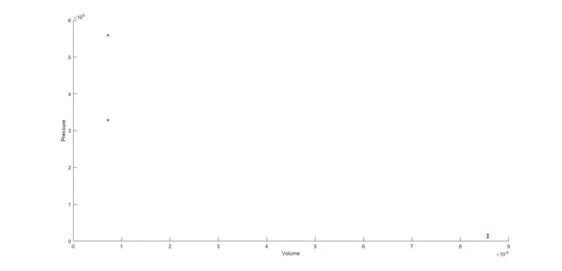
The next step is to join these points, but the problem is by using the plot command the results we get might be straight lines. This is not the correct method to show the volume change inside the combustion chamber. That's why we use the function code to get the volume change which we get the correct output by including the geometric parameters.
Function Code:
%Calculating the Piston Kinematics to find the change in volume inside the combustion chamber

function [V] = engine_kinematics(bore, stroke, con_rod, cr, start_crank, end_crank)

a = stroke/2;
R = con_rod/a;

v_s = pi/4*bore^2*stroke;
v_c = v_s/(cr-1);

theta = linspace(start_crank,end_crank,100);

term1 = 0.5*(cr-1);
term2 = R +1 - cosd(theta);
term3 = (R^2 - sind(theta).^2).^0.5;


V = (1 + term1*(term2 - term3)).*v_c;

end
For solving the piston kinematics we have to consider the crank angles from start to end. That's why we use linspace command for generating the array. The change in volume inside the combustion chamber is calculated by using the equation based on the engine parameters.
OUTPUT:
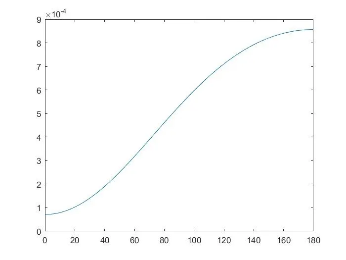
The above figure shows the change in volume. It doesn't change linearly but in the curved profile.
Final Code:
In the final code, we have to merge the two codes mentioned above by calling the function instead of including the entire code.
clear all
close all
clc

%Inputs
gamma = 1.4
t3 = 2300

%State variables
p1 = 101325
t1 = 500

%Engine geometric parameters
bore = 0.1;
stroke = 0.1;
con_rod = 0.15;
cr = 12;

%Calculating the swept volume and the clearance volume
v_swept = (pi/4)*bore^2*stroke;
v_clearance = v_swept/(cr-1);

v1 = v_swept + v_clearance
v2 = v_clearance

%State variables at state point 2
%p2v2^gamma = p1v1^gamma
%p2 = p1*(v1/v2)^gamma = p1*cr^gamma
p2 = p1*cr^gamma

%p1v1/t1 = p2v2/t2 | t2 = p2*v2*t1/(p1*v1)
t2 = p2*v2*t1/(p1*v1);

%For an isentropic process
constant_c = p1*v1^gamma;
V_compression = engine_kinematics(bore, stroke, con_rod,cr,180,0);
P_compression = constant_c./V_compression.^gamma

%State variables at state point 3
v3 = v2

%p3v3/t3 = p2v2/t2 | p3 = p2*t3/t2
p3 = p2*t3/t2


%For an isentropic process
constant_c = p3*v3^gamma;
V_expansion = engine_kinematics(bore, stroke, con_rod,cr,0,180);
P_expansion = constant_c./V_expansion.^gamma


%State variables at state point 4
v4 = v1

%p3v3^gamma = p4v4^gamma | p4 = p3(v3/v4)^gamma
p4 = p3*(v3/v4)^gamma

%Thermal efficiency of the engine|Efficiency = 1-(1/cr^(gamma-1))*100

Efficiency = (1-(1/cr^(gamma-1)))*100


figure(1)
hold on
plot(v1,p1,'*','color','r')
plot(V_compression, P_compression)
plot(v2,p2,'*','color','r')
plot(v3,p3,'*','color','r')
plot(V_expansion, P_expansion)
plot(v4,p4,'*','color','r')
plot([v2 v3],[p2 p3],[v1 v4],[p1 p4],'color','g');
xlabel('Volume')
ylabel('Pressure')
- After calculating the state variables at state point 2, we have to calculate the compression volume and compression pressure after the compression happens.
- [V] is an array used to plot the curve required to join the points 1 and 2.
- v_compression is calculated by using the function code.
- p_compression is calculated by using the relationship p1v1^gamma = constant as it is an isentropic process.
- Similarly after calculating the state variables at state points 3 and 4. By using the same procedure for compression, we have to calculate the expansion volume and expansion pressure after the expansion happens.
- Efficiency is calculated by using the formula based on the compression ratio that we used.
By using the plot commands we will plot all the values to get the desired output.
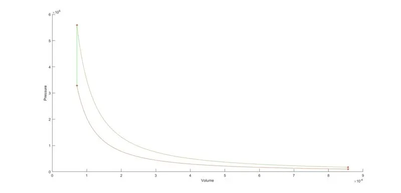
Final Output:
Efficiency of the Engine:
Here I've attached the output for the efficiency of the engine calculated.
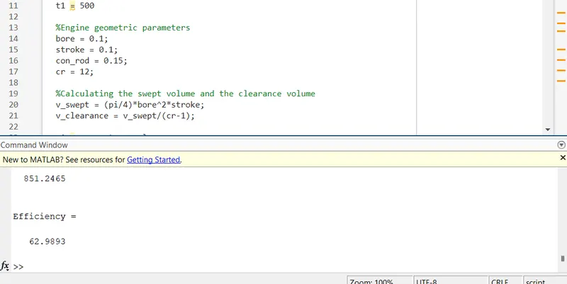
The efficiency actually we got is based on the parameters that we provided. The efficiency has been improved by making some changes in the engine parameters.
Errors facing while writing the code :
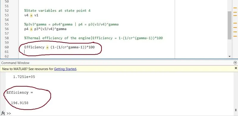
I made a mistake while writing the formula for efficiency. This can be identified by getting the efficiency value which is nearly 200.
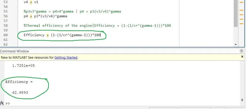
By including the open bracket '(' and closed bracket ')' in the right place for the efficiency formula, the error is corrected as shown in the image below
Conclusion:
From the final output, the code written is suitable for creating the plot for an Otto Cycle and also to calculate the efficiency of the engine. Here, the efficiency that we got is to be 62.98%. The efficiency can be improved by making some changes in the engine parameters.