Ahmed Body Challenge
Flow over Ahmed's Body :
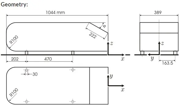
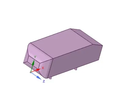
The Ahmed body is a geometric shape first proposed by Ahmed and Ramm in 1984. The shape provides a model to study geometric effects on the wakes of ground vehicles (like cars).The Ahmed body represents a simplified, ground vehicle geometry of a bluff body type. Its shape is simple enough to allow for accurate flow simulation but retains some important practical features relevant to automobile bodies. This model describes how to calculate the turbulent flow field around a simple car-like geometry.
With the experimental data available many testing and simulation tools can be examined for their accuracy.
Negative pressure in the wake region:
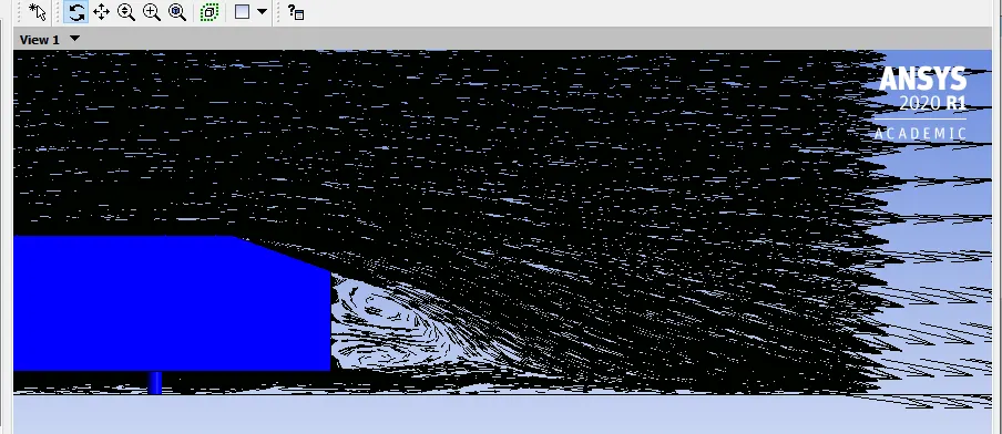
Negative pressure in the wake region is due to flow detachement from the surface of body, leading to formation of vortices which detach periodically and flow separation resulting in flow of air in the opposite direction which is due to viscosity effects, well explained using boundary layer concept. This flow separation can be minimized by low slant angles (w.r.t horizontal) and also by using vortex generators in case of aero Foil.
This negative pressure leads to pressure differences and in turn increases drag force on vehicles.
Significance of point of separation:
This point of separation on the vehicles (ahmed’s body in our case) decides the size of wake region and pressure drag, if wake region is large and pressure difference is high then drag force on the vehicle is high resulting in less performance (less speed) on the other hand if the wake region is small, less pressure drag on increased performance of the vehicle.
This point of separation is mainly influenced by slant angle `phi<=30^0` then an inward rotating pair of vortices with increasing strength is observed at back side of vehicles [4]. Therefore, the Ahmed body with the rear slant angle of 25° belongs to the back side of vehicles, which exhibit very strong inward longitudinal vortices at the rear side. These vortices extend far into the wake region and generate a field of downwind in the enclosed region. At a slant angle of 30°, i.e., directly before transition to the full square back flow, this pair of vortices is developed most strongly, and the flow separates at the lower edge of the slant. This produces strong under pressures at that position, so that the aerodynamic drag reaches its maximum in this state.
Default mesh setup :
Space claim model:
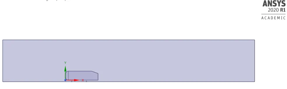
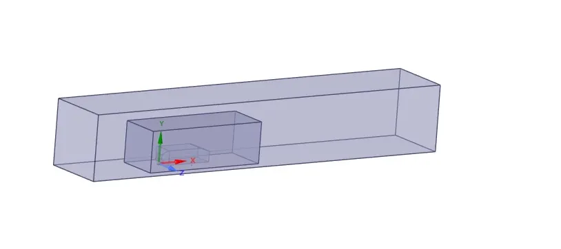
As it is an external flow enclosure in used .
Interference check has been done and the region has been corrected so that mesh doesn't overlapp.
Mesh model: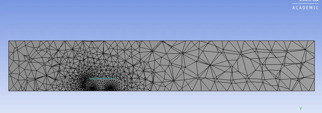
Element size: 413.6 mm
Number of Elements: 83781;
Mesh type: Quad dominant .
Solving:
Named selections: Inlet, outlet, symmetry , car wall.
Boundary conditions:
velocit inlet, pressure outlet, symmetry.
Hybrid initialization
Turbulance model: k-epsilon , standard.
Reference values: Area- 0.31482 (x-direction);
Length-1.062;
rho=1.225 kg/m^3;
velocity-25 m/s;
Viscosity-1.789e-05;
solution:
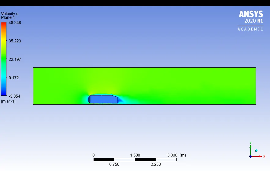
Velocity contour:
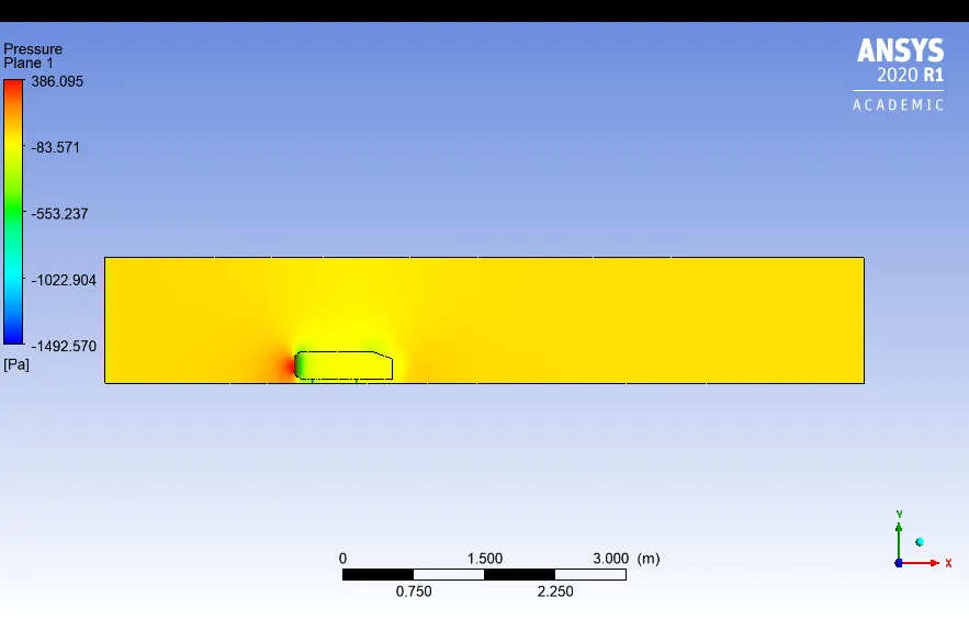
pressure contour:
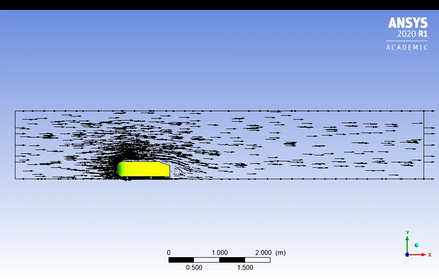
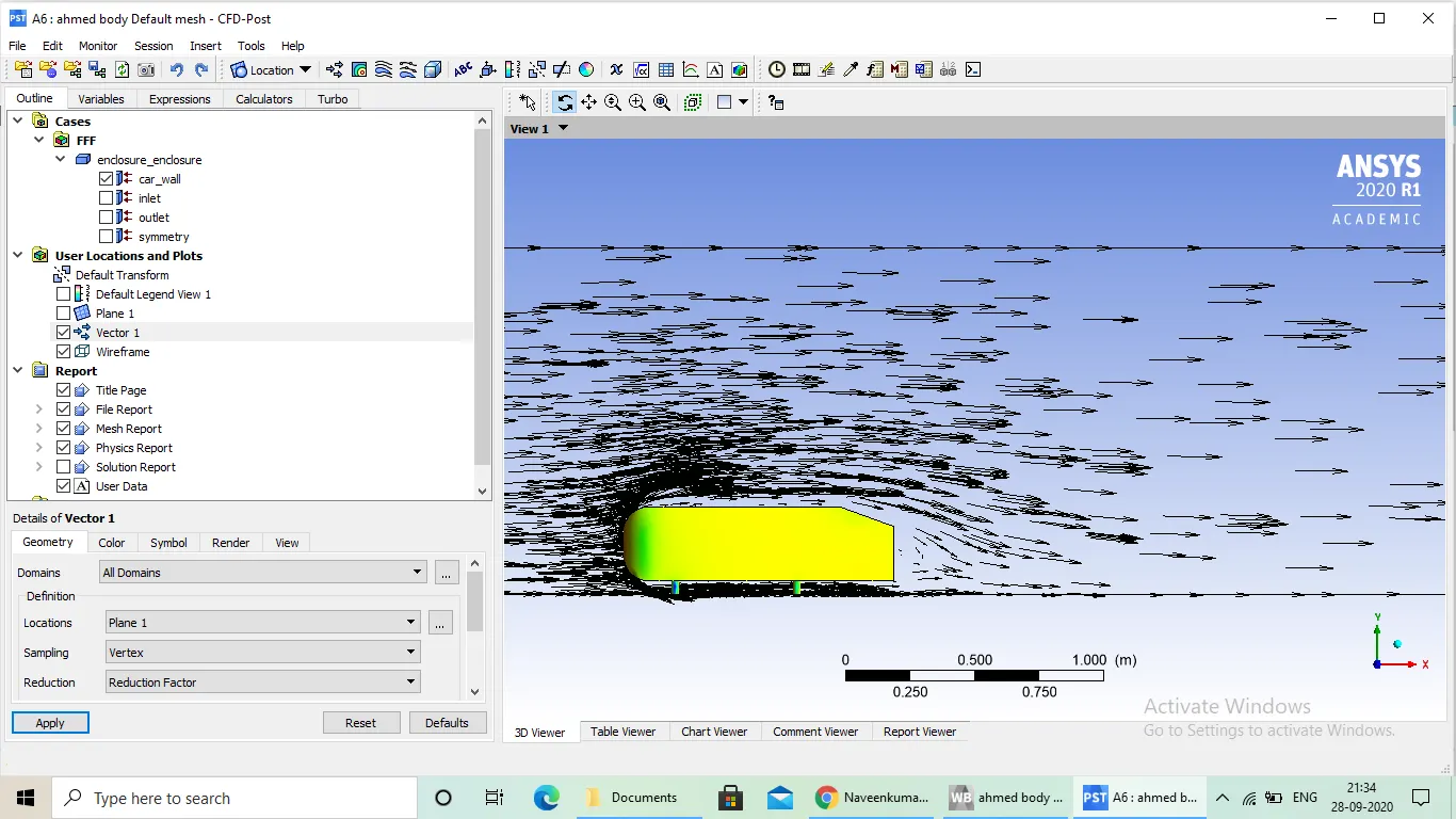
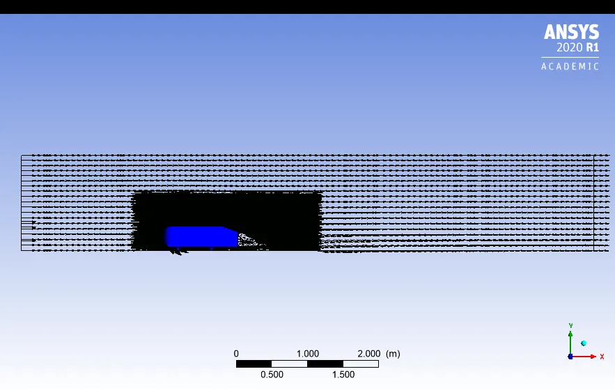
vector plot:
Refined mesh 1:
Modified enclosure:
mesh :
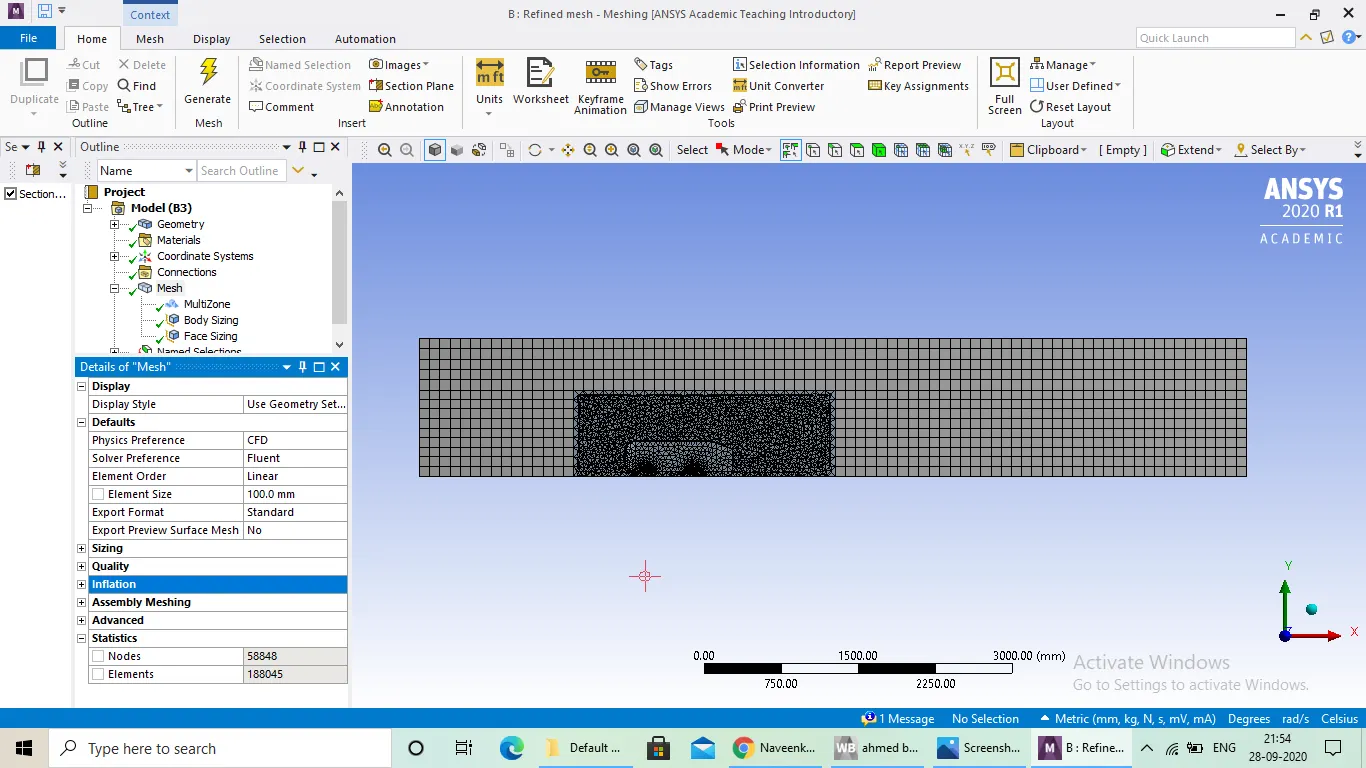
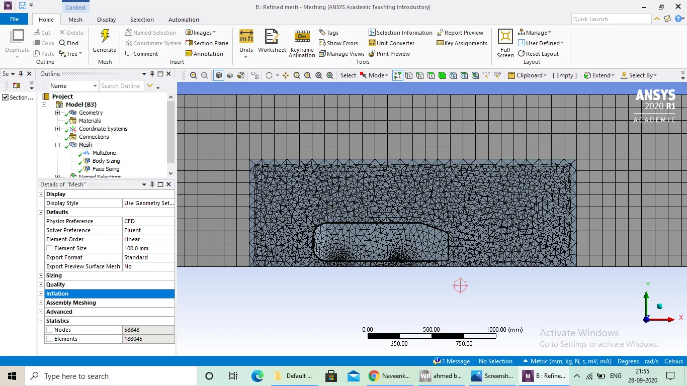
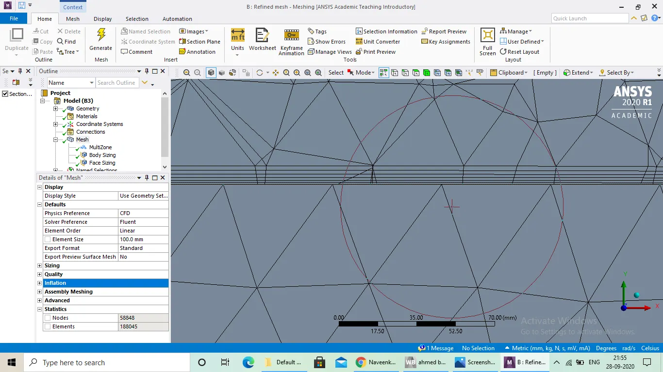
Multizone has been introduced in to the model, outer zone mesh is of hexahedral type and inner core and finer mesh size is of quad dominant and ahmed's body (outer )is of traingular mesh.
Element size: outer box -100mm;
Refinement region-50mm;
No.0f elements: 188045;
Inflaion layers are also added to capture the flow just over the surface.
No.of layers: 6;
growth rate : 1.2;
Total thickness: 8.957;
Results:
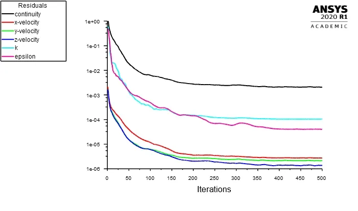
Residuals: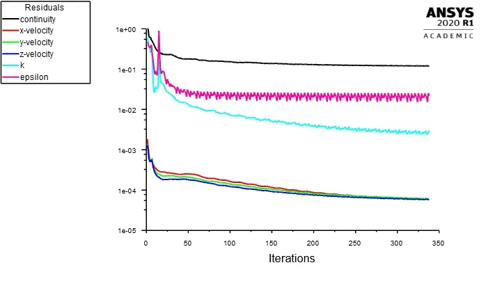
Veocity contour: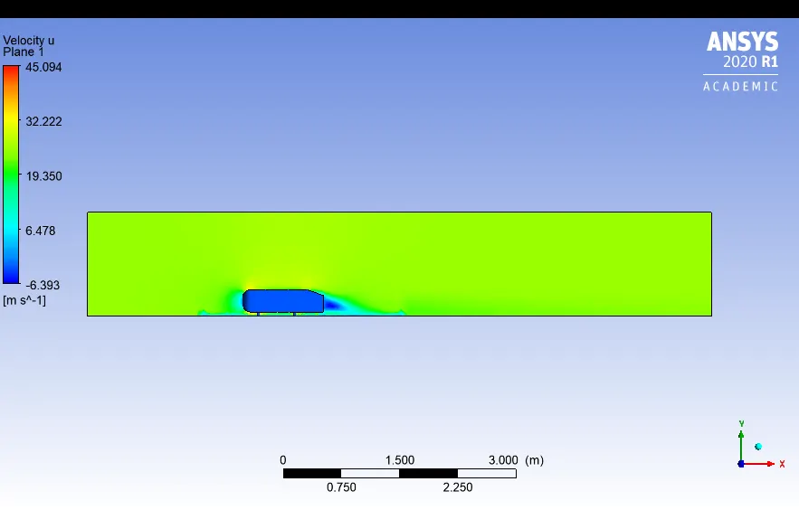
pressure contour: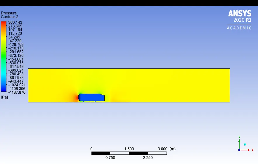
vector plot:
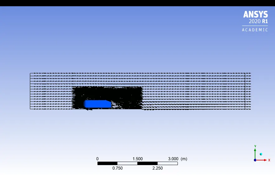
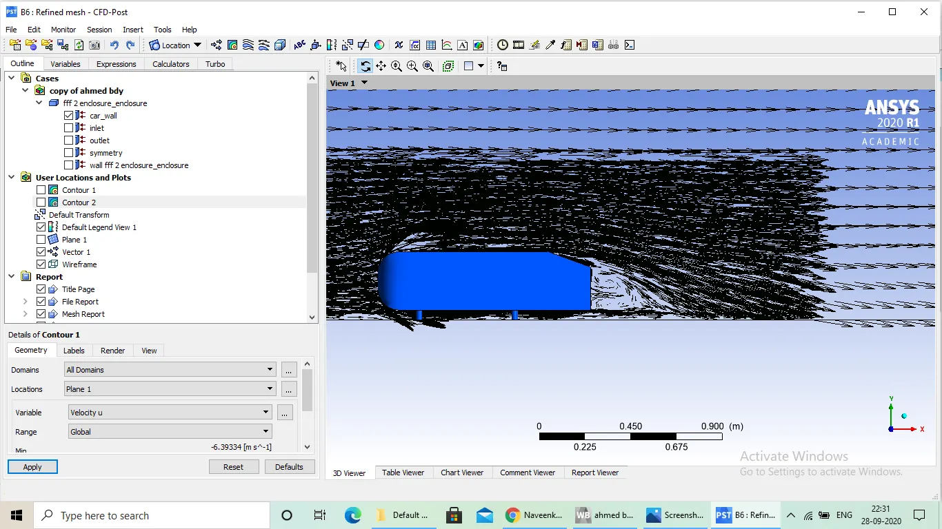
Refinement 2:
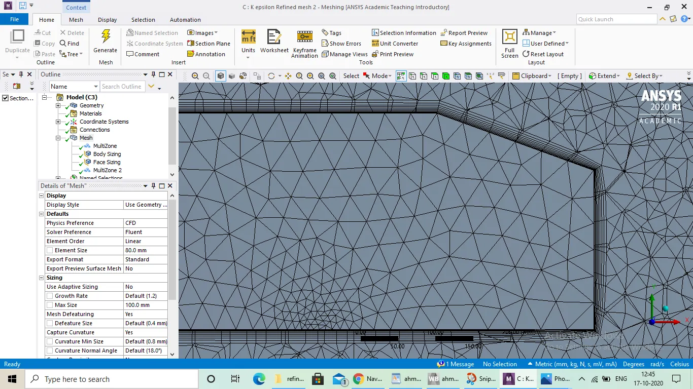
mesh :
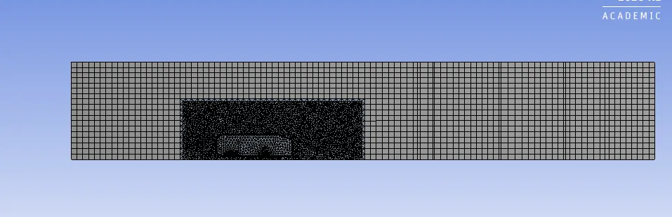
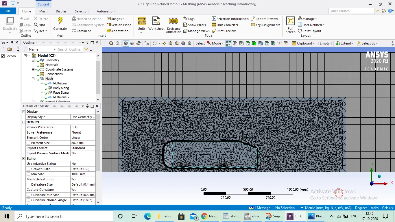
Multizone has been introduced in to the model, outer zone mesh is of hexahedral type and inner core and finer mesh size is of quad dominant and ahmed's body (outer )is of traingular mesh.
Element size: outer box -80mm;
Refinement region-35mm;
No.0f elements: 428689;
Inflaion layers are also added to capture the flow just over the surface.
No.of layers: 10;
growth rate : 1.2;
Total thickness: 18.575;
Results:
Residuals: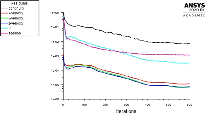
Veocity contour:
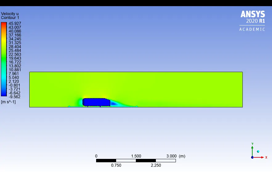
Veocity contour:
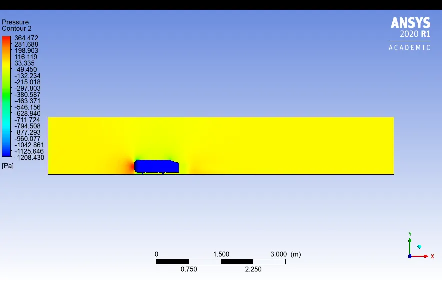
Vector plot:
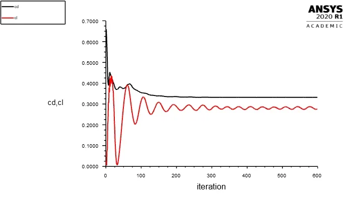
Drag and lift plot:
Grid independency test:
Three mesh sizes have been used for performing grid independency test in all the zones:
1) mesh size- 413.6mm (default);
2)mesh size-100 mm;(outer box) , refinement zone- 50mm;
3)mesh size-80 mm ;(outer box), refinement one -35mm;
| mesh size9(mm) | No.of elements | Cd(given reference value=0.33) | Cl | percentage error of drag value w.r.t standard vaue given |
| 413.6 | 83781 | 0.372 | 0.217 | 12% |
| 100 | 188045 | 0.3645 | 0.225 | 9% |
| 80 | 428689 | 0.332 | 0.2766 | 0.2% |
Conclusion:
1)From the above Table ,we can conclude that for three different mesh sizes ranging from basic to refined case the result obtained in terms of coefficient of drag and lift were not much appreciable at the cost of increased computational time, computational power , increasd memory usage hence it can be concluded that our model is grid independent up to one decimal point.
2)K-epsilon ,standard model is used for all the three cases given good results when compared with given reference value.
3)As discussed earlier, Point of seperation plays very important role in overall performance of vehicle as it is major factor which is responsible for pressure drag ,optimal slant angle resuting in the smoth flow of air over the surface and no detachment of flow from then surface of body.