Advanced Sheet Metal Design Using NX Cad Challenge_7_ Metal bracket-II
TITLE : Sheet Metal Bracket II Design using Siemens NX
OBJECTIVE:
To learn the Sheet Metal design process and to design a Sheet Metal bracket II in parametric CAD software Siemens NX following industrial workflow.
INTRODUCTION:
Sheet Metal is a metal with a small thickness ranging from 0.5-6mm which is made thin and flat by rolling or hammering process. A number of mechanical components are made up of Sheet Metal. Sheet metal is widely used in the manufacturing industry for making numerous daily used products due to its various advantages.
In Sheet Metal, a constant called K factor rules the bend parameters of all the bends in the part. It is the ratio of the length of the neutral axis to the thickness of the sheet metal.
In this project, a bracket is designed in Siemens NX CAD software following the industrial approach. The use of a parametric modelling environment is the main use made in this project. This project focuses on the stiffening process of a bracket with the application of advanced flanges. All the sheet metal design considerations are carefully considered while doing this project.
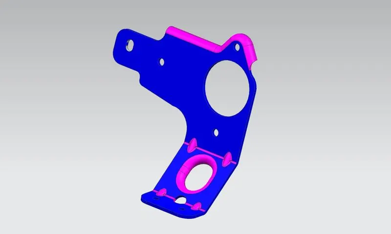
DESIGN METHODOLOGY:
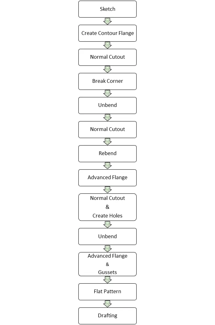
The bracket designed for this project consists of features like contour flange, normal cut-outs, advanced flanges, and holes. Every feature is designed in an order following the industrial procedure to keep the design intent. The design methodology used for this project can be summarized as depicted in the flowchart below
DESCRIPTION:
- Sketch in the YZ Plane.
In order to create a couple of normal cut-outs in the bracket, the sketch is initially created keeping the profile accurately.
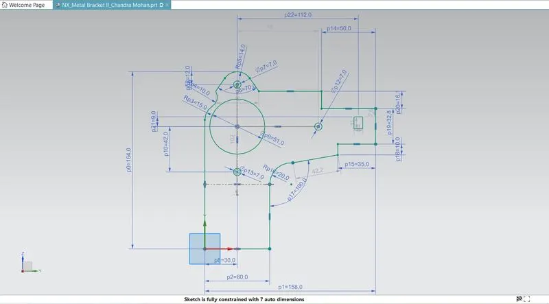
Sketch for contour flange:(XZ Plane)
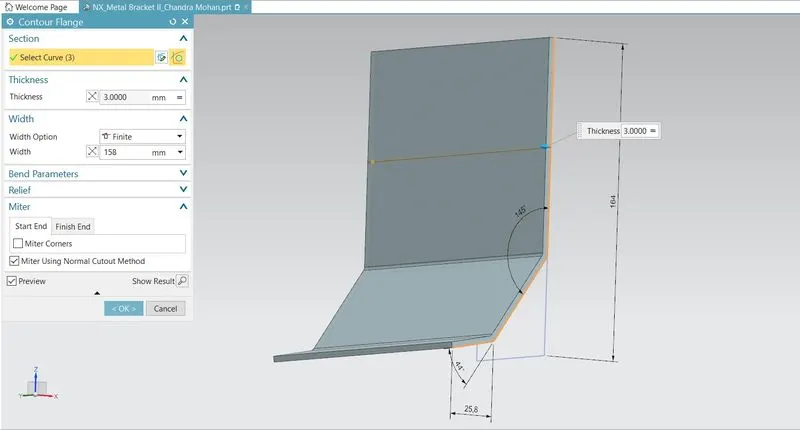
A contour flange can be created from any open curve. For this bracket, the sketch is created in an XZ plane with the following dimensions.
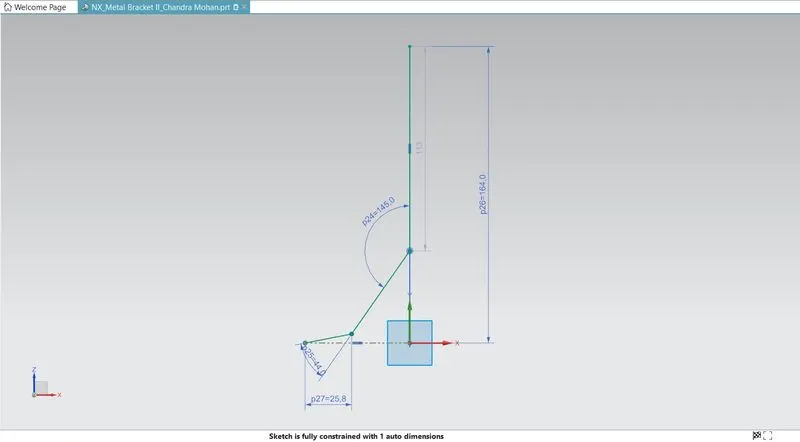
Contour Flange:
The contour flange is a flange created using the open sketch created in a plane. It is different from regular flange because it can be created in any shape and it does not require choosing the edge of any tab or existing flange. It can be at any position or at any angle. For this bracket design, a contour flange is created using the earlier sketch as the curve.
Normal Cut-out:
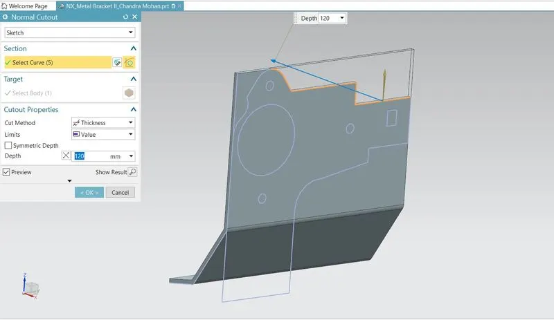
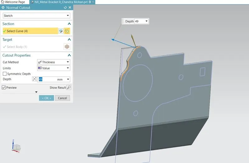
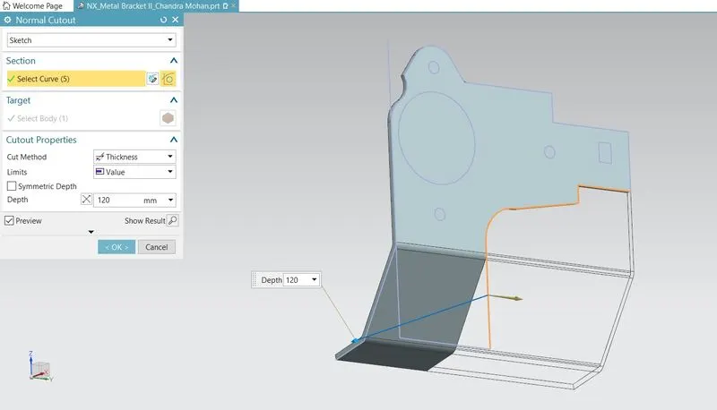
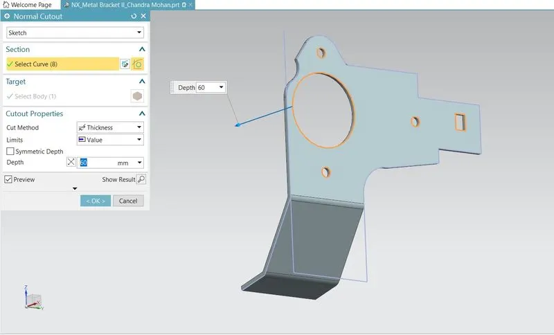
It cuts away the material at the right angle with respect to the sketch plane. A closed sketch is created on the YZ plane to cut away the unnecessary material. Sketch 1 is projected and the required closed contours are sketched wherever cuts required. Then the operation normal cut out is carried out.
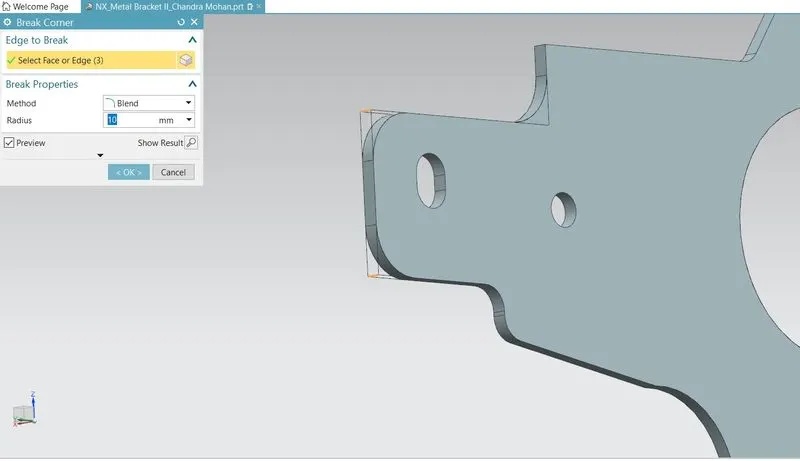
Break Corner:
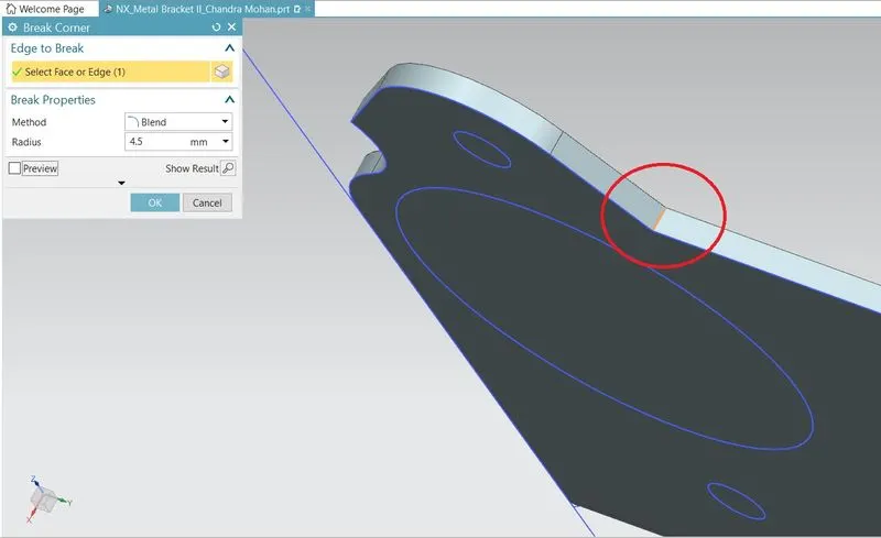
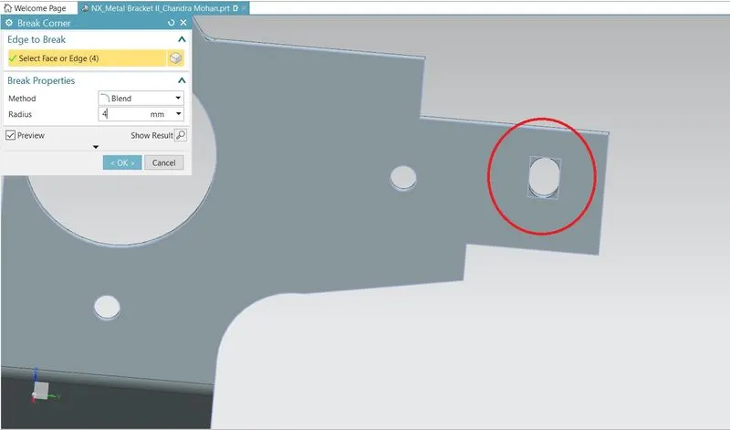
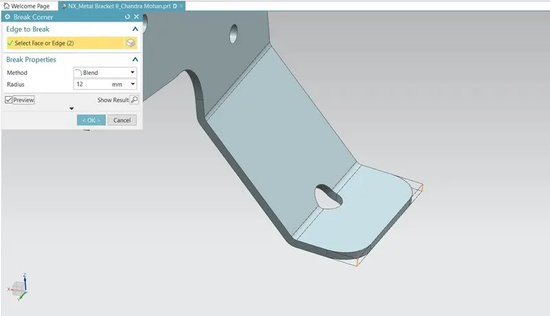
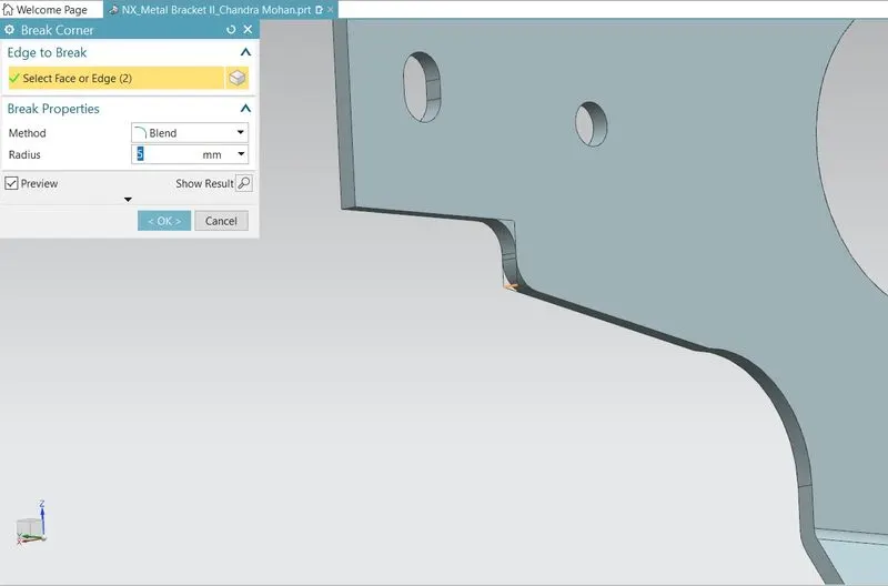
Break Corner rounds off the sharp corners in the sheet metal part. It is just like a fillet feature in other CAD software. It replaces the sharp end with round edges or faces making it smooth and reducing the chances of failure and stress concentrations at the sharp ends. In this bracket, break corner is used in several corners with an appropriate radius as shown below.
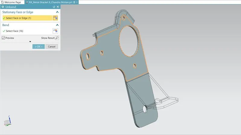
Unbend:
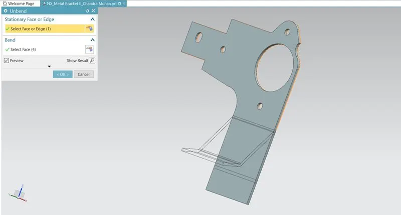
This is a very powerful and very useful tool in Siemens NX. It allows all the bends made by the various features to the unbent state at once. In order to achieve a flat configuration of the sheet metal as per the design intent, it is necessary to choose the bends in order. It is also possible to box select all the bends at once. Once the unbend feature is used, further features can be carried out using the sketches created in the unbent state.
Normal Cut-out:
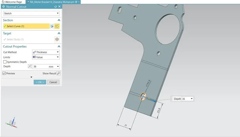
It cuts away the material at the right angle with respect to the sketch plane. A circle is created on the YZ plane in an unbent state. One of the important things to note in this step is that any hole or notch like opening should be at least three times the thickness+ bend radius away from the bend.
Rebend:
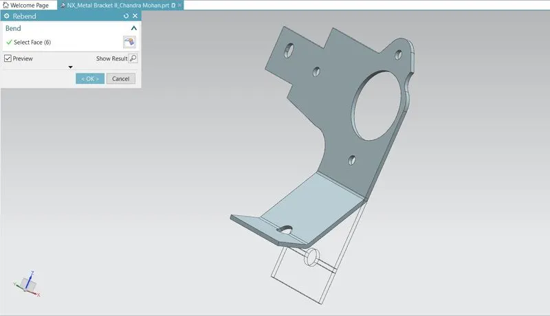
All the features added after the unbend feature are added in the unbend state itself. After the addition of sketches and additional features are completed, the sheet metal component has to be rebent to the required position. This is done using the rebend feature and selecting all the bends in order or by box selection.
Break Corner:
Again, the break corner is used in several corners with an appropriate radius as shown below.
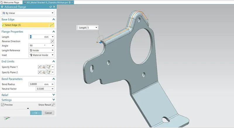
Advanced Flange:
Unlike base simple base flange, the advanced flange can create flange from any edge which can be either curved or straight line, open or closed profile. This allows creating a flange with a match face also. For this bracket, the advanced flange is created at the upper portion with proper parameters as shown.
Unbend:
Again the unbend feature is applied after which a couple of features are applied.
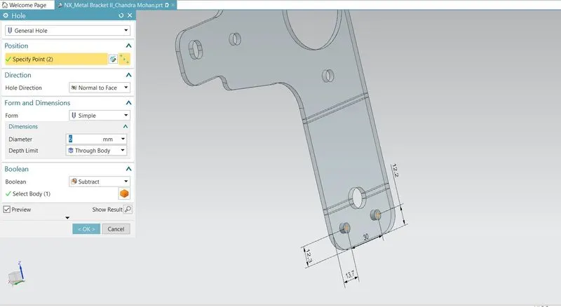
Hole:
The hole feature in sheet metal is similar in solid modelling. Here, two general holes of 6 mm radius are created while in the unbent state.
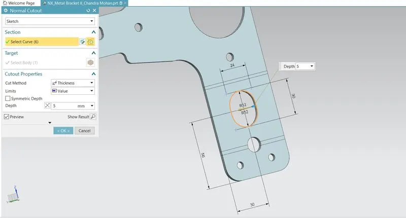
Normal Cut-out:
Again, a couple of normal cut-outs are carried out in the unbent state as shown below.
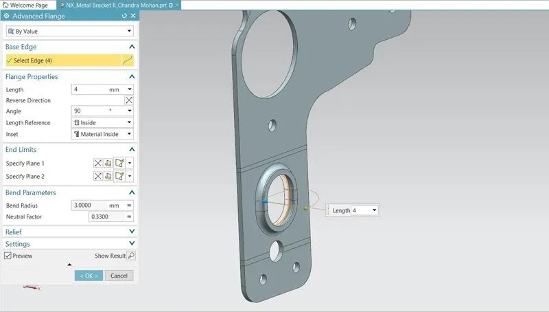
Advanced Flange:
Again, an advanced flange is applied at the edge of the normal cut-out created in the above step.
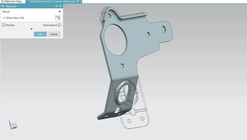
Rebend:
All the features added after the unbend feature are added in the unbend state itself. After the addition of sketches and additional features are completed, the sheet metal component has to be rebent to the required position. This is done using the rebend feature and selecting all the bends in order or by box selection.
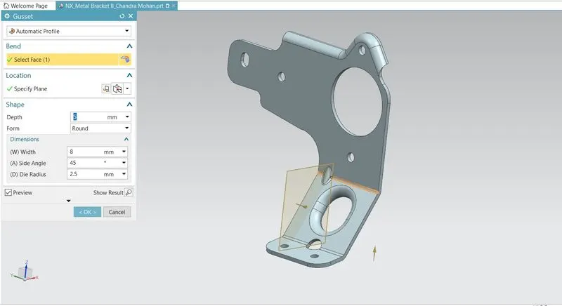
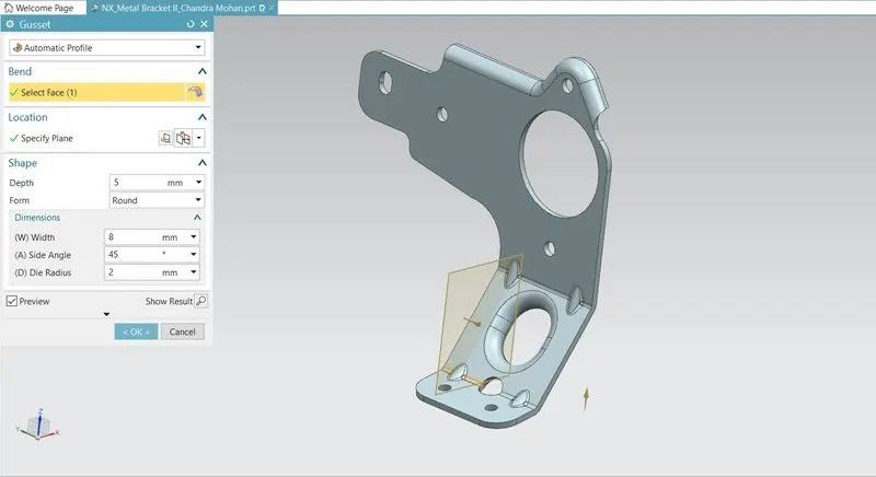
Gussets:
Gussets are basically supporting features that provide the structure of the part of the product form the base tab or flange wherever the bend exists. These are stiffening features applied at the bends. For this bracket, four rounded gussets are applied in the bends as shown below.
Flat Pattern:
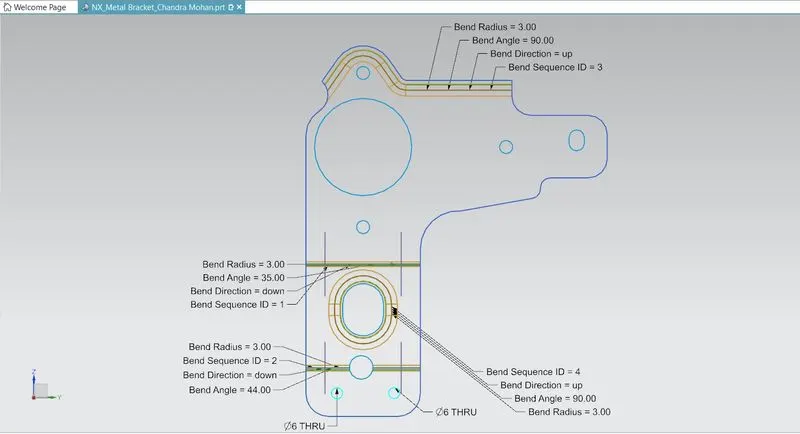
Flat pattern is the representation of the entire sheet metal component in the 2D form of the flat sheet metal with all the bends, cut-outs, holes, and additional features in the form of lines or edges. The flat pattern ensures the ability to cut the sheet metal out of the raw sheet metal plate. It removes the possible errors such as interference or collision within the same component.
DRAFTING(Drawing Sheet)
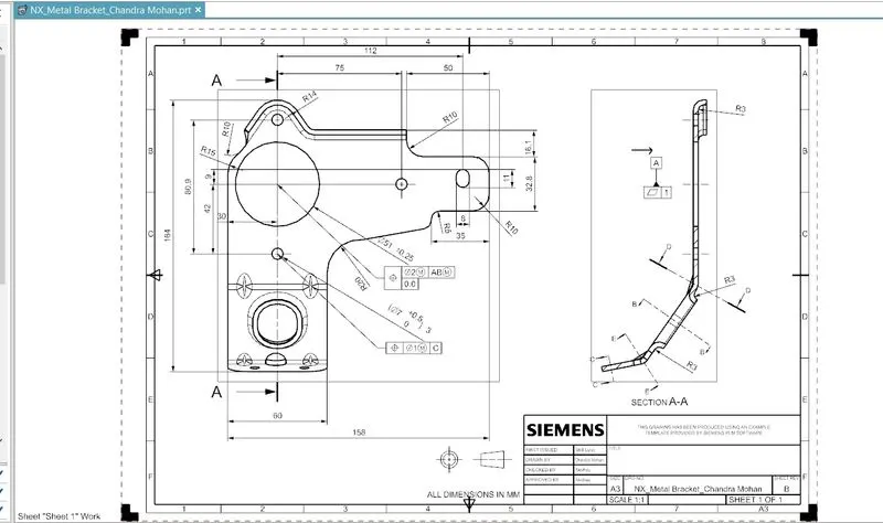
After the design is complete, the execution or the manufacturing of the component requires a technical drawing of the component with the provided scale and with accuracy. The necessary details such as annotations, callouts, bend tables can be added as per the requirement. For this bracket design project, a drawing is created out of the flat pattern in a 1:1 scale in an A3 sheet, and an additional drawing showing different views is also shown.
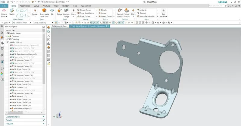
Model with Feature Tree:
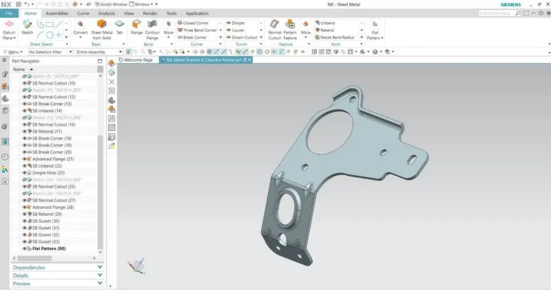
Design of Metal Bracket II
(MODEL VIEWS)
Front View:
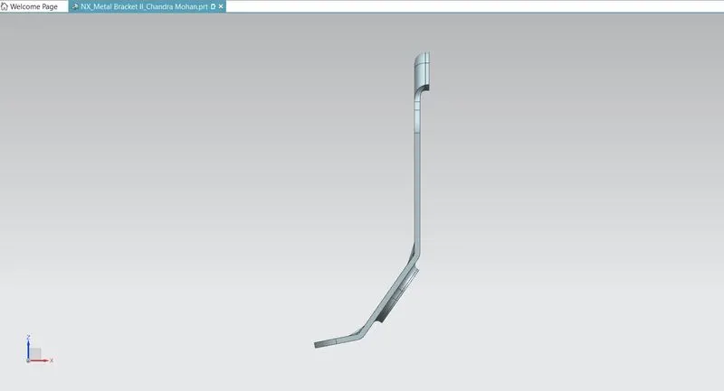
Top View:
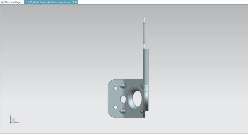
Bottom View:
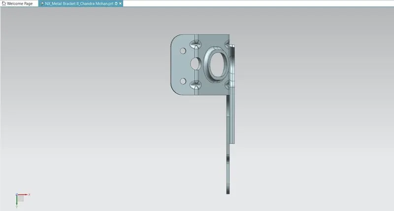
Right Side View:
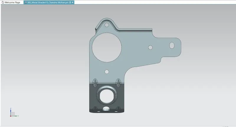
Left Side View:
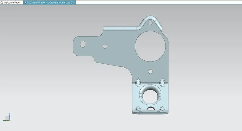
Isometric View:
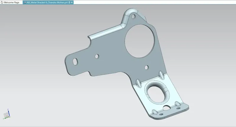
Wireframe View:
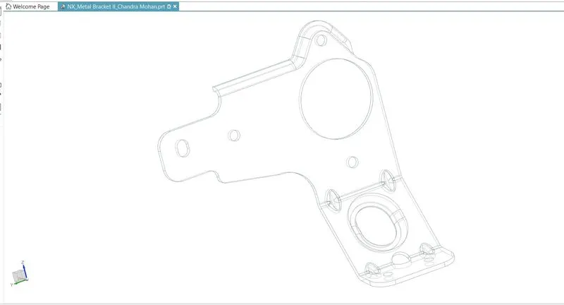
CONCLUSION:
In this project, a Sheet Metal bracket is successfully designed from a solid body in the sheet metal workbench of Siemens NX. The advantage of a parametric modelling environment is used to maintain our desired design intent and all the necessary features are applied in order following the industrial workflow.